1332/1432 QUICK REFERENCE - Woodcraft
1332/1432 QUICK REFERENCE - Woodcraft
1332/1432 QUICK REFERENCE - Woodcraft
- No tags were found...

You also want an ePaper? Increase the reach of your titles
YUMPU automatically turns print PDFs into web optimized ePapers that Google loves.
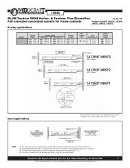
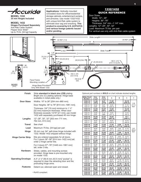
MODEL <strong>1332</strong>35 mm Hinges IncludedMODEL <strong>1432</strong>Hinges Purchased SeparatelyAnti-Rak Cable SystemFlipper Door Slide ®Up to 75 lb. [34 kg] CapacityApplications: Vertically mountedconcealed doors for office/residentialstorage cabinets, entertainment centers,and armoires. Use model <strong>1332</strong>/<strong>1432</strong>with unique Anti-Rak cable system toeliminate door sag and wracking. Thisproduct is covered by U.S. (4,974,912)and various foreign patents issuedand/or pending.<strong>1332</strong>/<strong>1432</strong><strong>QUICK</strong> <strong>REFERENCE</strong>Door Sizes:Width: 10"– 26"Heights: 36"–78"Thickness: 3/4" min.–1 1/4" max.Lengths: 12"–28", 30", 32"Load: Maximum 75 lbs. per pairFor vertical use only with Anti-Rak cable system1Slide Length.04 REF. [1.0] .09 REF. [2.3]A.88[22.3].75 [19.1](2X)1.29[32.8]1.00[25.4]D REF..38 (2X) [9.5]BC.38 [9.5] DIA..25 (5X) [6.4]Slide Travel.180 X .210[4.6 X 5.3] (2X).69[17.6]1.26[32.0].180 X .374[4.6 X 9.5]INCHES[mm]Face FrameMounting LocationHinge Base ProvidedOnly With Model <strong>1332</strong>.180 [4.6]DIA.FinishDoor SizesLengthsTravelLoadHingeHinge Carrier StripHardwareOperating EnvelopeFeaturesSlide standard in black zinc (CB) plating.Bright zinc (C) plating optional. Hinge baseavailable in nickel plate only.•Widths: 10" to 26" [254 mm–660 mm].Door Heights: 36" to 78" [914 mm–1981 mm].Thickness: 3/4" [19 mm] minimum to 1 ¼"[32 mm] maximum thickness. When doorthickness exceeds 13/16" [21 mm], use model<strong>1432</strong> with separately purchased 40 mm hinge.12"–28", 30", 32" [303 mm–711 mm,762 mm, 813 mm]See chartMaximum 75 lbs. [34 kgs] per pair35 mm cup; 94° self-close hinge included with<strong>1332</strong>. Model <strong>1432</strong> shipped without hinge.Kits are ordered separately for all doors.For 2 doors 36"–56" [914 mm–1422 mm] tall,order 2 hinge carrier kits.For 2 doors 57"–78" [1448 mm–1981 mm]tall, order 3 kits.Slides, cables, and mounting screwsprovided. Hinge base is pre-mounted onlyon model <strong>1332</strong>.A 2"–2 ½" [50.8 mm–63.5 mm] “pocket” isrequired to clear the retracting door and theprotruding hinge arms.Detent out, silenced open and closed.• RoHS compliant.Optional part numbers in BOLD on chart indicate stocked lengths.Slide PartNumber<strong>1332</strong>-12<strong>1432</strong>-12<strong>1332</strong>-13<strong>1432</strong>-13<strong>1332</strong>-14<strong>1432</strong>-14<strong>1332</strong>-15<strong>1432</strong>-15<strong>1332</strong>-16<strong>1432</strong>-16<strong>1332</strong>-17<strong>1432</strong>-17<strong>1332</strong>-18<strong>1432</strong>-18<strong>1332</strong>-19<strong>1432</strong>-19<strong>1332</strong>-20<strong>1432</strong>-20<strong>1332</strong>-21<strong>1432</strong>-21<strong>1332</strong>-22<strong>1432</strong>-22<strong>1332</strong>-23<strong>1432</strong>-23<strong>1332</strong>-24<strong>1432</strong>-24<strong>1332</strong>-25<strong>1432</strong>-25<strong>1332</strong>-26<strong>1432</strong>-26<strong>1332</strong>-27<strong>1432</strong>-27<strong>1332</strong>-28<strong>1432</strong>-28<strong>1332</strong>-30<strong>1432</strong>-30<strong>1332</strong>-32<strong>1432</strong>-32SlideLength11.94[303]12.94[329]13.94[354]14.94[379]15.94[405]16.94[430]17.94[456]18.94[481]19.94[506]20.94[532]21.94[557]22.94[583]23.94[608]24.94[633]25.94[659]26.94[684]27.94[710]29.94[760]31.94[611]SlideTravel8.27[210]9.27[235]10.27[261]11.27[286]12.27[312]13.27[337]13.52[343]14.52[369]15.52[394]16.52[419]17.52[445]18.52[470]19.52[496]20.52[521]21.52[546]22.52[572]23.52[597]25.52[648]27.52[699]A B C D11.81[299.9]12.81[325.3]13.81[350.7]14.81[371.1]15.81[401.5]16.81[426.9]17.81[452.3]18.81[477.7]19.81[503.1]20.81[528.5]21.81[553.9]22.81[579.3]23.81[604.7]24.81[630.1]25.81[655.5]26.81[680.9]27.81[706.3]29.81[757.2]31.81[807.9]6.99[177.5]7.49[190.2]7.99[202.9]8.49[215.6]8.99[228.3]9.49[241.0]9.99[253.7]10.49[266.4]10.99[279.1]11.49[291.8]11.99[304.5]12.99[329.9]13.99[355.3]10.10[256.5] 3.0611.10[281.9]12.10[307.3]13.10332.7]14.1[358.1]15.10[383.5]16.10[408.9]17.10[434.3]18.10[459.7]19.10[485.1]20.10[510.5]21.10[535.9]22.10[561.3]23.10[586.7]24.10[612.1]25.10[637.5]26.10[662.9]28.10[713.7]30.10[764.5][77.7]REF.3.81[96.8]REF.
Installation Instructions 35. Tighten fixing screw and release slide plate.CAUTION: Do not cut excess cable yet!6. In a similar manner, uncoil cable at lower slide and route it alongthe slide and around front side of pulley groove. See Figure 3.Figure 2AHold cableand pushplate back.7. Extend to back side of upper slide pulley. Pass cable aroundpulley groove and forward. Move upper slide plate to its mostrearward position.8. Wrap cable around upper adjuster block. With very light tensionwrap cable around upper fixing screw. Tighten fixing screw.Ensure cable exits screw head near wall. See Figure 3.9. Bring both slide plates fully forward and engage detents. Adjustcable enough to remove excess slack only.NOTE: Too much tension in cables will cause poor movement.Ensure both cables are in pulley groove after threading.STEP 3Assemble Hinge Carrier StripFigure 3To determine the number of individual hinge carrier stripsrequired, refer to the chart on Page 2. Attach connector clipusing #8 screws. See Figure 4.1. Align the two carrier strips so the Accuride logo is at the top.Flip the top one over, so the logos face each other. Extend thestrips and attach to slide plates. See Figure 4.2. Install two #8 hinge carrier screws D on the top and bottom ofthe assembly (only partially tightening the screws).3. Snap connector clip G into position (to hold strips together), andalign the assembly to the slide plates. (Check fit.)4. Position the hinge carrier strip assembly behind the slide plate,and insert the partially installed mounting screws through thekeyhole slots.5. Expand the assembly into position and fully tighten the screwsto secure hinge carrier strip to the inner member D .PulleySlide PlatePackaging (Hold fullyrearward)CableFixingScrewCableAdjustorBlockCableTensionScrew6. Position the connector clip (or clips) to the desired location andfasten with the remaining #8 screws D without hinge base or Ewith hinge base.Pulley7. The connector clip is also used for mounting additional hingebase plates on larger applications using screw E .Figure 4Hinge carrier stripsare unhandedand infinitelyadjustableOverlap6" Min.ConnectorClip GAttach using *#8 ScrewsD or EFigure 3AHingeCarrierStripLogo(Facing Up)Logo On Backside(Facing Down)IncorrectInstallationCorrectInstallation* If holes are not aligned, switch positions of strips. Pre-installscrews in end holes for insertion into keyhole slots on slide plate.Connector screws may have to be removed when installing.
Installation Instructions 4STEP 4Install Hinge BasesFor model <strong>1332</strong>: Hinge base already attached to slide in flush insetposition (rearmost holes). See Figure 5.For model <strong>1432</strong>: Select hinge brand and model. Install as shown inFigure 5 for flush inset applications.• See Page 6 for hinge manufacturers and part numbers byapplications.Mounting with spacers (for hinges other than Salice).STEP 5Place spacer(s) between the hinge base and slide plate. Securewith #8 x 5/8" hinge base screws (not provided).Bore Hinge Cup-35 mm-Model <strong>1332</strong>NOTE: ALWAYS bore a rough simulated door first to verifyhinge cup locations.See Figure 6 for hinge cup hole location. Bore top and bottom 35 mmholes 1/2" [12.7 mm] deep on the inside of door back. Dimensions arebased on mounting slides flush with the floor and ceiling.Inset Doors3/4"–13/16" [19.0 mm–20.6 mm]35 mm Salice Hinge(C2P7A33 with 3mm Base)Door Thickness Tab Door Gap Door Clearance3/4"[19.0 mm]13/16"[20.6 mm]5/16"[8.0 mm]11/32"[9.0 mm] ‡3/32" *[2.3 mm]1/16" •[1.8 mm]1/16"[1.4 mm]1/64"[0.3 mm]* For smaller door gap, increase tab. Notching may be required.‡ May require notching.• Will require hinge lateral adjustment to achieve door gap.Bore Hinge Cup-40 mm-Model <strong>1432</strong>Inset Thick Doors13/16"–1 ¼" [20.6 mm–31.8 mm]40 mm Salice Hinge(CFA7G99 with 3 mm Base)Maximum Door Thickness Tab Door Gap Door Clearance1 ¼"[31.8 mm]19/32"[15.0 mm]3/32"[2.3 mm]Overlay Doors3/4" [19.0 mm] Thick40 mm Salice Hinge(CFA7A99 with 0 mm Base)1/16"[1.6 mm]Maximum Door Thickness Tab Overlay Door Clearance3/4"[19.0 mm]19/32"[15.0 mm]7/16"[11.7 mm] ++ To improve door clearance, adjust hinge to increase reveal.1/64"[0.4 mm] +Pocket WidthThe chart below lists the pocket width necessary to clear themoving slide members for various door thicknesses where a partitionis desired.Door Thickness3/4"[19.0 mm]1"[25.4 mm]1-1/4"[31.6 mm]Pocket Width2"[50.8 mm]2-1/4"[57.2 mm]2-1/2"[63.5 mm]Figure 5Figure 61-13/16"[46.0]Figure 7Notch forhinge armclearanceFigure 8Base mounting position forflush inset and overlayapplicationsTab35 mmDiameterConventional MountingBased on slides mounted flushwith floor and ceilingDoor Notching OptionsAlternate:Bevel or dado1-1/4"[32.0]
Installation Instructions 5STEP 6Attaching HingesA door notch may be required on doors 13/16" [20.6 mm] andthicker. If so, notch door edge as shown in Figure 7. See tables onPage 6 for tab dimensions. Install hinges (included with Model <strong>1332</strong>only) on door using hinge screws provided.Figure 9AHingeAdjustmentsAlternate Slide MountingIn cases where the slides are not mounted flush with the floor andceiling, use slide-to-hinge-cup relationship as shown in Figure 8.ABCSTEP 7Install Door and Set Hinges• Clip hinges to bases.• With door installed and all recommended hinges connected, retractdoor fully. (See chart on Page 2 for correct number of hingesneeded.)CB• Check gap at top and bottom of door to cabinet, adjusting withscrew A. See Figure 9.• Close door carefully and adjust gaps as required.STEP 8Figure 10Cable FixingScrewAdjusting Cable TensionSet Cable Tension• In extended position, check to ensure top and bottom slides arefully forward and against roller.• Adjust cable using screws. See Figure 10.• Tighten lower screw only enough to bring bottom slide forward asneeded.• When correct, adjust upper screw to achieve only a few ounces ofcable tension; i.e. just enough tension to keep cable in pully groove.CableTensionScrew• Inspect cable routing to ensure the cable is fully engaged in groove.STEP 9Figure 11Pivot Block MountingFinal Adjustment-Door Gaps• Use screw A for height adjustment.• Use screw B for depth adjustment.• Use screw C for lateral adjustment. See Figure 9(Suggest Pozidrive #2 Screwdriver)STEP 10Install Pivot BlocksSee Figure 11 for location of the adjustable pivot block at the topand bottom of case. Use 2 blocks per door.NOTE: The block should just touch the back side of the door in theclosed and open positions.Set optional partition 1/2" [12.7 mm] inboard of the door to clear the hingeknuckles.STEP 11Figure 12Trim CableTrim CableIt is strongly recommended that cables not be trimmed closer than 8"[203.2 mm] from the fixing screw. This will allow a grip zone if furtheradjustments are required. This extra cable can be inserted between theslide and cabinet sidewall and stapled as necessary to keep clear ofmoving parts. See Figure 12.Staple to keep cableclear of mechanism
Hinge Data 6Model <strong>1332</strong> is supplied with 35 mm Salice clip-on hinges (attached tothe slides) for inset applications. Model <strong>1432</strong> requires customer-suppliedhinges. For thick inset and overlay applications, refer to the chart anddrawings below for hinge information.FLUSH INSETAPPLICATIONOptionalPartitionSeePocketWidthChartOnPage 4Hinge35 mmInsetDoors40 mmThickDoorInset40 mmOverlayMfg. Part Number(Supplied on <strong>1332</strong>)Salice C2P7A33Base BAR3R39Accuride Kit P/N4180-0407-XEMepla146-305-53-0015Base314-393-81-0015Blum 71T9550Base 175H9100Salice CFA7G99Base BAR3R39Accuride Kit P/N4180-0394-XEMepla146-425-53-0015Base314-393-81-0015Salice CFA7A99Base BAR3R09Accuride Kit P/N4180-0292-XEDoorThickness3/4"[19.0]13/16"[20.6]3/4"MaximumTab5/16"[8.0]11/32"[9.0] ‡[19.0] 1/4"13/16" [6.5][20.6]3/4"[19.0]13/16" 5/16"[20.6] [8.0]7/8"[22.2]3/4"[19.0]13/16"[20.6]7/8"[22.2]15/16"[23.8]1.00" 19/32"[25.4] [15.0]1-1/16"[27.0]1-1/8"[28.6]1-3/16"[30.2]1-1/4"[31.8]3/4"[19.0]13/16"[20.6]5/16"7/8"[8.0][22.2]15/16"[23.8]1.00"[25.4]1-1/16"¤ 7/16"[27.0] [11.0]1-1/8"¤[28.6]1-3/16"°[30.2] +9/16"°[14.0]1-1/4"°[31.8] +Overlay Amount3/4"[19.0]19/32"[15.0]MinimumDoor Gap3/32"*[2.3]1/16"«[1.8]1/16"«[1.8]1/8"*[3.3]3/32"[2.3]1/16[1.3]7/16"[11.7]¤ Requires 1 spacer, 3 mm (1/8").* For smaller door gap, increase tab. Notching may be required.° Requires 3 mm (1/8") notch to the back of the door.+ Requires 2 spacers, 6 mm (1/4").« Will require hinge lateral adjustment to achieve door gap.‡ May require notching.DoorClearance1/16"[1.4]1/64"[0.3]3/32"[2.4]1/32"[0.8]7/32"[5.4]5/32"[3.8]3/32"[2.2]9/16"[14.4]1/2"[12.8]7/16"[11.2]3/8"[9.6]5/16"[8.0]1/4"[6.4]3/16"[4.8]1/8"[3.2]1/16"[1.6]9/32"[7.0]7/32"[5.4]5/32"[3.8]3/32"[2.2]1/32"[0.6]3/32"[2.0]1/32"[0.4]1/16"[1.8]0/00"[0.0]1/64"[0.4]3/4" Door 35 mmClosed PositionPackagingCabinet SideSpecifications 2-7/16"GapTab1-7/8"[47.6]Minimum Stile Width<strong>1432</strong> OVERLAY APPLICATION(3/4" Maximum Allowable Door Thickness)Requires 0 mm Base1/8" setback3/4" Door40 mm3/4" Side[61.9]Minimum Stile WidthALTERNATIVEMETHOD1/2" [12.7] Overlay1/4" [6.0] RevealNotch for HingeArm Required(See Figure 7on Page 4)3-7/8"[98.4]Min.OptionalPartition5/16"[8.0]Reveal19/32"[15.0]Tab3/4" Door 40 mmDoorClearanceNoNotchingRequired3/4" Door 35 mm Cabinet Side1/16"[1.4]Open Position5/16" [8.0] Reveal3/4" Door2-1/4"[57.2]40 mm3/4" Door3/4" Side1/64"[0.4]DoorClearance1/8" x 45°Full Edge[3.2 x 45°]Chamfer3 mm NotchRequired1/4" [6.0]Reveal11/16" [17.0]Tab2-7/16" [61.9]Minimum Stile Width
<strong>1332</strong>/<strong>1432</strong> Component Parts7AHCBMounting ScrewsD#8 x 3/8" Pan HeadZinc/Black• Attaches hinge carrier stripto the inner member• Attaches hinge carrierstrips together withouthinge base plateFDDorEGLNME#8 x 5/8" Flat HeadZinc• Attaches hinge carrierstrips together with hingebase plate• Attaches base plate tohinge carrier stripKJ#8 x 7/16" Round HeadZinc/BlackAccuride Universal ScrewJPackagingBlack Hinge Carrier Strip KitPart Number 4180-0408-XE2 each Hinge Carrier Strip-Black3 each Connector Clip-Stainless Steel6 each #8 x 3/8" Pan Head-Black(Without Hinge Base Plate)6 each #8 x 5/8" Flat Head-Zinc(With Hinge Base Plate)1 each "Caution" Sticker*Zinc Hinge Carrier Strip KitPart Number 4180-0410-XE2 each Hinge Carrier Strip-Zinc3 each Connector Clip-Stainless Steel6 each #8 x 3/8" Pan Head-Zinc(Without Hinge Base Plate)6 each #8 x 5/8" Flat Head-Zinc(With Hinge Base Plate)1 each "Caution" Sticker*Extra Connector Clip KitPart Number 4180-0412-XE1 each Connector Clip-Stainless Steel2 each #8 x 3/8" Pan Head-Black(Without Hinge Base Plate)2 each #8 x 5/8" Flat Head-Zinc(With Hinge Base Plate)1 each "Caution" Sticker*JI<strong>1332</strong> D-PackBlack (CB) Finish Hardware KitSlide mounting kit includes black mountingscrews and pivot blocks. Hinge mounting kitincludes black Salice hinges, black hingescrews, and plastic hinge cover caps. Purchaseblack hinge carrier strip kit separately.<strong>1332</strong> D-PackZinc (C) Finish Hardware KitSlide mounting kit includes black mountingscrews and pivot blocks. Hinge mounting kitincludes zinc Salice hinges, zinc hinge screws,and metal emboss hinge cover caps. Purchasezinc hinge carrier strip kit separately.<strong>1432</strong> D-PackBlack (CB) Finish Hardware KitSlide mounting hardware kit includes black slidemounting screws, base plate mounting screws,and pivot blocks. Purchase black hinge carrierstrip kit separately.<strong>1432</strong> D-PackZinc (C) Finish Hardware KitSlide mounting hardware kit includes black slidemounting screws, base plate mounting screws,and pivot blocks. Purchase zinc hinge carrierstrip kit separately.NH#6 x 5/8" Flat HeadZinc/BlackHinge To Door ScrewsComponent Parts#8 x 3/8" Flat HeadZinc Base Plate ScrewComponent PartsABCFGIKLM<strong>1332</strong>/<strong>1432</strong> SlideInner Member Hinge PlateHinge Base PlateHinge Carrier StripConnector ClipPivot BlockCable Adjustor BlockHinge Arm Cover Cap35 mm Salice Clip-OnHinge (<strong>1332</strong> only)
Additional Hinge KitsTo order additional hinge kits for inset doors, thick inset doors, or foroverlay doors, see below for kit part numbers and contents.Black FinishPart Number 4180-0407-XEModel <strong>1332</strong>35 mm Hinge Kit for Inset Doors3/4" to 13/16" [19.0 mm–20.6 mm] ThickZinc FinishPart Number 4180-0389-XE2 each 35 mm Salice Black/Zinc Clip-On Hinge2 each 3 mm Mounting Base Plate2 each 3 mm Hinge Base Spacer2 each Accuride Logo Hinge Arm Cover Cap4 each #6 x 5/8" Phillips Flat Head Screw1 each "Caution" Door Sticker *Model <strong>1432</strong>40 mm Hinge Kit for Overlay Doors3/4" [19.0 mm] Maximum ThicknessPart # 4180-0292-XE2 each 40 mm Salice Zinc Clip-On Hinge2 each 0 mm Mounting Base Plate2 each 3 mm Hinge Base Spacer4 each #6 x 5/8" Flat Head Screw-Zinc2 each Accuride Logo Cap-Silver1 each "Caution" Door Sticker*Model <strong>1432</strong>40 mm Hinge Kit for Thick Inset Doors15/16" to 1 ¼" [23.8 mm–31.8 mm] MaximumPart # 4180-0394-XE2 each 40 mm Salice Zinc Clip-On Hinge2 each 3 mm Mounting Base Plate4 each 3 mm Hinge Base Spacer4 each #6 x 5/8" Flat Head Screw-Zinc2 each Accuride Logo Cap-Silver1 each "Caution" Door Sticker** NOTE: "Caution" door sticker should be placed on the inside ofthe cabinet door, visible when the door is retracted. Itis to remind the end user to fully extend the door beforeclosing. This will prevent damage to the cabinet. Thesticker is light adhesive that is easily removed and willnot damage the finish of the cabinet.Ordering Instructions 8Complete your slide order for Accuride Anti-RakFlipper Door Slide ® Model <strong>1332</strong> or <strong>1432</strong> by specifyingthe following:Total Slides RequiredSlide FinishSlide Model(<strong>1332</strong> with hinge; <strong>1432</strong> without hinge)Slide LengthOptional Polybag PackagingSpecificationsSlide members and ball retainers: Cold rolled steel,black*Ball bearings: Carburized steelHinge carrier strip: Cold rolled steel35 mm hinge cup for C<strong>1332</strong> only: Nickel plated stampsteelRoHS compliant.10 Pair CB <strong>1332</strong> -14 D-or-10 Pair CB <strong>1432</strong> -14 DOrder additional hinge kits used with models <strong>1332</strong> or<strong>1432</strong> by specifying the following:2 Each 4180-XXXX-XETotal Hinge Kits RequiredKit Part Number(See "Additional Hinge Kits" for part number)Complete your order for model <strong>1332</strong> or <strong>1432</strong> hingecarrier strip kits by specifying the following:Total Hinge Carrier StripKits Required (For 2 doors 42" tall)Hinge Carrier Strip Part Number2 Each 4180-0408-XE (Black)2 Each 4180-0410-XE (Zinc)Each kit contains 2 hinge carrier strips, 3 connectorclips, and mounting screws.For 2 doors 36"–56" tall, order 2 hinge carrier stripkits.For 2 doors over 56"–78" tall, order 3 hinge carrierstrip kits.PackagingDistributor (D) Pack: All lengths are packaged 4 pair per box.Note:Specifications, materials, prices, terms, anddelivery are subject to change without notice.Model <strong>1332</strong> Includes:1 Pair <strong>1332</strong> Slides With Hinge Bases Attached1 Each Hinge Kit (Black or zinc 35 mm hinge)1 Each Slide Mounting Hardware Kit1 Each Installation SheetModel <strong>1432</strong> Includes:1 Pair <strong>1432</strong> Slides Without Hinge Bases1 Each Slide Mounting Hardware Kit(Base plate mounting screws included)1 Each Installation SheetFor the most current technical information visit www.accuride.comACCURIDE INTERNATIONAL INC.12311 Shoemaker AvenueSanta Fe Springs, CA 90670TEL (562) 903-0200FAX (562) 903-0208www.accuride.comManufacturing, Engineering, and SalesUnited States • Germany • Japan • Mexico • United Kingdom • ChinaCopyright © 2009 Accuride International Inc. 3700-9441(1080)-MK009-R8-0509