VHF Synth Module - G4JNT
VHF Synth Module - G4JNT
VHF Synth Module - G4JNT
- No tags were found...

Create successful ePaper yourself
Turn your PDF publications into a flip-book with our unique Google optimized e-Paper software.
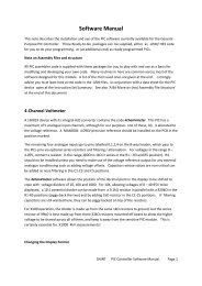
Figure 4 Spurious and Phase Noise at 70MHzIn each case resolution bandwidth is 3Hz, so the dBc/Hz value can be determined by adding 5dB to the valueread off at any particular offset from the curves. At 144MHz, for example, at 60kHz separation from thecarrier phase noise can be seen to be at a level of around -120dBc/Hz.ProgrammingThe 8 pin 16F629 PIC device has three of its connections made available to pads on the PCB. The device isconfigured for in-circuit programming to load in new firmware. Any PIC programmer such as the PicKit fromMicrochip can be connected to the PGC/PGD/PGM (Programming Clock, Data and Program) pins for chipprogramming.The PGC and PGD pads also serve as direct connection to a serial RS232 interface for controlling the chip overa 1200 baud serial interface using ASCII text based commands to send hexadecimal data for setting theregister contents. These can be taken out through feed-through capacitors, but two external resistors arerequired. A 4.7kΩ resistor is needed in series with the serial data input from the PC to prevent possible chipdamage from over current on its negative voltage excursions. On the data output to the PC, a 330Ω resistorwas needed to allow in-circuit programming. If not present, the capacitance of the feed-through wassufficient to load the programmer connected directly to the pads on the PCB and prevent it from functioning.The resistor allowed adequate isolation to let the high speed programming information past.A simple operating system is included on the PIC (in firmware named MC145170ctl.asm) that allowsinteractive setting of the registers using a terminal programme such as Hypertrm set to 1200 baud, 8 bit data,no parity, 1 stop bit. If the terminal / serial interface is connected when power is applied to the controller,the introductory message shown in the Hyperterminal screenshot below will be seen. Once connection isestablished, commands available for setting each of the three R, N and C registers within the MC145170 canbe issued. These are :Page 6