SSP 350 â The 3.0l V6 TDI engine - Volkspage
SSP 350 â The 3.0l V6 TDI engine - Volkspage
SSP 350 â The 3.0l V6 TDI engine - Volkspage
- No tags were found...
Create successful ePaper yourself
Turn your PDF publications into a flip-book with our unique Google optimized e-Paper software.
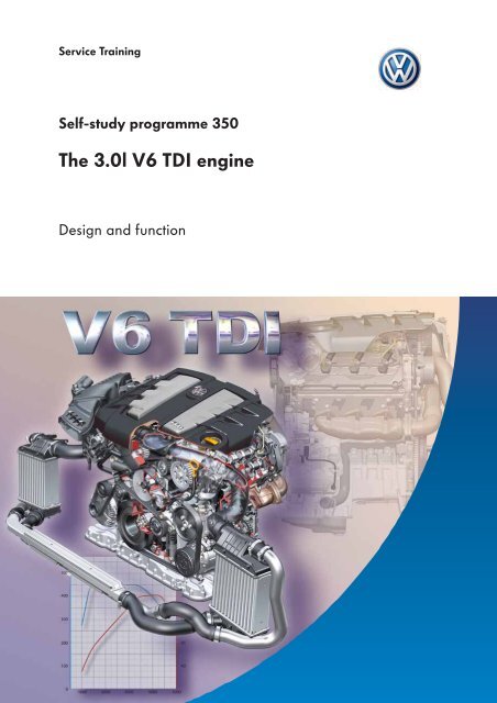
<strong>The</strong> range of <strong>engine</strong>s fitted in the Phaetonand Touareg is being extended by a hightechturbodiesel <strong>engine</strong>.<strong>The</strong> <strong>3.0l</strong> <strong>V6</strong> <strong>TDI</strong> <strong>engine</strong> has beendeveloped by Audi and is equippedwith a piezo-controlled common railfuel injection system.This unifies power and smoothness ina compact <strong>engine</strong>.<strong>The</strong> <strong>engine</strong> is combined with a dieselparticulate filter and meets the EU 4exhaust emission standard.S<strong>350</strong>_001NEWAttentionNote<strong>The</strong> self-study programme portrays the designand function of new developments!<strong>The</strong> contents will not be updated.For current testing, adjustment and repairinstructions, please refer to the customerservice literature intended for this purpose.2
Technical dataEngine code BMK (Phaeton) BKS (Touareg)Design type6-cylinder V <strong>engine</strong> (90° V angle)Displacement 2967 cm 3BoreStroke83 mm91.4 mmCompression ratio 17 : 1Valves per cylinder 4Firing sequence 1 - 4 - 3 - 6 - 2 - 5Max. output165 kW at 4000 rpmMax. torque 450 Nm at 1400 to 3250 rpm 500 Nm at 1750 to 2750 rpmEngine management systemFuelExhaust gas cleaningBosch EDC 16 C common rail fuel injection systemDiesel, at least 51 CNOxidising catalytic converter, exhaust gas recirculation, diesel particulate filterExhaust emission standard EU 4Torque and output graphTorque (Nm)Output (kW)In the Phaeton, the <strong>3.0l</strong> <strong>V6</strong> <strong>TDI</strong> <strong>engine</strong> achieves itsmaximum torque of 450 Nm as of an <strong>engine</strong> speed of1600 rpm; this is available over a wide speed range,up to 3250 rpm.In the Touareg, the <strong>engine</strong> offers maximum torque of500 Nm in the <strong>engine</strong> speed range from 1750 to2750 rpm.Its maximum output of 165 kW is achieved at4000 rpm in both vehicles.PhaetonTouaregEngine speed (rpm)S<strong>350</strong>_0405
Engine mechanical systemCylinder block<strong>The</strong> cylinder block has a 90° V angle and ismanufactured from compacted graphite iron(CGI-450).<strong>The</strong> cylinder liners are finished using the newUV photon honing process. This reduces frictionand improves running-in behaviour.S<strong>350</strong>_006Compacted graphite ironCast iron with vermicular graphite is commonlynamed as such due to its worm-like graphitestructure (worm-shaped = vermicular, Latin).In professional circles, this material is calledcompacted graphite iron (CGI).Compacted graphite iron is a high-strength materialwhich enables a thin-walled, cast iron construction.This results in a weight saving of 5 – 10 % incomparison with a grey cast iron design.S<strong>350</strong>_002Cast iron withvermicular graphiteCast iron withnodular graphiteUV photon honingWith UV photon honing<strong>The</strong> cylinder contact surface is honed in theconventional manner and is then processed usingUV photon honing.During this process, a laser beam melts the surface ofthe cylinder contact surface, and nitrogen penetratesit. This smoothes and hardens the cylinder surface.S<strong>350</strong>_056Without UV photon honing6
Bearing frameA grey cast iron bearing frame is bolted into thecrankcase. This contains the support for the crankshaftand additionally stiffens the cylinder block.S<strong>350</strong>_007Crankshaft and balancer shaft<strong>The</strong> crankshaft, which is forged from tempered steel,is supported at four points in the bearing frame.Due to the 90° V angle, the crank pins are offsetby 30°. This is necessary to achieve an even firinginterval.To ensure low-vibration <strong>engine</strong> operation, a balancershaft is located in the V of the cylinder block tocompensate the moments of inertia which occur. <strong>The</strong>balancer shaft is driven by the crankshaft via a chain.This rotates at <strong>engine</strong> speed counter to the direction inwhich the <strong>engine</strong> is running.S<strong>350</strong>_008Pistons<strong>The</strong> aluminium pistons are designed without valvepockets.<strong>The</strong> swirl is influenced by the ports in the cylinderhead and the position of the swirl flaps in the intakemodule, and ensures optimum mixture formation.To cool the piston ring zone, the pistons are equippedwith an annular cooling duct, into which oil is sprayedvia piston spray nozzles.S<strong>350</strong>_0097
Engine mechanical systemCylinder head<strong>The</strong> <strong>3.0l</strong> <strong>V6</strong> <strong>TDI</strong> <strong>engine</strong> has two cylinder headsmanufactured from aluminium alloy. Two intakeand two exhaust valves per cylinder are arrangedaccording to the principle of cross-flow.InjectorsBearing frameEach cylinder head is fitted with one camshaft forthe intake valves and one camshaft for the exhaustvalves. <strong>The</strong> intake and exhaust camshafts are linkedvia spur gear toothing with integrated backlashcompansation. <strong>The</strong> bearing frame for the camshaftsis bolted to the cylinder head.<strong>The</strong> valves are actuated via low-friction roller rockerfingers with hydraulic valve clearance compensationelements.Intake camshaftS<strong>350</strong>_010For the structure and function of thehydraulic valve clearance compensationelements, refer to self-study programmeNo. 183 "<strong>The</strong> 2.5l <strong>V6</strong> <strong>TDI</strong> 4V <strong>engine</strong>".Exhaust camshaftHydraulic valve clearancecompensationInjector<strong>The</strong> injectors are secured in the cylinder head with theaid of clamping pieces. <strong>The</strong>y can be removed viasmall covers in the cylinder head cover.Clamping pieceS<strong>350</strong>_ 0278
4-valve technologyTwo intake and two exhaust valves per cylinder arearranged vertically in the cylinder head.<strong>The</strong> vertically positioned, centrally located injectionvalve is positioned directly over the central pistonrecess. This design leads to good mixture formation,resulting in low fuel consumption and low exhaustemissions.Intake camshaftExhaust camshaftInjectorIntake valvesExhaust valvesPiston recessS<strong>350</strong>_044<strong>The</strong> shape, size and layout of the intake and exhaustports ensure good volumetric efficiency and afavourable gas cycle in the combustion chamber.Spiral port<strong>The</strong> intake ports are designed as spiral and tangentialports.Thanks to the tangential port, the inflowing airgenerates the desired, high degree of in-cylinder flow.Particularly at high speeds, the spiral port leads togood combustion chamber filling.Tangential portExhaust portS<strong>350</strong>_0159
Engine mechanical systemAir intake systemIntake manifolds with swirl flaps<strong>The</strong> intake manifolds of both cylinder banks are fittedwith continuously variable swirl flaps. Due to theposition of the swirl flaps, the intaken air's swirl isadjusted depending on the <strong>engine</strong> speed and load.Intake manifoldtop sectionIntake manifoldbottom sectionIntake manifoldflap motorV157, V275Intaken airSwirl flapsS<strong>350</strong>_016Intake manifold flap motorV157, V275<strong>The</strong> swirl flaps are moved by the intake manifold flapmotor via a push rod. To do this, the positioning motoris actuated by the <strong>engine</strong> control unit. An integratedsensor serves to feed back the current position of theswirl flaps.<strong>The</strong> intake manifold flap motors must onlybe renewed completely together with theintake manifold lower section. Pleaseobserve the notes in the workshopmanual!Swirl flapPush rodS<strong>350</strong>_04910
Function of the swirl flapsSwirl flap closedLow <strong>engine</strong> speeds<strong>The</strong> swirl flaps are closed when the <strong>engine</strong> is idlingand at low <strong>engine</strong> speeds. This causes a high levelof swirling, which leads to good mixture formation.<strong>The</strong> swirl flaps are open when the <strong>engine</strong> is started,in limp-home mode and at full throttle.S<strong>350</strong>_017Swirl flap openHigh <strong>engine</strong> speedsAs of an <strong>engine</strong> speed of approx. 1250 rpm, the swirlflaps are open continuously. Good combustionchamber filling is achieved thanks to the increasedair throughput.As of an <strong>engine</strong> speed of approx. 2750 rpm, the swirlflaps are opened completely.S<strong>350</strong>_01811
Engine mechanical systemBacklash compensation<strong>The</strong> intake and exhaust camshafts are linked via spur gear toothing with integrated backlash compansation.In this case, the exhaust camshaft's spur gear is driven by the intake camshaft's spur gear. Backlash compensationensures that the camshafts are driven with little noise.Left cylinder headSpur gearsIntake camshaftIntermediate diskS<strong>350</strong>_012S<strong>350</strong>_011Retaining ringDiaphragm springCamshaftExhaust camshaftFixedspur gearStructure<strong>The</strong> exhaust camshaft spur gear is split into two partsin the left-hand cylinder head. (<strong>The</strong> intake camshaftspur gear is split into two parts in the right-handcylinder head.)Moveablespur gear<strong>The</strong> broader part of the spur gear (fixed spur gear)is positively connected to the camshaft.Three lugs are located on the front face.<strong>The</strong> narrower part of the spur gear (moveable spurgear) can be moved radially and axially. Recesses forthe three lugs are located on its rear side.LugsS<strong>350</strong>_01912
How it works:Both spur gear parts are pushed axially togethervia the force exerted by a diaphragm spring. Whilstthis occurs, they are simultaneously caused to rotatevia the lugs.S<strong>350</strong>_020Diaphragm springBacklash compensationThis rotational movement offsets the teeth of bothspur gear parts and therefore leads to backlashcompensation between the intake and exhaustcamshafts' gear wheels.Tooth offsetS<strong>350</strong>_02113
Engine mechanical systemChain drive<strong>The</strong> camshafts, the balancer shaft and the oil pump are driven by the crankshaft via a chain drive.This is located on the <strong>engine</strong>'s gearbox side.<strong>The</strong> chain drive makes the <strong>engine</strong>'s compact design possible.Camshaft drive bank 2 – drive BCamshaft drive bank 1 – drive CCentral chain drive – drive AIntermediate gearIntermediate gearBalancer shaft driveS<strong>350</strong>_013Oil pump driveCrankshaftSecond chain drive – drive D14
<strong>The</strong> chain drive is comprised of:●A central chain from the crankshaft tothe intermediate gears (drive A),<strong>The</strong> camshaft chain sprockets have the same diameteras the crankshaft sprocket.<strong>The</strong> necessary camshaft: crankshaft ratio of 2 : 1 isachieved by means of the intermediate gears.●A chain from each of the intermediate gears tothe intake camshafts (drives B and C),<strong>The</strong> chains are tensioned by sprung, hydraulic chaintensioners; this system is maintenance-free.●A chain from the crankshaft to the oil pump driveand to the balancershaft.Ancillary component drive<strong>The</strong> coolant pump, the power steering pump, the airconditioner compressor and the alternator are drivenby the crankshaft via a poly V-belt.Coolant pumpPower steering pumpAlternatorPoly V-beltHydraulic tensionerS<strong>350</strong>_022Air conditionercompressor15
Engine mechanical systemLubrication systemOverview of the systemOil filter moduleVacuum pumpTurbochargerOil coolerOil returnS<strong>350</strong>_023Oil spray nozzles(piston cooling)Pressure relief valveOil panOil pumpOil pressureregulating valveOil level and oil temperaturesender G266Oil without pressureOil under pressure16
Oil filter module<strong>The</strong> oil filter module contains an oil non-return valveand the short-circuit valve. <strong>The</strong> oil non-return valveprevents oil from flowing back into the oil pan fromthe oil filter housing when the <strong>engine</strong> is switched off.<strong>The</strong> short-circuit valve is a bypass valve, which openswhen the oil filter or oil cooler is blocked and therebyensures that the <strong>engine</strong> is supplied with oil.It opens at 2.5 bar.Oil pressure regulating valveOil spray nozzlesOil is sprayed into the pistons' cooling ducts via the oilspray nozzles. This cools the pistons.Pressure relief valveThis is a safety valve in the oil pump. It protects thelubrication system from excessive pressure on coldstarting.It opens at 11 bar.<strong>The</strong> oil pressure regulating valve is integrated into theoil pump and regulates the <strong>engine</strong>'s oil pressure.17
Engine mechanical systemOil pan<strong>The</strong> oil pan is comprised of two components; a cast aluminium upper oil pan section and a sheet steel lower oil pansection.<strong>The</strong> design of the oil pan differs in the Phaeton and the Touareg. This is the result of installation space conditionsand off-road capability requirements. <strong>The</strong> oil pump's oil intake system has accordingly been adapted to thedifferent design forms.Oil pan top sectionPhaeton oil panDue to the limited installation space, the oil pan fittedin the Phaeton flattens and broadens at the bottom.Oil pan lower sectionS<strong>350</strong>_014Oil pan top sectionTouareg oil pan<strong>The</strong> design of the oil pan fitted in the Touareg isnarrow and deep. Due to the low oil intake point and,in comparison with the Phaeton, lower oil level,guaranteed oil intake with little oil foaming isachieved on gradients.S<strong>350</strong>_026Oil pan lower section18
Oil pump<strong>The</strong> oil pump is a crescent pump. It operatesaccording to the duocentric principle and is drivenby chain drive D via a stub shaft.<strong>The</strong> length of the intake fitting has been adapted tothe different oil pan designs.PhaetonTouaregIntake fittingS<strong>350</strong>_024Oil filter module<strong>The</strong> oil filter module is located in the V of the <strong>engine</strong>.<strong>The</strong> oil filter, the oil cooler and the cyclonic oilseparator with pressure control valve for thecrankcase breather system are integrated intothe oil filter module.Oil filterCyclonic oil separator withpressure control valve<strong>The</strong> oil cooler is connected to the <strong>engine</strong>'s coolantcircuit.S<strong>350</strong>_025Oil cooler19
Engine mechanical systemCrankcase breather systemIn combustion <strong>engine</strong>s, pressure differences betweenthe combustion chamber and crankcase lead to airflows between the piston rings and cylinder contactsurface; these are called blow-by gases.To prevent environmental pollution, these gases,which contain oil, are fed back to the intake area viathe crankcase breather system.A cyclonic oil separator separates the oil contained inthe gases from the air. This oil is returned to the oilpan via a port in the crankcase.Pressure control valveCyclonic oil separatorFunctional principleTurbochargerS<strong>350</strong>_029Charge air coolerPressure control valveBlow-by gasesCyclonic oil separatorS<strong>350</strong>_06620
Function of the cyclonic oil separator<strong>The</strong> blow-by gases are fed to the cyclonic oilseparator via a port inside the <strong>engine</strong>.To the intake portPressure control valveCyclonic oil separator<strong>The</strong> cyclonic oil separator causes the air to rotate. Dueto the centrifugal force which occurs, the oil spray isspun onto the wall of the separator.Oil droplets form there, and these flow off into the oilpan via a port in the crankcase. <strong>The</strong> air, from whichthe oil spray has been removed, is fed back into theintake port via the pressure control valve.From the crankcaseS<strong>350</strong>_030Pressure control valve openFunction of the pressure control valve<strong>The</strong> pressure control valve is located in the cover ofthe cyclonic oil separator. It is comprised of amembrane and a pressure spring, and regulates thepressure for venting the crankcase.To the intake portDiaphragmsCompressionspringWhen the blow-by gases are introduced, the pressurecontrol valve limits the vacuum in the crankcase, as<strong>engine</strong> gaskets may become damaged if there is anexcessive vacuum.If the vacuum in the intake port is high, the pressurecontrol valve closes. In the case of a low vacuum inthe intake port, it opens by means of the pressurespring's force.From the crankcasePressure control valve closedS<strong>350</strong>_050S<strong>350</strong>_03421
Engine mechanical systemCoolant circuitOverview of the system2 34171618110111914121513920987Engine coolant circuitCoolant circuit for fuel cooling(Touareg only)HotHotColdCold1234567Cooler for <strong>engine</strong> coolant circuitGearbox oil coolerAlternatorContinued coolant circulation pump V51(with towing attachment only)Air reservoirHeat exchangerExpansion tank8910111213Additional heaterChokeOil coolerCooler for exhaust gas recirculationExhaust gas recirculation flap<strong>The</strong>rmostat (opens as of a coolanttemperature of 87 °C)22
Coolant circuit for fuel cooling(Touareg only)56In the Touareg, the <strong>3.0l</strong> <strong>V6</strong> <strong>TDI</strong> <strong>engine</strong> is equippedwith a separate coolant circuit for the fuel cooler.This is necessary because the temperature of thecoolant is too high, when the <strong>engine</strong> is at operatingtemperature, to cool the returning fuel.Water pump V36 (Touareg only)21<strong>The</strong> water pump V36 is an electric circulation pump. Itis initialised as required by the <strong>engine</strong> control unit,and ensures that the coolant is circulated in thecoolant circuit in order to cool the fuel.Continued coolant circulation pump V51(vehicles with towing attachment only)6<strong>The</strong> continued coolant circulation pump V51 is anelectrically driven pump. It is initialised according to aperformance map by the <strong>engine</strong> control unit, andtherefore ensures that the coolant is circulated forcooling purposes when the <strong>engine</strong> is "off".S<strong>350</strong>_0281415161718192021Coolant pumpCoolant temperature sender G62Radiator outlet coolant temperature sender G83Water pump V36Cooler for fuel coolingFuel coolerNon-return valveHeating23
Injectors (piezo injectors)<strong>The</strong> <strong>3.0l</strong> <strong>V6</strong> <strong>TDI</strong> <strong>engine</strong> is fitted with piezo-controlled injectors. In comparison with solenoid valve-controlledinjectors, piezo technology has approximately 75 % less moved mass at the injector needle.This weight reduction offers the following advantages:●●●Very short switching timesSeveral injections per working cycle are possiblePrecisely apportionable injection quantities<strong>The</strong> injection process, with a total of up to five partial injections per working cycle, has up to two pilot injections inthe lower <strong>engine</strong> speed range and two secondary injections. This enables low emissions and smooth combustion.Piezo effect(Piezo [Greek] = pressure)<strong>The</strong> piezo-electric effect was discovered byPierre Curie in 1880.If a crystalline lattice (turmaline, quartz) comprised ofions is deformed under pressure, electrical voltage isgenerated.<strong>The</strong> piezo-electric effect can also be reversed byapplying an electric voltage. In this case, the crystalexpands. This effect is used to control the injectors.Piezo actuatorConnecting pistonValve pistonCaution! <strong>The</strong> piezo-controlled injectorsare actuated with a voltage of110 – 148 V. Observe the safetyinstructions in the workshop manual!Switching valveInjector needleS<strong>350</strong>_03225
Engine mechanical systemFuel systemOverview of the system<strong>The</strong> fuel system is sub-divided into three pressureranges:●●●Supply and return pressureReturn pressure between the injectors and pressureretention valveHigh pressureIn the fuel supply system, the fuel is delivered to thehigh-pressure pump from the fuel tank via the fuelfilter by the pressurisation pump and the mechanicalgear pump. <strong>The</strong> high fuel pressure required forinjection is generated in the high-pressure pump andis fed into the high-pressure accumulator (rail).High-pressure pumpMechanicalgear pumpFuel metering valve N290Pressure retention valveFuel temperaturesender G81High pressure 300 – 1600 barReturn pressure between injectorsand pressure retention valve 10 barFuel filterSupply pressureReturn pressurePre-heater valve(expansion element)26
From the high-pressure accumulator, the fuel isforwarded to the injectors, which inject it into thecombustion chambers.<strong>The</strong> pressure retention valve maintains the injectors'return pressure of 10 bar. This pressure is required forthe piezo injectors' function.Fuel pressure sender G247High-pressure accumulator (rail), cylinder bank 24 5 6ChokeHigh-pressure accumulator (rail), cylinder bank 11 2 3Fuel pressure regulatingvalve N276Piezo injectors 1 – 3N30, N31, N32In the Phaeton, the fuel is cooled bymeans of a fuel-air cooler on the vehiclefloor.Fuel-coolant cooler(Touareg)Fuel tankFuel system pressurisationpump G6S<strong>350</strong>_03327
Engine mechanical systemExhaust system<strong>The</strong> <strong>3.0l</strong> <strong>V6</strong> <strong>TDI</strong> <strong>engine</strong>'s exhaust system is comprised of an electrically adjustable turbocharger, an oxidisingcatalytic converter located beneath the bonnet, a diesel particulate filter, two rear silencers and an exhaust gasrecirculation system with switchable exhaust gas recirculation cooler.<strong>The</strong> Figure shows the exhaust system fitted in the Phaeton.Adjustable turbochargerExhaust gas recirculationvalve with exhaust gasrecirculation coolerOxidising catalytic converterDiesel particulate filterS<strong>350</strong>_047Rear silencers28
TurbochargerIn the <strong>3.0l</strong> <strong>V6</strong> <strong>TDI</strong> <strong>engine</strong>, the charge pressure is generated by an adjustable turbocharger.This is equipped with adjustable guide vanes, which enable the flow of exhaust gas onto the turbine impeller to beinfluenced. <strong>The</strong> advantage of this is that optimal charge pressure and therefore good combustion are achievedthroughout the entire <strong>engine</strong> speed range. In the lower <strong>engine</strong> speed range, the adjustable guide vanes offer hightorque and good starting behaviour; in the upper <strong>engine</strong> speed range, they enable low fuel consumption and lowemission values.<strong>The</strong> guide vanes are adjusted via an electric positioning motor. Electric initialisation makes fast turbochargerresponse behaviour and precise regulation possible.An exhaust gas temperature sender is located upstream of the turbocharger. <strong>The</strong> <strong>engine</strong> control unit uses theexhaust gas temperature sender's signal to protect the turbocharger from impermissibly high exhaust gastemperatures. In the event of excessive exhaust gas temperatures, e.g. during full-throttle operation, the <strong>engine</strong>output is reduced.Guide vane adjustmentPositioning motorGuide vanesTurbocharger 1control unit J724Exhaust gas temperaturesender 1 G235S<strong>350</strong>_043<strong>The</strong> principle of the adjustable turbocharger is explained in self-study programme No. 190"Adjustable turbocharger".29
Engine mechanical systemExhaust gas recirculationThanks to exhaust gas recirculation, part of theexhaust gases are returned to the combustion process.<strong>The</strong> reduction in the fuel-air mixture's oxygenconcentration which is achieved in this process slowscombustion down. This leads to a reduction in thepeak combustion temperature and therefore reducesnitrogen oxide emissions.<strong>The</strong> quantity of exhaust gas which is recirculated iscontrolled by the exhaust gas recirculation valveaccording to a performance map in the <strong>engine</strong>control unit.An exhaust gas recirculation cooler ensures that thecombustion temperature is additionally lowered bycooling the recirculated exhaust gases, and that anincreased quantity of exhaust gases can berecirculated.Exhaust gas recirculation valveCoolant connectionsExhaust gasrecirculationcoolerExhaustgasBypass valve for exhaustgas recirculation coolerChargeairS<strong>350</strong>_065Exhaustgas30
Exhaust gas cooling switched offUp to a coolant temperature of 60 °C, the bypassvalve remains open and the exhaust gas is conductedpast the cooler.As a result of this, the <strong>engine</strong> and catalytic converterreach their relevant operating temperature within ashort time.Diesel direct injectionsystem control unit J248Exhaust gasrecirculation valve N18Exhaust gasrecirculation valveCoolerVacuum unitBypass valveS<strong>350</strong>_045Exhaust gas cooling switched onAs of a coolant temperature of 60 °C, the bypassvalve is closed by the change-over valve.Cooler<strong>The</strong> recirculated exhaust gas is thereby conducted tothe exhaust gas recirculation valve via the cooler.Exhaust gasrecirculation coolerchange-over valve N345Vacuum unitBypass valveS<strong>350</strong>_046In the following cases, the bypass valve is also switched when the <strong>engine</strong> is at operating temperature:<strong>The</strong> bypass valve is opened during idling to maintain the oxidising catalytic converter's operatingtemperature.During deceleration, the bypass valve is switched back and forth once to guarantee unimpeded valvemovement.31
Engine mechanical systemDiesel particulate filterIn the <strong>3.0l</strong> <strong>V6</strong> <strong>TDI</strong> <strong>engine</strong>, carbon particulate emissions are additionally reduced by means of a diesel particulatefilter in addition to measures implemented inside the <strong>engine</strong>. This diesel particulate filter is located in the exhaustsystem downstream of the oxidising catalytic converter which is positioned under the bonnet.Oxidising catalytic converterCatalytically coatedparticulate filterS<strong>350</strong>_035Overview of the system213124579101168S<strong>350</strong>_068123456Control unit with display in dash panel insert J285Diesel direct injection systemcontrol unit J248Air mass meter G70Diesel <strong>engine</strong>Exhaust gas temperature sender 1 G235Turbocharger789101112Lambda probe G39Oxidising catalytic converterCatalytic converter temperature sensor 1 G20(Phaeton only)Bank 1 exhaust gas temperature sender 2 G448Particulate filterExhaust gas pressure sensor 1 G45032
Structure<strong>The</strong> diesel particulate filter is comprised of ahoneycombshaped ceramic body manufactured fromsilicon carbide, which is contained in a metal housing.<strong>The</strong> ceramic body is sub-divided into a multitude ofsmall channels, which are sealed on alternating sides.This results in intake and exhaust channels which areseparated by filter walls.<strong>The</strong> silicon carbide filter walls are porous and arecoated with a substrate comprised of aluminium oxideand cerium oxide. <strong>The</strong> precious metal platinum, whichserves as the catalyst, is vapour-deposited onto thissubstrate.<strong>The</strong> cerium oxide coating in the particulate filterlowers the carbon's ignition temperature andaccelerates the thermal reaction with oxygen.Connections for exhaust gaspressure sensor 1 G450Bank 1 exhaust gas temperaturesender 2 G448S<strong>350</strong>_062Metal housingCeramic bodyFunction<strong>The</strong> exhaust gas, which contains carbon, flowsthrough the intake channels' filter walls. Unlike thegaseous components of the exhaust gas, the carbonparticles are retained in the intake channels.S<strong>350</strong>_03633
Engine mechanical systemRegenerationTo prevent the particulate filter from becoming blocked with carbon particles, thereby impeding its function, it mustbe regularly regenerated. During the regeneration process, the carbon particles which have collected in theparticulate filter are burned (oxidised).During regeneration of the catalytically coated particulate filter, a distinction is made between passive and activeregeneration. This process is imperceptible to the driver.Passive regenerationDuring passive regeneration, the carbon particles arecontinuously combusted without <strong>engine</strong> managementsystem intervention. This is primarily carried out athigh <strong>engine</strong> loads, e.g. motorway driving, at exhaustgas temperatures of <strong>350</strong> – 500 °C.In this case, the carbon particles are converted tocarbon dioxide via a reaction with nitrogen dioxide.Active regenerationIn urban traffic, i.e. low <strong>engine</strong> load, the exhaust gastemperatures are too low for passive regeneration. Asno further carbon particles can be degraded, thecarbon accumulates in the filter.As soon as a specific level of carbon has beenreached in the filter, active regeneration is introducedby the <strong>engine</strong> management system. This process takesapproximately 10 – 15 minutes. <strong>The</strong> carbon particlesare combusted together with oxygen at an exhaustgas temperature of 600 – 650 °C to form carbondioxide.34
Active regeneration function<strong>The</strong> particulate filter's carbon level is calculated by two pre-programmed level models in the <strong>engine</strong> control unit.One carbon level model is determined from the user's driving style and the exhaust gas temperature sensor andlambda probe signals. <strong>The</strong> other carbon level model is the diesel particulate filter's flow resistance, which iscalculated from the signals output by exhaust gas pressure sensor 1, bank 1 exhaust gas temperature sender 2and the air mass meter.Air mass meter G70Exhaust gas pressuresensor 1 G450Bank 1 exhaust gastemperature sender 2 G448Diesel direct injection systemcontrol unit J248Diesel particulate filterS<strong>350</strong>_037As soon as the carbon level limit value has been reached in the particulate filter, active regeneration is introducedby the <strong>engine</strong> management system. <strong>The</strong> following measures lead to a specific, temporary increase in exhaust gastemperature to approximately 600 – 650 °C. In this temperature range, the carbon collected in the particulate filteroxidises to form carbon dioxide.●<strong>The</strong> intake air supply is regulated via the electricthrottle valve.S<strong>350</strong>_041●Exhaust gas recirculation is switched off to increasethe combustion temperature and the oxygencontent in the combustion chamber.S<strong>350</strong>_03835
Engine mechanical system●Shortly after "retarded" main injection, the firstsecondary injection is introduced to increase thecombustion temperature.S<strong>350</strong>_039●Further secondary injection is introduced long aftermain injection. This fuel does not combust in thecylinder, but evaporates in the combustionchamber. <strong>The</strong> uncombusted hydrocarbonscontained in this fuel vapour are oxidised in theoxidising catalytic converter. <strong>The</strong> heat which isgenerated during this process increases theexhaust gas temperature upstream of theparticulate filter to approximately 620 °C.<strong>The</strong> <strong>engine</strong> control unit uses the signals transmittedby the bank 1 exhaust gas temperature sender 2(Touareg) or catalytic converter temperaturesensor 1 (Phaeton) to calculate the injectionquantity for retarded secondary injection.S<strong>350</strong>_069●<strong>The</strong> charge pressure is adapted to prevent thedriver from noticing a perceptible change in torqueduring the regeneration process.S<strong>350</strong>_04236
Diesel particulate filter warning lamp K231In the event of extreme, short-distance operation,regeneration of the diesel particulate filter may beimpeded, because the exhaust gas temperature failsto achieve the required temperature value. Asregeneration is unable to take place, filter damageor blockage due to carbon overloading is possible.To avoid cases such as these, the diesel particulatefilter warning lamp in the dash panel insert lights up ifthe carbon level has reached a certain limit value.S<strong>350</strong>_070Via this signal, the driver is requested to drive atincreased speed for a short period of time.<strong>The</strong> warning lamp must go out following this measure.If the diesel particulate filter warning lamp does notgo out despite this measure, the glow period warninglamp lights up. <strong>The</strong> text "Engine malfunction -workshop" appears in the dash panel insert display.<strong>The</strong> driver is thereby requested to seek the nextworkshop.For detailed information on drivingbehaviour when the diesel particulatefilter warning lamp lights up, pleaserefer to the owner's manual.A detailed description of the diesel particulate filter system can be found in self-study programmeNo. 336 "<strong>The</strong> catalytically coated diesel particulate filter".37
Engine management systemOverview of the systemSensorsAir mass meter G70Engine speed sender G28Hall sender G40Coolant temperature sender G62Radiator outlet coolant temperaturesender G83Fuel temperature sender G81Fuel pressure sender G247CANdata busAccelerator position sender G79Accelerator position sender 2 G185Lambda probe G39Brake light switch FBrake pedal switch F47Clutch pedal switch F36Diesel direct injectionsystem control unit J248Catalytic converter temperature sensor 1 G20(Phaeton only)Exhaust gas temperature sender 1 G235DiagnosticconnectionBank 1 exhaust gas temperaturesender 2 G448Exhaust gas pressure sensor 1 G450Intake air temperature sender G42Charge air pressure sender G3138
ActuatorsIntake manifold flap motor V157Intake manifold flap 2 motor V275Automatic glow periodcontrol unit J179Injectors for cylinders 1 – 6N30, N31, N32, N33, N83 and N84Glow plugs 1 – 6Q10, Q11, Q12, Q13, Q14 and Q15Throttle valve module J338Fuel pressure regulating valve N276Exhaust gas recirculation valve N18Exhaust gas recirculation cooler changeovervalve N345Radiator fan control unit J293Radiator fan control unit 2 J671Radiator fan V7Radiator fan 2 V177Left electrohydraulic <strong>engine</strong> mountingsolenoid valve N144 (Phaeton only)Lambda probe heater Z19Fuel pump relay J17 forfuel pumps G6 and G23Turbocharger 1 control unit J724Fuel metering valve N290S<strong>350</strong>_04839
ServiceSpecial toolsDesignation Tool UseT40049AdapterFor turning the crankshaft over.S<strong>350</strong>_059T40055SocketFor loosening and tighteningthe union nut connection onhigh-pressure pipes in thecommon rail fuel injectionsystem.S<strong>350</strong>_051T40058AdapterFor turning the crankshaft over.S<strong>350</strong>_058T40060Adjustment pinFor securing the camshaftswhen adjusting valve timing.S<strong>350</strong>_060T40061AdapterFor correcting the position ofthe camshafts when adjustingthe valve timing.S<strong>350</strong>_06140
Designation Tool UseT40062AdapterFor tensioning the chainsprocket when adjusting valvetiming.S<strong>350</strong>_057T40094Camshaft insert toolFor installing the camshafts.S<strong>350</strong>_052T40094/1 and T40094/2SupportFor installing the camshafts.S<strong>350</strong>_055T40095BracketFor installing the camshafts.S<strong>350</strong>_054T40096TensionerFor installing the camshafts.S<strong>350</strong>_05341
Test your knowledgeWhich are the correct answers?One, several or all answers may be correct.1. What is the task of camshaft spur gear backlash compensation?a) Backlash compensation ensures that the camshafts are driven with little noise.b) Backlash compensation ensures that the intake camshaft is adjusted at high<strong>engine</strong> speeds.c) Backlash compensation ensures rigid <strong>engine</strong> speed compensation between the gearson the intake and exhaust camshaft.2. What do the swirl flaps in the intake manifold do?a) <strong>The</strong> swirl flaps interrupt the supply of air in the intake port. Due to this, less airis intaken and compressed, as a result of which <strong>engine</strong> coasting is gentle.b) Due to the position of the swirl flaps, air movement in the intake swirl port is adapted to the<strong>engine</strong> speed.c) In certain <strong>engine</strong> operating states, the swirl flaps generate a difference between theintake manifold pressure and exhaust gas pressure. This guarantees effective exhaust gasrecirculation.3. In the timing chain drive, how is the necessary camshaft : crankshaft ratio of 2 : 1 achieved?a) Via hydraulic chain tensioners.b) Via intermediate gears.c) Via the length of the timing chains.4. Which statement regarding the diesel particulate filter system fitted in the <strong>3.0l</strong> <strong>V6</strong> <strong>TDI</strong> <strong>engine</strong> in thePhaeton and Touareg is correct?a) An oxidising catalytic converter and a catalytically coated diesel particulate filter are combined inone component and located beneath the bonnet.b) A catalytically coated diesel particulate filter is located in the exhaust system below the vehiclefloor.c) <strong>The</strong> <strong>3.0l</strong> <strong>V6</strong> <strong>TDI</strong> <strong>engine</strong> has a diesel particulate filter system which is supported by an additive.42
Solutions:1. a; 2. b; 3. b; 4. b43
<strong>350</strong>© VOLKSWAGEN AG, WolfsburgAll rights and technical changes reserved.000.2811.64.20 Technical status 03.2005Volkswagen AGService Training VK-21Brieffach 1995D-38436 Wolfsburg❀ This paper has been manufactured from cellulose bleached without the use of chlorine.


