Technical Data Lambda-Transmitter LT 1 - lamtec
Technical Data Lambda-Transmitter LT 1 - lamtec
Technical Data Lambda-Transmitter LT 1 - lamtec
- No tags were found...
Create successful ePaper yourself
Turn your PDF publications into a flip-book with our unique Google optimized e-Paper software.
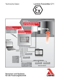
Connection DiagramRelay Modul for Digital Outputs Extern<strong>LT</strong> 1 <strong>Lambda</strong> <strong>Transmitter</strong> RS 422LAMTEC SYSTEMBUS (CAN bus)until March 2001RS 422 / LAMTEC SYSTEM BUS(floating potential)(1)+24 VDigital inputs24 V, ca. 6 mABridge BR 231 to powerelectronics, see 5.1.1 in theOperating instructionsClosed - referenced to theunit's voltageOpen - floating potential forexternal voltagesource757473727150696867666564636261T X DT X D (+)R X D (+)R X DGNDInput 8Input 7Input 5Input 4Input 3Input 2Input 1GNDCAN LowCAN HighCAN LowCAN HighCAN GND24 V DC +(1)Digital outputs(relay drivers/opencollector)+24 V DCSwitching current25 mA max.+24 VGND59585756551234External relay moduleType 6 60 R 0012 (optional)Max. 230 V AC, 4Ad 1d 2d 3Output 7Output 6Output 5+24 Vsince March 2001 theterminals 51-54 and 56-59are dropped. After thisrelay module is attached bya flat cable, see page 13545352511234External relay moduleType 6 60 R 0012 (optional)Max. 230 V AC, 4Ad 1d 2d 3Output 4Output 3Output 2Interface modules:Connector for 25 pininterface moduleRS 232 Only in conjunction with Remote-Display-software 6 63 P 0600RS 422/485 6 63 P 0503(1)Not available in OEM version


