Atlas A Manual - Ferroli
Atlas A Manual - Ferroli
Atlas A Manual - Ferroli
- No tags were found...

You also want an ePaper? Increase the reach of your titles
YUMPU automatically turns print PDFs into web optimized ePapers that Google loves.
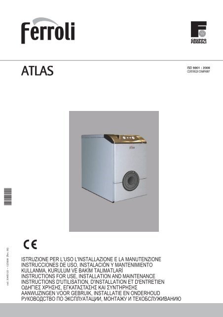
ATLAScod. 3540S122 — 12/2009 (Rev. 00)ISTRUZIONE PER L’USO L'INSTALLAZIONE E LA MANUTENZIONEINSTRUCCIONES DE USO, INSTALACIÓN Y MANTENIMIENTOKULLANMA, KURULUM VE BAKM TALIMATLARINSTRUCTIONS FOR USE, INSTALLATION AND MAINTENANCEINSTRUCTIONS D'UTILISATION, D'INSTALLATION ET D'ENTRETIEN , AANWIJZINGEN VOOR GEBRUIK, INSTALLATIE EN ONDERHOUD ,
ATLASEN1. GENERAL INSTRUCTIONS• Carefully read the instructions contained in this instruction booklet.• After boiler installation, inform the user regarding its operation and give him thismanual, which is an integral and essential part of the product and must be kept withcare for future reference.• Installation and maintenance must be carried out by professionally qualified personnel,according to current regulations and the manufacturer's instructions. Do not carryout any operation on the sealed control parts.• Incorrect installation or inadequate maintenance can result in damage or injury. TheManufacturer declines any liability for damage due to errors in installation and useor failure to follow the instructions.• Before carrying out any cleaning or maintenance operation, disconnect the unit fromthe power supply using the system switch and/or the special cut-off devices.• In case of a fault and/or poor operation, deactivate the unit and do not attempt torepair it or directly intervene. Contact professionally qualified personnel. Repair/replacementof the products must only be carried out by professionally qualified usingoriginal spare parts. Failure to comply with the above could affect the safety of theunit.• This unit must only be used for its intended purpose. Any other use is consideredimproper and therefore dangerous.• The packing materials are potentially hazardous and must not be left within thereach of children.• The images given in this manual are a simplified representation of the product. Inthis representation there may be slight and insignificant differences with respect tothe product supplied.2. OPERATING INSTRUCTIONS2.1 IntroductionDear Customer,Thank you for choosing a FERROLI boiler featuring advanced design, cutting-edgetechnology, high reliability and quality construction. Please read this manual carefullysince it provides important information on safe installation, use and maintenance.ATLAS is a high-efficiency heat generator for the production of heating hot water, suitablefor operation with blown oil or gas burners. The boiler shell consists of cast iron elements,assembled with steel stays and double cones, whose profile is specially designedwith optimum division of the fins, offering high thermal efficiency and therefore high energy-saving.2.2 Control panel20fig. 1 - Control panel for models ATLAS 32-78fig. 2 - Control panel for models ATLAS 95Key1 = Thermohydrometer2 = On switch3 = <strong>Manual</strong>-reset safety thermostat4 = 1st stage temperature adjustment knob5 = 2nd stage temperature adjustment knob2.3 Turning on and offBoiler lightingOpen the fuel shutoff valves.Switch on the power to the unit.Press button 2 of fig. 1 to feed the boiler and burner. Refer to the burner manual for operation.Turning the boiler off1 2 3 4204060800 120°C100°C 030 601 4 5 3 240600 120°C80100°C30060 30 6090 0For brief shutdown periods just press button 2 of fig. 1 on the control panel , bringing itto position “0”. For long shutdown periods, as well as operating button 2 also close thefuel shutoff valve . To avoid damage caused by freezing during long shutdowns in winter,add a suitable antifreeze to the system or completely drain the system.9090onoff2.4 AdjustmentsHeating temperature settingSet the required system temperature with the control thermostat 4 of fig. 1.For the model ATLAS 95, with the control thermostat 5 then set the temperature of the2nd stage to a temperature 10°C lower than that of the 1st stage.AIMPORTANT: The temperature setting of the 2nd stage must always belower than that of the 1st stage..fig. 3 - Temperature adjustment for model ATLAS 95Room temperature adjustment (with optional room thermostat)Using the room thermostat, set the temperature desired in the rooms. If the room thermostatis not installed the boiler will keep the heating system at its setpoint temperature.3. INSTALLATION3.1 General InstructionsBOILER INSTALLATION MUST ONLY BE PERFORMED BY QUALIFIED PERSON-NEL, IN ACCORDANCE WITH ALL THE INSTRUCTIONS GIVEN IN THIS TECHNICALMANUAL, THE PROVISIONS OF CURRENT LAW, THE PRESCRIPTIONS OF NA-TIONAL AND LOCAL STANDARDS AND THE RULES OF PROPER WORKMANSHIP.3.2 Place of installationThe boiler must be installed in a special room with ventilation openings towards the outsidein conformity with current regulations. If there are several burners or extraction unitsthat can work together in the same room, the ventilation openings must be sized for simultaneousoperation of all the units. The place of installation must be free of flammableobjects or materials, corrosive gases, volatile substances or dusts which, sucked by theburner fan, can obstruct the pipes inside the burner or the combustion head. The roommust be dry and not exposed to rain, snow or frost.AIf the unit is enclosed in a cabinet or mounted alongside, a space must be providedfor removing the casing and for normal maintenance operations. In particular,after boiler installation with burner on the front door, make sure the frontdoor can open freely without the burner striking walls or other obstacles.3.3 Plumbing connectionsThe heating capacity of the unit must be previously established by calculating the building'sheat requirement according to current regulations. The system must be providedwith all the components for correct and regular operation. It is advisable to install shutoffvalves between the boiler and heating system allowing the boiler to be isolated from thesystem if necessary.BThe safety valve outlet must be connected to a funnel or collection pipe to preventwater spurting onto the floor in case of overpressure in the heating circuit.Otherwise, if the discharge valve cuts in and floods the room, the boiler manufacturercannot be held liable.Do not use the water system pipes to earth electrical appliances.Before installation, carefully wash all the pipes of the system to remove any residuals orimpurities that could affect proper operation of the unit.Carry out the relevant connections according to the diagram in and thecap. 5 symbolsgiven on the unit.AThe unit is not supplied with an expansion tank; its connection must thereforebe carried out by the installer. The pressure in the system, when cold, must be1 bar.Water system characteristics-10°C60 604 5In the presence of water harder than 25° Fr (1°F = 10ppm CaCO3), use suitably treatedwater in order to avoid possible scaling in the boiler. Treatment must not reduce the hardnessto values below 15°F (Decree 236/88 for uses of water intended for human consumption).Treatment of the water used is indispensable in case of very large systemsor with frequent introduction of replenishing water in the system.BIf water softeners are installed at the boiler cold water inlet, make sure not toreduce the water hardness too much, as this could cause early deterioration ofthe magnesium anode in the hot water tank.cod. 3540S122 - 12/2009 (Rev. 00)EN17
ATLASAntifreeze system, antifreeze fluids, additives and inhibitorsThe boiler is equipped with an antifreeze system that turns on the boiler in heating modewhen the system delivery water temperature falls under 6°C. The device will not comeon if the electricity and/or gas supply to the unit are cut off. If it becomes necessary, it ispermissible to use antifreeze fluid, additives and inhibitors only if the manufacturer ofthese fluids or additives guarantees they are suitable for this use and cause no damageto the heat exchanger or other components and/or materials of the boiler unit and system.It is prohibited to use generic antifreeze fluid, additives or inhibitors that are not expresslysuited for use in heating systems and compatible with the materials of the boilerunit and system.3.4 Burner connectionAn oil or gas burner, with blown air for pressured furnaces, can be used if its operationcharacteristics are suitable for the size of the boiler furnace and its overpressure. Thechoice of burner must be made beforehand, following the manufacturer's instructions,according to the work range, fuel consumption and pressures, as well as the length ofthe firebox. Install the burner in compliance with the Manufacturer's instructions.3.5 Electrical connectionsConnection to the electrical gridBThe unit's electrical safety is only guaranteed when correctly connected to anefficient earthing system executed according to current safety standards. Havethe efficiency and suitability of the earthing system checked by professionallyqualified personnel. The manufacturer is not responsible for any damagecaused by failure to earth the system. Also make sure that the electrical systemis adequate for the maximum power absorbed by the unit, as specified on theboiler dataplate.The boiler is prewired and provided with a Y-cable and plug for connection to the electricityline. The connections to the grid must be made with a permanent connection andequipped with a bipolar switch whose contacts have a minimum opening of at least 3mm, interposing fuses of max. 3A between the boiler and the line. It is important to respectthe polarities (LINE: brown wire / NEUTRAL: blue wire / EARTH: yellow-greenwire) in making connections to the electrical line. During installation or when changingthe power cable, the earth wire must be left 2 cm longer than the others.BThe user must never change the unit's power cable. If the cable gets damaged,switch off the unit and have it changed solely by professionally qualified personnel.If changing the electric power cable, use solely “HAR H05 VV-F” 3x0.75mm2 cable with a maximum outside diameter of 8 mm.Accessing the electrical terminal blockUndo the two screws “A” located on the top part of the control panel and remove thecover “B“.3.6 Connection to the fluefig. 4 - Accessing the terminal blockThe unit must be connected to a flue designed and built in compliance with current regulations.The pipe between the boiler and flue must be made from material suitable forthe purpose, i.e. heat and corrosion resistant. Ensure the seal at the joints and insulatethe entire pipe between boiler and flue, to prevent the formation of condensate.4. SERVICE AND MAINTENANCEAll adjustment, conversion, start-up and maintenance operations described below mustonly be carried out by Qualified Personnel (meeting the professional technical requirementsprescribed by current regulations) such as those of the Local After-Sales TechnicalService.FERROLI declines any liability for damage and/or injury caused by unqualified and unauthorisedpeople tampering with the unit.4.1 AdjustmentsBurner adjustmentA12Boiler efficiency and correct operation depend above all on accurate burner adjustments.Carefully follow the Manufacturer's instructions. The two-stage burners must have thefirst stage adjusted to a power level not below the boiler's rated min. power. The powerof the second stage must not be higher than the boiler's rated max. power.B4.2 Start-upBChecks to be made at first lighting and after all maintenance operations that involveddisconnecting from the systems or an operation on safety devices orparts of the boiler:Before lighting the boiler• Open any on-off valves between the boiler and the systems.• Check the seal of the fuel system.• Check correct prefilling of the expansion tank.• Fill the water system and make sure that all air contained in the boiler and the systemhas been vented, by opening the air valve on the boiler and any air valves onthe system.• Make sure there are no water leaks in the system, domestic hot water circuits, connectionsor boiler.• Check correct connection of the electrical system and efficiency of the earthing system• Make sure there are no flammable liquids or materials in the immediate vicinity ofthe boilerChecks during operation• Light the unit on as described in sec. 2.3.• Make sure the fuel circuit and water systems are tight.• Check the efficiency of the flue and air/fume ducts while the boiler is working.• Make sure the water is circulating properly between the boiler and the systems.• Check proper lighting of the boiler by doing several tests, turning it on and off withthe room thermostat or remote control.• Make sure the fuel consumption indicated on the meter matches that given in thetechnical data table on sec. 5.3.• Make sure the fumebox and burner door are tight.• Make sure the burner works properly. This check must be made with the special instruments,following the manufacturer's instructions.4.3 MaintenancePeriodical checkTo ensure correct operation of the unit over time, have qualified personnel carry out ayearly check, providing for the following:• The control and safety devices must function correctly.• The fume evacuation circuit must be perfectly efficient.• Make sure there are no obstructions or dents in the fuel supply and return pipes.• Clean the filter of the fuel suction line.• Measure the correct fuel consumption• Clean the combustion head in the fuel outlet zone, on the swirl disc.• Leave the burner on at max. for about ten minutes, then analyse the combustion,checking:- Correct setting of the elements specified in this manual.- Temperatures of fumes at the flue- CO 2 percentage content• The air/fume terminal and ducts must be free of obstructions and leaks• The burner and exchanger must be clean and free of deposits. For cleaning do notuse chemical products or wire brushes.• The fuel and water systems must be tight.• The water pressure in the system when cold must be approx. 1 bar; otherwise bringit to that value.• The circulating pump must not be blocked.• The expansion tank (not supplied) must be filled.ABoiler cleaningThe boiler casing, control panel and aesthetic parts can be cleaned with a softdamp cloth, if necessary soaked in soapy water. Do not use any abrasive detergentsand solvents.1. Disconnect the power supply to the boiler.2. Remove the front top and bottom panel.3. Open the door by undoing the knobs.4. Clean the inside of the boiler and the entire path of exhaust fumes, using a tubebrush or compressed air.5. Then close the door, securing it with the knob.To clean the burner, refer to the Manufacturer's instructions.4.4 TroubleshootingFaultTwo shutdown conditions resettable by the user can occur :A Burner shutdown signalled by the special indicator. Refer to the burner manual.B Cutting in of the safety thermostat, which occurs when the boiler temperaturereaches a value beyond which a dangerous condition may be created. To restoreoperation, unscrew cap 3 of fig. 1 and press the reset button below.If the problem persists, request the assistance of Qualified Personnel or the After-SalesCentre.In case of a fault and/or poor operation, deactivate the unit, do not try to fix the problemor directly carry out any operation. Contact authorised and professionally qualified personnel.18 EN cod. 3540S122 - 12/2009 (Rev. 00)
ATLAS5. TECHNICAL DATA AND CHARACTERISTICS5.1 Dimensions, connections and main components850Model500250 250fig. 5 - Dimensions, connections and main componentsa1 System delivery - 1” 1/2”a2 System return - 1” 1/2”a3 Heating system drain - 1/2”a4 Flue connectiona5 Burner connection34 Safety and heating temperature bulb5.2 Pressure lossPressure loss water side34a5245Cmma4Ø mma5Ø mmATLAS 32 400 120÷130 115ATLAS 47 500 120÷130 115ATLAS 62 600 120÷130 115ATLAS 78 700 120÷130 115ATLAS 95 800 120÷130 115C705a1105250 25010585a4a3626a25.3 Technical data tableModel ATLAS 32 ATLAS 47 ATLAS 62 ATLAS 78 ATLAS 95Number of elements no. 3 4 5 6 7Max. heating capacity kW 34.9 51.6 67.7 85.6 103 (Q)Min. heating capacity kW 17.0 34.3 45.8 59.0 70.8 (Q)Max. heat output inheatingMin. heat output inheatingEfficiency Pmax (80-60°C)kW 32 47 62 78 95 (P)kW 16 32 43 55 66 (P)% 91.7 91.1 91.5 91.1 92Efficiency 30% % 94.3 93.5 94.0 93.5 94.0Efficiency classDirective 92/42 EECMax. working pressurein heatingMin. working pressurein heatingMax. heating temperatureHeating water contentbar 6 6 6 6 6 (PMS)bar 0.8 0.8 0.8 0.8 0.8°C 95 95 95 95 95 (tmax)litres 18 23 28 33 38Protection rating IP X0D X0D X0D X0D X0DPower supply voltage V/Hz 230/50 230/50 230/50 230/50 230/50Empty weight kg 127 166 205 244 283Combustion chamberlengthCombustion chamberdiameterPressure loss fumesidemm 350 450 550 650 750mm 300 300 300 300 300mbar 0.27 0.3 0.45 0.4 0.63605040A302010AB02000 2500 3000 3500 4000 4500 5000 5500Bfig. 6 - Pressure lossmbarFlowrate l/hcod. 3540S122 - 12/2009 (Rev. 00)EN19
ATLAS5.4 Wiring diagramMain wiring diagram ATLAS 32-78Main wiring diagram ATLAS 95171170fig. 7 - Main wiring diagram ATLAS 32-78Key fig. 7 and fig. 832 Heating circulating pump (not supplied)49 Safety thermostat72 Room thermostat (not supplied)63 Boiler control thermostat98 Switch211 Burner connector (not supplied)Electrical connection diagram ATLAS 32-78fig. 9 - Main wiring diagram ATLAS 95Key fig. 9 and fig. 1032 Heating circulating pump (not supplied)49 Safety thermostat72 Room thermostat (not supplied)98 Switch170 1st Stage boiler control thermostat171 2nd Stage boiler control thermostat211 Burner connector (not supplied)Electrical connection diagram ATLAS 95fig. 8 - Electrical connection diagram ATLAS 32-78fig. 10 - Electrical connection diagram ATLAS 9520 EN cod. 3540S122 - 12/2009 (Rev. 00)
ITDichiarazione di conformitàIl costruttore: FERROLI S.p.A.Indirizzo: Via Ritonda 78/a 37047 San Bonifacio VRdichiara che questo apparecchio è conforme alle seguenti direttive CEE:• Direttiva Apparecchi a Gas 90/396• Direttiva Rendimenti 92/42• Direttiva Bassa Tensione 73/23 (modificata dalla 93/68)• Direttiva Compatibilità Elettromagnetica 89/336 (modificata dalla 93/68)Presidente e Legale rappresentanteCav. del LavoroDante <strong>Ferroli</strong>ESDeclaración de conformidadEl fabricante: FERROLI S.p.A.Dirección: Via Ritonda 78/a 37047 San Bonifacio (Verona)declara que este equipo satisface las siguientes directivas CEE:• Directiva de Aparatos de Gas 90/396• Directiva de Rendimientos 92/42• Directiva de Baja Tensión 73/23 (modificada por la 93/68)• Directiva de Compatibilidad Electromagnética 89/336 (modificada por la 93/68)Presidente y representante legalCaballero del TrabajoDante <strong>Ferroli</strong>TRUygunluk beyanimalatçi: FERROLI S.p.A.Adres: Via Ritonda 78/a 37047 San Bonifacio VRbu cihazin; asagida yer alan AET(EEC) yönergelerine uygunluk içinde oldugunu beyan etmektedir:• 90/396 Gazla çalistirilan üniteler için Yönetmelik• 92/42 Randiman/Verimlilik Yönetmeligi• Yönerge 73/23, Düsük Voltaj (93/68 nolu direktifle degisiklige ugratildi)• 89/336 Elektromanyetik Uygunluk Yönetmeligi (93/68 ile degisiklik yapilmistir)ESBaskan ve yasal temsilci. Dep.Dante <strong>Ferroli</strong>ENDeclaration of conformityManufacturer: FERROLI S.p.A.Address: Via Ritonda 78/a 37047 San Bonifacio VR Italydeclares that this unit complies with the following EU directives:• Gas Appliance Directive 90/396• Efficiency Directive 92/42• Low Voltage Directive 73/23 (amended by 93/68)• Electromagnetic Compatibility Directive 89/336 (amended by 93/68)President and Legal RepresentativeCav. del LavoroDante <strong>Ferroli</strong>
FRDéclaration de conformitéLe constructeur : FERROLI S.p.A.Adresse: Via Ritonda 78/a 37047 San Bonifacio VRdéclare que cet appareil est conforme aux directives CEE ci-dessous:• Directives appareils à gaz 90/396• Directive rendements 92/42• Directive basse tension 73/23 (modifiée 93/68)• Directive Compatibilité Electromagnétique 89/336 (modifiée 93/68)Président et fondé de pouvoirsCav. du travailDante <strong>Ferroli</strong>EL : FERROLI S.p.A.: Via Ritonda 78/a 37047 San Bonifacio VR :• O 90/396• O 92/42• O T 73/23 ( 93/68)• O H 89/336 ( 93/68)Presidente e Legale rappresentanteO Dante <strong>Ferroli</strong>NLConformiteitsverklaringDe fabrikant: FERROLI S.p.A.Adres: Via Ritonda 78/a 37047 San Bonifacio VRverklaart dat dit apparaat conform is aan de volgende EEG richtlijnen:• Richtlijn Gastoestellen 90/396/EEG• Richtlijn Rendementseisen 92/42/EEG• Laagspanningsrichtlijn 73/23/EEG (gewijzigd door 93/68)• Richtlijn Elektromagnetische compatibiliteit 89/336/EEG (gewijzigd door 93/68)Voorzitter Raad van Bestuur en wettelijk vertegenwoordigerOnderscheiden voor verdiensten op economisch gebiedDante <strong>Ferroli</strong>RU : FERROLI S.p.A.,: Via Ritonda 78/a 37047 San Bonifacio VR,, CEE:• 90/396• ... 92/42• 73/23 ( , 93/68)• 89/336 ( , 93/68). ( , )Dante <strong>Ferroli</strong>
FERROLI S.p.A.Via Ritonda 78/a37047 San Bonifacio - Verona - ITALYwww.ferroli.it