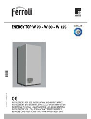
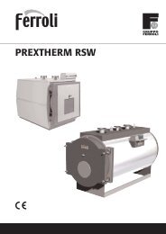
Energy Top Range - Brochure - Ferroli
Energy Top Range - Brochure - Ferroli
Energy Top Range - Brochure - Ferroli
Create successful ePaper yourself
Turn your PDF publications into a flip-book with our unique Google optimized e-Paper software.
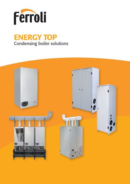
ENERGY TOPCondensing boiler solutions1
ENERGY TOP> > > Heating division> ENERGY TOP RANGEA wide array of flexible solutions both for centralisedresidential application and big commercial plantsThe increasing need for families to be able to manage their central heating systemfreely and independently led to the expansion of independent systems, gainingground over the traditional centralised approach to heating. Independent systemshave been and continue to be preferred by users, mainly due to:- independent management- costs exactly corresponding to own consumption;- less possibility of controversies between residents.Nonetheless, centralised systems, albeit less appreciated by users, have beenrecently reappraised thanks to some undeniable qualities : less overall capacityinstalled; less environmental impact due to the use of just one flue or stack, andseparate installation of the generator in a boiler room.The development of centralised systems with independent billing, using so-calledsubmeter, combine all the advantages of independent and centralised systemsmentioned above. For this reason, the new series of ENERGY TOP modularheat generators together with submeter DADO (not described in this catalogue)represent a modern and complete solution to the latest needs, which require abalance between centralised production of heat and independent and individualmanagement of consumption.Both in the residential and the commercial field, wide output modulation range of<strong>Energy</strong> <strong>Top</strong>, additionally enhanced in modular installation, together with its low hydraulicpressure drop, allows design and carrying out of flexible systems with extremely compactdimensions, fully in line with the latest heating technology design criteria.PRODUCT IN BRIEFPROTECTEDEXTERNALREMOTEMODULARCLIMATICCLASS 5NOX-5 . C-10 . CPossible outdoor installation in apartially sheltered site (EN297 prA6) with minimum temperature-5°C (ENERGY TOP W)Possible outdoor installation withminimum temperature -10°C(ENERGY TOP B/BK)Remote monitoring of boilerfunctions through Openthermremote control (ROMEO)Electronics features built-inmaster-slave cascadeoperation, without additionalcontrollersPossible connection to an optionaloutdoor probe,thus enabling system flowtemperature compensationClass 5 emissions, i.e. the mostsevere and ecological classaccording to European directives(EN 297 and 483)AISI 316 stainless steel casing,highly resistant to atmosphericagents (ENERGY TOP BI/BKI)> DADO(metering cassettes for centralizedheating and domestic hot waterproduction)> ENERGY TOP W(side-by-side)> ENERGY TOP B(side-by-side)> ENERGY TOP B(back-to-back)> ENERGY TOP B 160> ENERGY TOP B 250> ENERGY TOP B 80> ENERGY TOP B 125> ENERGY TOP BK 80> ENERGY TOP BK 125> ENERGY TOP W 80> ENERGY TOP W 1252
ENERGY TOP> > > Heating division> THE HEARTHEATING UNITThe HEART of ENERGY TOP is an innovative heating unitthat ensures the product excellent characteristics in terms ofefficiency and flexible modulation. The new total premixed air-gascombustion unit with variable speed fan, pneumatic gas valve andcylindrical metal fibre burner allows a range of modulation that,depending on the model, can extend from 11 to 100% of ratedoutput, with efficiency exceeding 107%. Heat exchange takesplace in the spiral corrugated pipe exchanger, which features lowpressure drop. Despite the high heat exchange surface, it isparticularly sturdy and compact.The quality of the materials used ensures the exchanger a highlevel of resistance to corrosion and thermal dilations, supportinga max ΔT of 40°C. The very low polluting emissions - NOx andCO - as well as minimising the environmental impact of theseheat generators (class 5 according to EN 297/A5), also let theheat exchanger remaining clean over time, reducing to theminimum maintenance intervention. Ignition is electronic, withflame control by ionisation.The heating units have been designed with two different heatinput ratings: 75 and 116 kW, and based on the total output, thevarious models of ENERGY TOP can house one or two units of 75or 116 kW each, always inside a unique cabinet structure.The models with two heating units are also managed by the sameelectronic controller.100%50%30%22%11%ENERGY TOP 80> MODULATION RANGEENERGY TOP 125ENERGY TOP 160ENERGY TOP 250PREMIX BURNERPremixed air-gas, metal fibre burner,with variable speed fan.EXCHANGERConsisting in a spiral corrugated pipeENERGY TOP Bwith two heating units3
ENERGY TOP> > > Heating division> THE MINDCONTROL UNIT2 32 3164 7KEY1 Display2 Central heating temperature setting3 Domestic hot water temperature setting(with optional storage cylinder)4 Summer/Winter mode5 On/Off6 Reset parameters7 Economy/Comfort mode5Remote timer control connectedInformationReset generatorFaultGenerator offTemperature compensation modeCentral heating modePump ONBurner ONEconomy modeDomestic hot water operationRead parametersDomestic hot water modeThe evolved electronics on ENERGY TOP can perfectly manage applications where multiple heat generators are used in cascading, minimisingthe configuration and commissioning operations.The MASTER/SLAVE function allows operation of a series of cascaded boilers, without requiring an additional control unit. With just a simpleconnection (two wires) between the control boards of the boilers in the cascade, the entire system acts as a single virtual boiler. The safetycircuit reduces boiler lockout and system shutdown, automatically attempting to ignite the module three times in the event of temporaryshutdown (natural gas versions). If the shutdown occurs repeatedly, the system goes into permanent lockout mode, for safety reasons.Control board features a series of input and output signals, both analogue and digital (on/off), in order to control or adjust the operation ofthe single boiler or the entire cascade system also via a remote connection. Below are some examples:FAULT SIGNALActive in case of boiler’s fault messageBURNER ON SIGNALActive when at least one heating unit is onRESET SIGNALUsed to reset “temporary” faultsCombined management of the signals allowsthe operating status of the heat generatorto be checked and set via a remote connection°C/%P10 Volt0-10 VOLT INPUT SIGNALAllows the boiler (or cascade of boilers)to be controlled via a remote connection,in system outlet temperature or outputpercentage mode.ELECTRONIC INSTALLATIONSUPERVISOR4
ENERGY TOP> > > Heating division> THE MINDCONTROL UNIT0-10 Volt input signal, available on the electronics, enables the boilers to be interfaced to any generic external control unit featuring a 0-10Volt output. In this way, the ENERGY TOP series generators can be very easily installed in existing systems with electronic supervisor.Below some examples using the 0-10 Volt signal are shown.> 0-10 V CONTROL: ON “MASTER” MODULE0-10 Volt signalInstallationSUPERVISORZONE 1 ZONE 2 ZONE 3Control based on the centralheating flow temperatureor percentage of equivalentgenerator output, using a unique0-10 Volt signal connectedto the MASTER generator.Information received by theMASTER generator will be used tocontrol the SLAVE ones.> 0-10 V CONTROL: INDIVIDUALLY ON “SLAVE” MODULESInstallationSUPERVISOR0-10 Volt signalZONE 1 ZONE 2 ZONE 3Control based on the systemoutlet temperature or percentageof equivalent generator outputusing individual 0-10 Volt signals.5
ENERGY TOP W> > > Heating division> SPECIFICATIONSRANGE – TECHNICAL DRAWINGSThe ENERGY TOP W series boilers are wall-hung heat generators forinside or outside installation, central heating only, featuring a premixburner, condensing operation with very high efficiency and very lowpolluting emissions. They consequently ensure high energy savingsand are environmentally-friendly (4 star energy rating according toDirective 92/42 EEC, Class 5 emissions according to EN 297/A5).Wall-hung structure with removable jacket split in 3 sections, for easyaccess to the inner components. Possible installation as standardoutdoor in partially protected places, with temperatures untill to-5°C, without using the additional frost protection kit. The cascadedconnection of multiple generators can be carried out using dedicatedcascade flues and hydraulic collective manifold.The appliances are factory configured for operation on natural gas andcan be converted to LPG using the appropriate conversion kit availableupon demand.> THE RANGEENERGY TOP W 80Wall hung model with single heating unit and thermal input from17 to 75 kWENERGY TOP W 125Wall hung model with double heating unit and total thermal inputfrom 25 to 116 kWKEY1 CH flow 1” 1/2 F3 Gas inlet1” M5 Ch return 1” 1/2 FENERGY TOP W A mm80 65125 636
ENERGY TOP W> > > Heating division> SPECIFICATIONSTECHNICAL DATAENERGY TOP W 80 W 125PerformancesHeating thermal input max kW 75 116Heating thermal input min kW 17 25Thermal output max (80-60°C) kW 73,5 113,7Thermal output min (80-60°C) kW 16,7 24,6Thermal output max (50-30°C) kW 79,5 123Thermal output min (50-30°C) kW 18,3 26,9Efficiency Pmax (80-60°C) % 98 98Efficiency Pmin (80-60°C) % 98,5 98,5Efficiency Pmax (50-30°C) % 106 106Efficiency Pmin (50-30°C) % 107,5 107,5Efficiency 30% (30°C) % 109 109<strong>Energy</strong> marking (92/42 ECC) ★★★★ ★★★★Nox emission class (EN 297/A5 Directive) 5 5Gas flow (G 20) max m 3 /h 79,4 12,38Gas flow (G 20) min m 3 /h 1,8 2,65Operating gas pressure (G20) mbar 20 20G31 gas delivery max kg/h 5,87 9,08G31 gas delivery min kg/h 1,33 1,96G31 pressure at burner mbar 37 37Max operating temperature °C 95 95Operating pressure max bar 6 6Operating pressure min bar 0,8 0,8Max exchanger ∆ΔT °C 40 40Water content litres 5 7Electric characteristicsIP protection rating IP X5D X5DPower supply voltage V/Hz 230/50 230/50Electrical absorption (pump excluded) W 95 200Dimensional characteristicsEmpty weight kg 46 51Height mm 900 900Width mm 445 445Depht mm 430 430HydraulicCircuit flow/return connections inches 1” 1/2 1” 1/2Gas connection inches 3/4” 1”Combustion dataChimney loss (with burner on) Pmax-Pmin % 2,2-1,3 1,8-1,3Jacket loss (with burner on) Pmax-Pmin % 0,2-0,2 0,2-0,2Loss at chimney with burner OFF % 0,03 0,02Loss at jacket with burner OFF % 0,4 0,4Flues temperature Pmax-Pmin (80-60°C) °C 65-60 67-60Flues temperature Pmax-Pmin (50-30°C) °C 43-33 45-34Flues flow Pmax-Pmin kg/h 126,2-30,1 195,2-44,3Condensate production Pmax-Pmin kg/h 8,7-2 13,5-3,2CO2 Pmax-Pmin (G20) % 9-8,5 9-8,5CO2 Pmax-Pmin (G31) % 10-9,2 10-9,2CO average mg/kWh 35 35NOx average mg/kWh 29 29Max head at stack pascal 250 3507
ENERGY TOP W> > > Heating division> SPECIFICATIONSWATER CIRCUIT2916The water circuit is simple, rational and allows easy access to theinner components.36 443458127882KEY - 7 Gas inlet 10 Central heating flow outlet 11 Central heating return inlet16 Fan 22 Main burner 29 Flue gas outlet manifold 36 Automatic air vent38 Flow-switch 44 Gas valve 81 Ignition electrode 82 Detection electrode114 Water pressure switch 154 Condensate drain connection 186 Returnsensor 188 Ignition electrode 193 Drain trap 196 Condensate basin278 Double sensor (heating + safety) 345 Exchanger safety thermostat22196The central heating pump is available as a dedicated optional kitcomplete with on-off valves, non-return valves and safety valve. Thelow water pressure drop in the exchanger coil and the use of a centralheating pump with 8 m head ensure high net head in the system.15419311410 11 738186HYDRAULIC KIT FOR SINGLE BOILER,SPEED PUMPcode 042021X0HYDRAULIC KIT FOR SINGLE BOILER,MODULATING PUMPcode 042043X0Hydraulic kit complete with central heating pump,central heating flow and return on-off valves,non-return valve, 6 bar safety valve.> BOILER PRESSURE DROP DIAGRAMSENERGY TOP W 80 ENERGY TOP W 125> PUMP KIT FLOW-RATE / HEAD DIAGRAMcode 042021X0 / WITH 3 SPEED PUMPcode 042043X0 / WITH MODULATING PUMP8
ENERGY TOP W> > > Heating division> SPECIFICATIONSCASCADEA series of water circuit accessories and self-supporting frames is available for the ENERGY TOP W boilers, used to create different cascading layouts.As structure is self-supporting, it does not need to be anchored to the walls, so installation can eventually be made also in the middle of the boiler room.3Acode. 042021X0Hydraulic kit for modular installation, complete with on-off valvesand 3 speed pump1code 042031X0Basic kit self-supporting frame for first boiler of the cascade,complete with support brackets2code 042032X0Self-supporting frame extension kit for individual boiler (afterthe first one in the cascade), complete with support brackets112 223Bcode 042043X0Hydraulic kit for modular installation, complete with on-off valvesand modulating pump3A/B 3A/B 3A/B 3A/B4code 042030X0Hydraulic separator745 6 6 675code 042028X0Basic water manifold for first boiler in the cascade,DN65 (2” 1/2) with safety devices (excluding safety valve) and gasmanifold, DN40 (1” 1/2)6 7code 042029X0code 042033X0Water manifold extension kit for individual boiler (after the first Flange kit, containing: 3 blindone in the cascade), DN65 (2” 1/2) and gas manifold, DN40 flanges, 3 drilled flanges, gaskets(1” 1/2)9
ENERGY TOP W> > > Heating division> SPECIFICATIONSFLUE GAS EVACUATIONVarious solutions are available for the air intake and flue gas evacuation on the ENERGY TOP W wall-hung boilers, for either individual andmodular installation. The low flue gas temperature implies special polypropylene accessories can be used. As regards individual dischargesystem, both 80 mm separate and 80/125 mm coaxial flue gas outlet configurations are available, with comburent air intake either from theroom or the outside. All basic accessories close to boiler’s stack are fitted with test fittings for combustion analysis.> INDIVIDUAL EVACUATION SYSTEM > TECHNICAL DATAcode 041000X090° PPs bend, Ø 80 mm,with flue test pointcode 1KWMA70WPPs vertical connection, Ø80 mm, with flue test pointcode 041007X080/125 coaxial adapter, with fluetest pointENERGY TOP W 80 W 125StackMaximum stack pressure head at Pmax pascal 200 250Maximum length 80/125 m 4 2Maximum separate length meq 20 10As regards the modular installations, flue gas manifolds are available for total output of around 500 kW.If these ducts are used, combustion air intake occurs directly from the boiler room, through the air intake grills included in the kit.8 9 9 9 9 10118code 041026X0Condensate drain trap complete with fasteningbrackets10code 041019X01 mt PPs extension, ø 200 mm MF> POSSIBLE MODULAR CONFIGURATIONSINPUTkWTOT. OUTPUT (kW) MODULES QTY TOP W DIMENSIONSW x D x H80/60°C 50/30°C 1 2 3 4 mmFLUESMANIFOLDDIAMETER75 73,5 79,5 80 - - - 820x450x2240 -116 113,7 123,0 125 - - - 820x450x2240 -150 147,0 159,0 80 80 - - 1325x450x2240191 187,2 202,5 125 80 - - 1325x450x2240225 220,5 238,5 80 80 80 - 1830x450x2240 200 mm232 227,4 246,0 125 125 - - 1325x450x2240266 260,7 282,0 125 80 80 - 1830x450x22409code 041028X0Grey PPs flue gas manifold kit (L=600mm - ø200 mm) for “side-by-side” modular installation,complete with clapet valves, vertical connections,gaskets and bracketsINPUTkW11code 041016X090° PPs bend, ø 200 mm MFTOT. OUTPUT (kW) MODULES QTY TOP W DIMENSIONSW x D x H80/60°C 50/30°C 1 2 3 4 mm300 294,0 318,0 80 80 80 80 2335x450x2240307 300,9 325,5 125 125 80 - 1830x450x2240341 334,2 361,5 125 80 80 80 2335x450x2240348 341,1 369,0 125 125 125 - 1830x450x2240382 374,4 405,0 125 125 80 80 2335x450x2240423 414,6 448,5 125 125 125 80 2335x450x2240464 454,8 492,0 125 125 125 125 2335x450x2240FLUESMANIFOLDDIAMETER200 mm10
ENERGY TOP W> > > Heating division> SPECIFICATIONSSETTING AND CONTROLThe ENERGY TOP W series boilers boast an evolved electronics that can manage as standard up to two direct heating zones or an eventual storagecylinder with one direct zone, without requiring additional electronic controllers.PS: Diagrams are for mere example only and need to be verified according to the specific installation.> MIXED CIRCUIT WITH PRIORITY TO THE STORAGE TANKLegionella disinfection signalRecirculationtimerEach boiler or cascade of boilerscan be connected to an outdoortemperature probe for flowtemperature compensationoperation. MASTER-SLAVEinterconnection between the boilerspermits multiple cascadeconfigurations without requiringadditional control boards.> MIXED CIRCUIT WITH PRIORITY OR SIMULTANEOUS OPERATION OF THE STORAGE TANKLegionella disinfection signalRecirculationtimerThe Legionella protection function,after a programmable time interval,ensures the temperature inside thestorage cylinder remains at 65°Cfor 15 minutes. When Legionellaprotection is active, the boiler’selectronics sends an output signal(voltage-free contact) that can beused to control a recirculating pump.This ensures the entire water contentin the circuit is protected.In the case of combined systems (without diverting valve) domestic hot water storage cylinder can be heated simultaneously with the centralheating or as a priority function depending on the characteristics of the system.11
ENERGY TOP W> > > Heating division> SPECIFICATIONSSETTING AND CONTROL> CENTRAL HEATING ONLY DIAGRAM WITH DIRECT OUTLETZONE 1 ZONE 2It is possible to manage two directzones, without adding additionalcontrollers.> MIXED CIRCUIT WITH STORAGE TANK AND DIRECT OR MIXED HEATING ZONESZONE 1 ZONE 2 ZONE 3Legionella disinfection signalRecirculationtimerMore complex system diagrams, onthe other hand, can be managedby using zone controllers thatcan interface directly with theboiler’s electronics, thus achievingmaximum efficiency by adaptingthe operation of the boilersaccording to actual system loadrequirements. In this case too,the operation of the domestic hotwater circuit can be managed withpriority or together with the centralheating circuits.12
ENERGY TOP W> > > Heating division> SPECIFICATIONSACCESSORIES LIST FOR MODULAR SYSTEMSThe table herebelow lists thecomponents that can be used to createcascading configurations.They are sub-divided into “basic”accessories - required to create thebasic structure for water circuit andflue gas evacuation - and “additional”accessories that may be used toconfigure and complete the systemdepending on the type of installationcarried out (e.g.: hydraulic separator,zoning controller, flues extensions etc.).> CONFIGURATION SAMPLESPS: TO BE CONSIDERED MERELY ASAN EXAMPLE AND TO BE VERIFIEDACCORDING TO THE SPECIFIC PLANTHEATINPUTkWHEATOUTPUT80/60°CkWMODULESENERGY TOP Wcondensate drain trap for ø200 mm flue gas manifoldø 200 mm flue gas manifoldHydraulic kit completewith on/off ormodulating pump*Water manifold kit for first boilerin the cascade. Includes safetydevices (excluded safety valve)Self-supporting frame forfirst boiler in the cascadeWater manifold extension kitfor each additional boiler inthe cascadeFrame extension kit foreach additional boiler in thecascadeFlange kitWater circuit separatorAdditional system flowprobeZoning controller (max 2mixed and a direct one)Outdoor probeAdditional probe forhandling an eventual DHWtank (5 mts)041026X0 041028X0 042021X0 042028X0 042031X0 042029X0 042032X0 042033X0 042030X0 043005X0 013013X0 013018X0 043005X0 041019X0 041016X0042043X075 75 80 - - - - - 1 1 1 - - 1 1 1 1 1 1 - -116 116 125 - - - - - 1 1 1 - - 1 1 1 1 1 1 - -150 147 80 80 - - 1 2 2 1 1 1 1 1 1 1 1 1 1 x x191 187,2 125 80 - - 1 2 2 1 1 1 1 1 1 1 1 1 1 x x225 220,5 80 80 80 - 1 3 3 1 1 2 2 1 1 1 1 1 1 x x232 227,4 125 125 - - 1 2 2 1 1 1 1 1 1 1 1 1 1 x x266 260,7 125 80 80 - 1 3 3 1 1 2 2 1 1 1 1 1 1 x x300 294 80 80 80 80 1 4 4 1 1 3 3 1 1 1 1 1 1 x x307 300,9 125 125 80 - 1 3 3 1 1 2 2 1 1 1 1 1 1 x x341 334,2 125 80 80 80 1 4 4 1 1 3 3 1 1 1 1 1 1 x x348 341,1 125 125 125 - 1 3 3 1 1 2 2 1 1 1 1 1 1 x x382 374,4 125 125 80 80 1 4 4 1 1 3 3 1 1 1 1 1 1 x x423 414,6 125 125 125 80 1 4 4 1 1 3 3 1 1 1 1 1 1 x x464 454,8 125 125 125 125 1 4 4 1 1 3 3 1 1 1 1 1 1 x xMODULES BASIC ACCESSORIES EVENTUAL ADDITIONAL ACCESSORIES1 mt MF flue gas manifoldextension, ø 200 mm90° MF bend, ø 200 mmPS: “-” not possible; “x” qty according to the flues required installationPS2: * use the same kit type on alla modules: only on-off pump (042021X0) or only modulating one (042043X0)13
ENERGY TOP B/BK> > > Heating division> SPECIFICATIONSRANGE – TECHNICAL DRAWINGSENERGY TOP B/BK vertical modules are floor-standing heat generatorsfor indoor or outdoor installation, central heating only, featuring a premixburner, condensing operation with very high efficiency and very lowpolluting emissions. They consequently ensure high energy savings and areenvironmentally friendly (4 star energy rating according to Directive92/42 EEC, emission Class 5 as per EN 297/A5). The insulated paintedsteel cabinet, with reversible door (left-right), can be installed as standardoutdoor in completely open places with minumum temperature -10°C,without using additional frost protection kits. Each module is complete withinsulated central heating flow and return manifolds - DN 100 - and gasmanifold - DN 65.The cascaded connection of more generators can be performed usingdedicated flue gas and hydraulic accessories. The appliances are factoryconfigured for operation on natural gas and can be converted to LPG usingan appropriate conversion kit. The range features four sizes, two with singleheating unit and two with double heating unit.only mod.BKREVERSIBLECONNECTIONRIGHT/LEFT FORFREE-STANDINGWATER TANKMOD. B: HEATING ONLYMOD. BK: HEATING OPERATION WITH CONNECTIONTO FREE-STANDING WATER TANKS.> THE RANGEENERGY TOP B/BK 80Vertical module, single furnace with heat input from 17 to 75 kWENERGY TOP B/BK 125Vertical module, single furnace with heat input from 25 to 116 kWENERGY TOP B 160Vertical module, double furnace with heat input from 17 to 150 kWENERGY TOP B 250Vertical module, double furnace with heat input from 25 to 232 kWKEYa1 Central heating flow (DN 100)a2 Central heating return (DN 100)a3 Condensate drain ø 40 mma5 Gas inlet (DN 65)(only for mod. BK)a6 Flow to tank’s coil 1” 1/2a7 Return from tank’s coil 1” 1/2ENERGY TOP Bmod. 160-250ENERGY TOP B/BKmod. 80-125ENERGY TOP BKENERGY TOP B14
ENERGY TOP B/BK> > > Heating division> SPECIFICATIONSTECHNICAL DATAENERGY TOP B/BK 80 B/BK 125 B 160 B 250PerformancesHeating thermal input max kW 75 116 150 232Heating thermal input min kW 17 25 17 25Thermal output max (80-60°C) kW 73,5 113,7 147 227,4Thermal output max (80-60°C) kW 16,7 24,6 16,7 24,6Thermal output max (50-30°C) kW 79,5 123 159 246Thermal output max (50-30°C) kW 18,3 26,9 18,3 26,9Efficiency Pmax (80-60°C) % 98 98 98 98Efficiency Pmin (80-60°C) % 98,5 98,5 98,5 98,5Efficiency Pmax (50-30°C) % 106 106 106 106Efficiency Pmin (50-30°C) % 107,5 107,5 107,5 107,5Efficiency 30% (30°C) % 109 109 109 109<strong>Energy</strong> marking (92/42ECC) ★★★★ ★★★★ ★★★★ ★★★★Nox emission class (EN 297/A5 Directive) 5 5 5 5Operating pressure max-min bar 6-0,8 6-0,8 6-0,8 6-0,8Max operating temperature °C 95 95 95 95Max exchanger ∆t °C 40 40 40 40Water content litres 13 15 26 30Electric characteristicsIP protection rating IP X5D X5D X5D X5DPower supply voltage V/Hz 230/50 230/50 230/50 230/50Electrical absorption W 285 390 570 780Dimensional characteristicsEmpty weight kg 110 115 190 210Height mm 1700 1700 1700 1700Width mm 500 500 1000 1000Depht mm 450 450 450 450ConnectionsSystem flow/return connection inches DN 100 DN 100 DN 100 DN 100Gas connection inches DN 65 DN 65 DN 65 DN 65Combustion data (for each furnace)Appliance type (EN/TR 1749) B23 B23 B23 B23Chimney loss with burner ON Pmax-Pmin % 2,2-1,3 1,8-1,3 2,2-1,3 1,8-1,3Jacket loss with burner ON Pmax-Pmin % 0,2-0,2 0,2-0,2 0,2-0,2 0,2-0,2Loss at chimney with burner OFF % 0,03 0,02 0,03 0,02Jacket loss with burner OFF % 0,4 0,4 0,4 0,4Flues temperature Pmax-Pmin (80-60°C) °C 65-60 67-60 65-60 67-60Flues temperature Pmax-Pmin (50-30°C) °C 43-33 45-34 43-33 45-34Flues flow Pmax-Pmin kg/h 126,2-30,1 195,2-44,3 126,2-30,1 195,2-44,3Condensate flow rate Pmax-Pmin kg/h 8,7-2 13,5-3,2 8,7-2 13,5-3,2CO2 Pmax-Pmin (G20) % 9-8,5 9-8,5 9-8,5 9-8,5CO2 Pmax-Pmin (G31) % 10-9,2 10-9,2 10-9,2 10-9,2CO average mg/kWh 35 35 35 35NOx average mg/kWh 29 29 29 2915
ENERGY TOP B/BK> > > Heating division> SPECIFICATIONSWATER CIRCUITThe water circuit in vertical modules, compared to the wall-hung versions, is already included as standard with all the components required forcomplete and correct installation in the boiler room. Each furnace is connected to the central heating flow and return hydraulic manifolds via3-way on-off valves vented to the atmosphere and is equipped with fixed speed pump.ENERGY TOP B mod. 80 - 125 ENERGY TOP BK mod. 80 - 12536162152929163616215291914422036 4434581278191114442203453458281278812788222821961141541963815411419338186196381861861432141933217925232193209210179252253253179252142531010101015410777771111111111KEY7 Gas inlet 10 System delivery 11 System return 14 Safety valve 16 Fan 22 Burner 29 Fume outlet manifold 32 Heating circulating pump 36 Automatic air vent 38 Flowswitch44 Gas valve 81 Ignition electrode 82 Detection electrode 114 Water pressure switch 154 Condensate outlet pipe 179 Non-return valve 193 Trap 196 Condensate tray 209 Flowto tank’s coil (mod. BK) 210 Return from tank’s coil (mod. BK) 252 3-way drain and shut-off cock 253 Shut-off cock 278 Double sensor (Safety + Heating) B DHW tank (notsupplied) I Safety devices (not supplied) S tank’s probe (not supplied)ENERGY TOP B mod. 160 - 25010107710711111116
ENERGY TOP B/BK> > > Heating division> SPECIFICATIONSFLUE GAS EVACUATIONVarious solutions are available for the air intake and flue gas outlet on the ENERGY TOP B/BK vertical modules, for installation as an individualboiler or as a cascade system. The low flue gas temperature means special polypropylene accessories can be used.As regards flue gas evacuation system independent for each generator, it can occur through 80 mm appropriate optional accessories, withcomburent air intake from the boiler room (type B23).> EVACUATION THROUGH INDIVIDUAL TERMINAL PIPE ø 80 mmEach heating unit, even when connected in cascade, can be connected directly at the 80 mm diameter flue gas outlet, using a special terminalkit complete with pipe, wind-protection grill and gasket. One kit must be used for each flue gas outlet (each furnace).code 041013X0> TECHNICAL DATAENERGY TOP B/BK 80 B/BK 125 B 160 B 250For individual flue gas outletMaximum stack pressure head at Pmax pascal 200 250 200 250Maximum flues length meq 20 10 20 10Sample with individual pipeevacuation systemcode 041013X0Terminal pipe with gasket-individual pipe system ∅∅ 80 mm> COLLECTIVE FLUES MANIFOLDDifferent types of flues manifolds are available, depending on cascading layout chosen, i.e. “side-by-side” or “back-to-back” installation.The diameters of the manifolds depend on the total output of the series of modules.Flues evacuation sample with back-to-back installationback to backFlues evacuation sample with side-by-side installationside by side17
ENERGY TOP B/BK> > > Heating division> SPECIFICATIONSFLUE GAS EVACUATION> EXAMPLE OF “SIDE-BY-SIDE” INSTALLATION The table shows some “side-by-side” cascading combinations and the correspondingmaximum overall dimensions. The corresponding diameter of the flue gas outlet manifold is also shown for each combination.HEAT INPUTkWHEAT OUTPUT80/60°CkWN°MODULES> USING COLLECTIVE FLUES MANIFOLDA wide range of accessories is available to completethe configuration of the cascade system.“SIDE BY SIDE” MODULES LAYOUT CASCADE DIMENSIONS mm FLUE GASMANIFOLD DIAMETER1 2 3 4 5 WIDTH DEPTHmm150 147 1 160 - - - - 1000200191 187,2 2 80 125 - - - 1000 200232 227,4 1 250 - - - - 1000 200266 260,7 2 125 160 - - - 1500 200307 300,9 2 80 250 - - - 1500 200348 341,1 2 125 250 - - - 1500 200382 374,4 2 160 250 - - - 2000 200416 407,7 3 125 160 160 - - 2500 200464 454,8 2 250 250 - - - 2000 200498 488,1 3 125 160 250 - - 2500 300539 528,3 3 80 250 250 - - 2500 300580 568,5 3 125 250 250 - - 2500 450300614 601,8 3 160 250 250 - - 3000 300696 682,2 3 250 250 250 - - 3000 300730 715,5 4 125 160 250 250 - 3500 300771 755,7 4 80 250 250 250 - 3500 300812 795,9 4 125 250 250 250 - 3500 300846 829,2 4 160 250 250 250 - 4000 300928 909,6 4 250 250 250 250 - 4000 3001003 983,1 5 80 250 250 250 250 4500 3001044 1023,3 5 125 250 250 250 250 4500 3001078 1056,6 5 160 250 250 250 250 5000 3001160 1137 5 250 250 250 250 250 5000 3002 1 1 1561code 041028X0 (ø 200 mm)code 041029X0 (ø 300 mm)Flue gas manifold kit, grey PPs (L=600mm) for “side-byside”cascading configurations complete with curve, clapetvalves, vertical connection, gaskets and brackets2code 041026X0 (ø 200 mm)code 041027X0 (ø 300 mm)Condensate drain trap kit for flue gas manifolds completewith fastening brackets.PS. Use one for each cascade system3code 0M600MX0Cabinet complete with hydraulic separatorand safety devices (excluding safety valve)4code 042027X0Flange kit, containing: 3 blind flanges, 3 drilledflanges, gasketsPS. To be used on individual modules or one for eachcascade system445code 041019X0 (ø 200 mm)code 041036X0 (ø 300 mm)1m MF manifold extension pipe, PPs6code 041016X0 (ø 200 mm)code 041035X0 (ø 300 mm)MF 90° bend, PPs18
ENERGY TOP B/BK> > > Heating division> SPECIFICATIONSFLUE GAS EVACUATION> EXAMPLE OF “BACK-TO-BACK” CONFIGURATION The table shows some “back-to-back” cascading combinations and the relative maximumoverall dimensions. The corresponding diameter of the flue gas outlet manifold is also shown for each combination.HEATINPUTkWHEATOUTPUT80/60°CkWNR.MODULES191 187,2 2266 260,7 2307 300,9 2348 341,1 2382374,4 2416 407,7 3464 454,8 2498 488,1 3539 528,3 3580 568,5 3614 601,8 3696 682,2 3730 715,5 4771 755,7 4812 795,9 4846 829,2 4928 909,6 41003 983,1 51044 1023,3 51078 1056,6 51160 1137 51LAYOUT OF “BACK-TO-BACK”MODULES1 3 52 4 680 - -125 - -125 - -160 - -80 - -250 - -125 - -250 - -160 - -250 - -160 125 -160 - -250 - -250 - -160 125 -250 - -250 80 -250 - -250 125 -250 - -160 250 -250 - -250 250 -250 - -160 125 -250 250 -250 80 -250 250 -250 125 -250 250 -160 250 -250 250 -250 250 -250 250 -250 250 80250 250 -250 250 125250 250 -250 250 160250 250 -250 250 250250 250 -CASCADE DIMENSIONSmmWIDTH500DEPTHFLUE GASMANIFOLDDIAMETERmm2001000 2001000 2001000 2001000 2001500 2001000 2001500 3001500 2001500 3002000 900 3002000 3002000 3002000 3002000 3002000 3002000 3002500 3002500 3003000 3003000 30023code 041019X0 (ø 200 mm)code 041036X0 (ø 300 mm)1m MF manifold extension pipe, PPs5code 041030X0 (ø 200 mm)code 041031X0 (ø 300 mm)Flue gas manifold kit, grey PPs (L=600mm),double connection for “back-to-back” cascadingconfigurations, complete with bends, clapet valves,vertical connections, gaskets and bracketsPS. To be used per each pair of fluesoutlets (each pair of furnace) installed inback-to-back layout45564code 041016X0 (ø 200 mm)code 041035X0 (ø 300 mm)MF 90° bend, PPs6code 041026X0 (ø 200 mm)code 041027X0 (ø 300 mm)Condensate drain trap kit for flue gasmanifolds complete with fasteningbracketsPS. Use one for each cascade system7code 0M600MX0Cabinet complete with hydraulicseparator and safety devices (excludingsafety valve)TOP VIEWcode 042026X0code 042027X01code 042026X0Flange kit for cascading configurationwith “back-to-back” boilers2code 042027X0Flange kit, containing: 3 blind flanges, 3drilled flanges, gaskets119
ENERGY TOP B/BK> > > Heating division> SPECIFICATIONSSETTING AND CONTROLThe ENERGY TOP B/BK modules, both in individual and multiple configurations, can manage as standard up to two direct heating zones or aneventual storage cylinder with one direct zone, without requiring additional electronic controllers.> MIXED CIRCUIT WITH PRIORITY TO THE STORAGE TANKLegionella disinfection signalRecirculationtimerMaster-Slave interconnectionbetween the boilers permitsmultiple cascade configurationswithout requiring additionalcontrol boards.The central heating and domestichot water circuits can be managedsimultaneously or with priority tothe domestic hot water.> MIXED CIRCUIT WITH PRIORITY OR SIMULTANEOUS OPERATION OF THE STORAGE TANKLegionella disinfection signalRecirculationtimerThe Legionella protection function,after a programmable time interval,ensures the temperature inside thestorage cylinder remains at 65°Cfor 15 minutes. When Legionellaprotection is active, the boiler’selectronics sends an output signal(voltage-free contact) that canbe used to control a recirculatingpump. This ensures the entire watercontent in the circuit is protected.20
ENERGY TOP B/BK> > > Heating division> SPECIFICATIONSSETTING AND CONTROL> CENTRAL HEATING ONLY DIAGRAM WITH DIRECT OUTLETZONE 1 ZONE 2It is possible to manage two directzones, without adding additionalcontrollers.> MIXED CIRCUIT WITH STORAGE TANK AND DIRECT OR MIXED HEATING ZONESZONE 1 ZONE 2 ZONE 3Legionella disinfection signalRecirculationtimerMore complex system diagrams, onthe other hand, can be managedby using zone controllers thatcan interface directly with theboiler’s electronics, thus achievingmaximum efficiency by adapting theoperation of the boilers accordingto actual system load requirements.In this case too, the operation of thedomestic hot water circuit can bemanaged with priority or togetherwith the central heating circuits.21
ENERGY TOP B/BK> > > Heating division> CONFIGURATIONSACCESSORIES FOR “SIDE-BY-SIDE” MODULAR INSTALLATIONThe table lists the components that can be used to create cascading configurations and the correspondingquantity. They are sub-divided into “basic accessories” - required to create the basic structure for water circuitand flue gas evacuation - and “eventual additional accessories” that may be eventually used to configure andcomplete the system depending on the type of installation carried out (e.g.: need or not of hydraulic separator,zoning controller, flues extensions etc.).> CONFIGURATION SAMPLESPS: TO BE CONSIDERED MERELY AS ANEXAMPLE AND TO BE VERIFIED ACCORDINGTO THE SPECIFIC PLANTFlange kitCondensate trap syphon forø 200 mm flue gas manifoldsCondensate trap syphon forø 300 mm flue gas manifoldsø 200 mm flue gas manifoldø 300 mm flue gas manifoldAdditional system flow probeCabinet including water circuitseparator and safety devices(excluded safety valve)Zoning controller (max 2 mixedcircuits and a direct one)Outdoor probeAdditional probe for handling of aneventual DHW tank (5 mts long)PPs MF manifold extension,ø 200 mm, 1 mt longPPs MF manifold extension,ø 300 mm, 1 mt long90° MF PPs bend, ø 200 mm90° MF PPs bend, ø 300 mmHEATINPUTkWHEATOUTPUT80/60°CkWMODULESENERGY TOP B/BK042027X0 041026X0 041027X0 041028X0 041029X0 043005X0 0M600MX0 013013X0 013018X0 043005X0 041019X0 041036X0 041016X0 041035X0150 147 160 - - - - 1 1 - 2 - 1 1 1 1 1 X - X -191 187,2 80 125 - - - 1 1 - 2 - 1 1 1 1 1 X - X -232 227,4 250 - - - - 1 1 - 2 - 1 1 1 1 1 X - X -266 260,7 125 160 - - - 1 1 - 3 - 1 1 1 1 1 X - X -307 300,9 80 250 - - - 1 1 - 3 - 1 1 1 1 1 X - X -348 341,1 125 250 - - - 1 1 - 3 - 1 1 1 1 1 X - X -382 374,4 160 250 - - - 1 1 - 4 - 1 1 1 1 1 X - X -416 407,7 125 160 160 - - 1 1 - 5 - 1 1 1 1 1 X - X -464 454,8 250 250 - - - 1 1 - 4 - 1 1 1 1 1 X - X -498 488,1 125 160 250 - - 1 - 1 - 5 1 1 1 1 1 - X - X539 528,3 80 250 250 - - 1 - 1 - 5 1 1 1 1 1 - X - X580 568,5 125 250 250 - - 1 - 1 - 5 1 1 1 1 1 - X - X614 601,8 160 250 250 - - 1 - 1 - 6 1 1 1 1 1 - X - X696 682,2 250 250 250 - - 1 - 1 - 6 1 1 1 1 1 - X - X730 715,5 125 160 250 250 - 1 - 1 - 7 1 1 1 1 1 - X - X771 755,7 80 250 250 250 - 1 - 1 - 7 1 1 1 1 1 - X - X812 795,9 125 250 250 250 - 1 - 1 - 7 1 1 1 1 1 - X - X846 829,2 160 250 250 250 - 1 - 1 - 8 1 1 1 1 1 - X - X928 909,6 250 250 250 250 - 1 - 1 - 8 1 1 1 1 1 - X - X1003 983,1 80 250 250 250 250 1 - 1 - 9 1 1 1 1 1 - X - X1044 1023,3 125 250 250 250 250 1 - 1 - 9 1 1 1 1 1 - X - X1078 1056,6 160 250 250 250 250 1 - 1 - 10 1 1 1 1 1 - X - X1160 1137 250 250 250 250 250 1 - 1 - 10 1 1 1 1 1 - X - XMODULES BASIC ACCESSORIES EVENTUAL ADDITIONAL ACCESSORIESPS: “-” not possible; “x” qty according to the flues required installation22
ENERGY TOP B/BK> > > Heating division> CONFIGURATIONSACCESSORIES FOR “BACK-TO-BACK” MODULAR INSTALLATION> CONFIGURATION SAMPLESPS: TO BE CONSIDERED MERELY ASAN EXAMPLE AND TO BE VERIFIEDACCORDINGTO THE SPECIFIC PLANTFlange kitFlange kit for “back-to-back”modular installationCondensate trap syphon forø 200 mm flue gas manifoldsCondensate trap syphon forø 300 mm flue gas manifoldsGrey PPS flue gas manifold with doubleconnection for “back-to-back” modularinstallation, ø 200 mm, 600 mm longGrey PPS flue gas manifold with doubleconnection for “back-to-back” modularinstallation, ø 300 mm, 600 mm longAdditional system flow probeCabinet including water circuitseparator and safety devices(excluded safety valve)Zoning controller (max 2 mixedcircuits and a direct one)Outdoor probeAdditional probe for handling of aneventual DHW tank (5 mts long)PPs MF manifold extension,ø 200 mm, 1 mt longPPs MF manifold extension,ø 300 mm, 1 mt long90° MF PPs bend, ø 200 mm90° MF PPs bend, ø 300 mmHEATINPUTkWHEATOUTPUT80/60°CkWMODULESENERGY TOPB/BK042027X0 042026X0 041026X0 041027X0 041030X0 041031X0 043005X0 0M600MX0 013013X0 013018X0 043005X0 041019X0 041036X0 041016X0 041035X0191 187,2266 260,7307 300,9348 341,1382 374,4416 407,780 - -125 - -125 - -160 - -80 - -250 - -125 - -250 - -160 - -250 - -160 125 -160 - -1 1 1 - 1 - 1 1 1 1 1 X - X -1 1 1 - 2 - 1 1 1 1 1 X - X -1 1 1 - 2 - 1 1 1 1 1 X - X -1 1 1 - 2 - 1 1 1 1 1 X - X -1 1 1 - 2 - 1 1 1 1 1 X - X -1 1 1 - 2 - 1 1 1 1 1 X - X -464 454,8 250 - - 1 1 1 - 2 - 1 1 1 1 1 X - X -250 - -498 488,1 160 125 - 1 1 - 1 - 3 1 1 1 1 1 - X - X250 - -250 80 -539 528,31 1 - 1 - 3 1 1 1 1 1 - X - X250 - -580 568,5 250 125 - 1 1 - 1 - 3 1 1 1 1 1 - X - X250 - -160 250 -614 601,81 1 - 1 - 4 1 1 1 1 1 - X - X250 - -696 682,2 250 250 - 250 - -1 1 - 1 - 4 1 1 1 1 1 - X - X730 715,5160 125 -250 250 -1 1 - 1 - 4 1 1 1 1 1 - X - X771 755,7250 80 -250 250 -1 1 - 1 - 4 1 1 1 1 1 - X - X812 795,9250 125 -250 250 -1 1 - 1 - 4 1 1 1 1 1 - X - X846 829,2 160 250 - 1 1 - 1 - 4 1 1 1 1 1 - X - X250 250 -928 909,6 250 250 - 1 1 - 1 - 4 1 1 1 1 1 - X - X250 250 -1003 983,1 250 250 80 1 1 - 1 - 5 1 1 1 1 1 - X - X250 250 -1044 1023,3 250 250 125 1 1 - 1 - 5 1 1 1 1 1 - X - X250 250 -1078 1056,6 250 250 160 1 1 - 1 - 6 1 1 1 1 1 - X - X250 250 -250 250 2501160 11371 1 - 1 - 6 1 1 1 1 1 - X - X250 250 -MODULES BASIC ACCESSORIES EVENTUAL ADDITIONAL ACCESSORIESPS: “-” not possible; “x” qty according to the flues required installation23
10.2011FERROLI around the WorldITALY www.ferroli.itSPAIN www.ferroli.esFRANCE www.ferroli.frUNITED KINGDOM www.ferroli.co.ukNETHERLANDS www.ferroli.nlGERMANY www.ferroli.deTURKEY www.ferroli.com.trROMANIA www.ferroli.roPOLAND www.ferroli.com.plRUSSIA www.ferroli.ruUKRAINE www.ferroli.uaBELARUS www.ferroli.byCHINA www.ferroli.com.cnBALKANS www.ferroli.hrIRAN www.ferroli.irVIETNAM www.ferroli.com.vn<strong>Ferroli</strong> spa ¬ 37047 San Bonifacio (Verona) Italy ¬ Via Ritonda 78/Atel. +39.045.6139411 ¬ fax +39.045.6100233www.ferroli.it ¬ e-mail: export@ferroli.itWARNING FOR TRADERS: As part of its efforts to constantlyimprove its range of products, with the aim of increasingthe level of Customer satisfaction, the Company stressesthat the appearance, dimensions, technical data and accessoriesmay be subject to variation. Consequently, ensurethat the Customer is provided with updated documents.


