Radio Thermostat Clock Installation & User Instructions - Ferroli
Radio Thermostat Clock Installation & User Instructions - Ferroli
Radio Thermostat Clock Installation & User Instructions - Ferroli
Create successful ePaper yourself
Turn your PDF publications into a flip-book with our unique Google optimized e-Paper software.
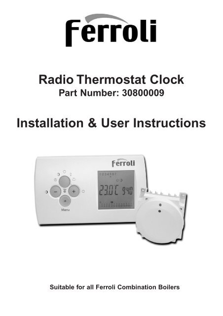
<strong>Radio</strong> <strong>Thermostat</strong> <strong>Clock</strong>Part Number: 30800009<strong>Installation</strong> & <strong>User</strong> <strong>Instructions</strong>Suitable for all <strong>Ferroli</strong> Combination Boilers
Short DescriptionShort description <strong>Radio</strong> <strong>Thermostat</strong> <strong>Clock</strong> - TransmitterThe <strong>Radio</strong> <strong>Thermostat</strong> <strong>Clock</strong> is a 7 day radio frequency (RF) wirelessthermostat/ timer which communicates with a special receiver designedto replace the universal digital timer fitted to most of <strong>Ferroli</strong>’s combinationboilers.The <strong>Radio</strong> <strong>Thermostat</strong> <strong>Clock</strong> is battery powered and can be sitedwherever conventional room thermostats would normally be sited.In combination with the <strong>Radio</strong> <strong>Thermostat</strong> <strong>Clock</strong> receiver, the <strong>Radio</strong><strong>Thermostat</strong> <strong>Clock</strong> transmitter creates a room thermostat clock of highlyadvanced technology. The device is wireless and controls the heatingboiler via radio, providing comfortable room temperatures.Safety <strong>Instructions</strong>Safety <strong>Instructions</strong>Both receiver and transmitter should be fitted by a competent person.It is imperative to observe the generally applicable safety measures,such as: Before starting any work on fitting the receiver, switch off powersupply and secure against switching on.Do not use any metallic and sharp pointed objects for the operation ofthe keys.For technical data, see label on the unit or data sheet.3
Optima 01 RangeUniversalDigital<strong>Clock</strong>5 3 2 14 3 2 1<strong>Radio</strong><strong>Thermostat</strong><strong>Clock</strong> ReceiverStep 1Step 2Step 3Remove clock from control panel.Swap wiring as shown. Make sure Live is connected to terminal 1 (wirecolour is not conclusive of polarity)Fit receiver into control panel.Note. If the <strong>Radio</strong> thermostat clock is going to replace the existing room thermostatthis must be linked out on the room thermostat terminal block located in the electricalcompartment on the underside of the boiler.Domina, Modena and Falcon (MF02)Note. If the <strong>Radio</strong> thermostat clock is going to replace the existing room thermostatthis must be linked out on the room thermostat terminal block.UniversalDigital<strong>Clock</strong>5 3 2 14 3 2 1<strong>Radio</strong><strong>Thermostat</strong><strong>Clock</strong> ReceiverStep 1Step 2Step 3Remove clock from control panel.Swap wiring as shown. Make sure Live is connected to terminal 1 (wirecolour is not conclusive of polarity)Fit receiver into control panel.5
Domina, Modena and FalconNote. If the <strong>Radio</strong> thermostat clock is going to replace the existing room thermostatthis must be linked out on the room thermostat terminal block.UniversalDigital<strong>Clock</strong>5 3 2 14 3 2 1<strong>Radio</strong><strong>Thermostat</strong><strong>Clock</strong> ReceiverStep 1Step 2Step 3Remove clock from control panel.Swap wiring as shown. Make sure Live is connected to terminal 1 (wirecolour is not conclusive of polarity)Fit receiver into control panel.Domicompact RangeUniversalDigital<strong>Clock</strong>5 3 2 1Step 1Step 2Step 34 3 2 1<strong>Radio</strong><strong>Thermostat</strong><strong>Clock</strong> ReceiverRemove clock from control panel.Swap wiring as shown. Make sure Live is connected toterminal 1 (wire colour is not conclusive of polarity)Fit receiver into control panel.6Note. If the <strong>Radio</strong> thermostat clock is going to replace the existing room thermostatthis must be linked out on the room thermostat terminal block.
Optimax 25CNote. If the <strong>Radio</strong> thermostat clock is going to replace the existing room thermostatthis must be linked out on the room thermostat terminal block.UniversalDigital<strong>Clock</strong>5 3 2 14 3 2 1<strong>Radio</strong><strong>Thermostat</strong><strong>Clock</strong> ReceiverStep 1Step 2Step 3Remove clock from control panel.Swap wiring as shown.Fit receiver into control panel.Maxima 35CStep 1Step 2Step 3Step 4Step 5Step 6Remove the boiler front cover andlower the control box.Remove the terminal block cover.Cut off connect block bare back wiresapprox. 7mm and connect brown toterminal 1 and blue to terminal 3 onthe outlet side of the block.Connect brown and blue onto receiverterminals 1 and 2. Make sure live isconnected to terminal 1.Connect the two grey wires to terminal3 and 4 on the receiver. On the mainboiler terminal block remove link wirefrom terminals 4 and 5 and connectthe two grey wires.Place receiver on back of terminal block cover and mark two diagonallyopposed fixing holes, with the cover removed drill two 2.2mm holes.Mount the receiver using the shortest two screws supplied with the radiothermostat.7
Optimax HE RangeStep 1 Remove boiler outer case and lower control box.Step 2 Remove control box cover.Step 3 Connect brown and blue JST plug onto PCB terminal block X2.Step 4Step 5Step 6Connect brown and blue onto receiver terminals 1 and 2. Makesure live is connected to terminal 1. (the wire colour is notconclusive of polarity).Connect the two grey wires to terminal 3 and 4 on the receiver. Onthe main boiler terminal block remove link wire from terminals 5and 6 and connect the two grey wires.Place receiver on back of terminal block cover and mark twodiagonally opposed fixing holes, with the cover removed drill two2.2mm holes. Mount the receiver using the shortest two screwssupplied with the radio thermostat.8
<strong>Installation</strong>ATTENTION!1<strong>Radio</strong> link installation1. Install transmitter and select continuous radio operationsystem mode. (See page 17)2LEDButton2. Press receiver button and hold down for 2 seconds. TheLED flashes twice. Then release the button. The LED remainson between 1 and 10 seconds. When a correct link betweenthe transmitter and receiver has been established the LEDgoes off. Subsequent RF transmissions are indicated visuallyby a momentary flash of the LED.3. Move transmitter to required location and observe LED tomonitor reception. If no reception and appropriate locationmust be found.4. Stop continuous radio operation.Note: If no reception is possible it has to be checked whether any metalliccupboards or other metallic obstacles may interfere.Emergency running modeIf no valid radio signal is received from the receiver for more than 1 hour, emergency runningmode is activated. ED value 12.8 minutes, switch-on time 30%. See page 16.Location9
80.10.1144.7/07/01


