U.S. Traffic 170E-ATC - Peek Traffic
U.S. Traffic 170E-ATC - Peek Traffic
U.S. Traffic 170E-ATC - Peek Traffic
- No tags were found...

You also want an ePaper? Increase the reach of your titles
YUMPU automatically turns print PDFs into web optimized ePapers that Google loves.
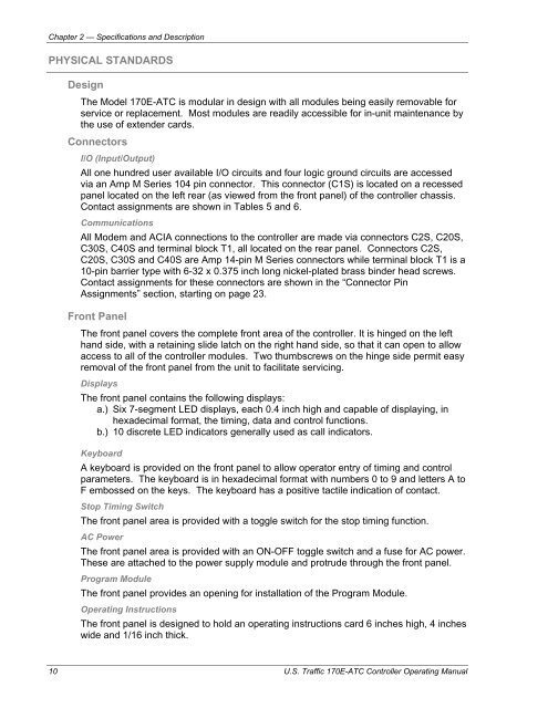
Chapter 2 — Specifications and DescriptionPHYSICAL STANDARDSDesignThe Model <strong>170E</strong>-<strong>ATC</strong> is modular in design with all modules being easily removable forservice or replacement. Most modules are readily accessible for in-unit maintenance bythe use of extender cards.ConnectorsI/O (Input/Output)All one hundred user available I/O circuits and four logic ground circuits are accessedvia an Amp M Series 104 pin connector. This connector (C1S) is located on a recessedpanel located on the left rear (as viewed from the front panel) of the controller chassis.Contact assignments are shown in Tables 5 and 6.CommunicationsAll Modem and ACIA connections to the controller are made via connectors C2S, C20S,C30S, C40S and terminal block T1, all located on the rear panel. Connectors C2S,C20S, C30S and C40S are Amp 14-pin M Series connectors while terminal block T1 is a10-pin barrier type with 6-32 x 0.375 inch long nickel-plated brass binder head screws.Contact assignments for these connectors are shown in the “Connector PinAssignments” section, starting on page 23.Front PanelThe front panel covers the complete front area of the controller. It is hinged on the lefthand side, with a retaining slide latch on the right hand side, so that it can open to allowaccess to all of the controller modules. Two thumbscrews on the hinge side permit easyremoval of the front panel from the unit to facilitate servicing.DisplaysThe front panel contains the following displays:a.) Six 7-segment LED displays, each 0.4 inch high and capable of displaying, inhexadecimal format, the timing, data and control functions.b.) 10 discrete LED indicators generally used as call indicators.KeyboardA keyboard is provided on the front panel to allow operator entry of timing and controlparameters. The keyboard is in hexadecimal format with numbers 0 to 9 and letters A toF embossed on the keys. The keyboard has a positive tactile indication of contact.Stop Timing SwitchThe front panel area is provided with a toggle switch for the stop timing function.AC PowerThe front panel area is provided with an ON-OFF toggle switch and a fuse for AC power.These are attached to the power supply module and protrude through the front panel.Program ModuleThe front panel provides an opening for installation of the Program Module.Operating InstructionsThe front panel is designed to hold an operating instructions card 6 inches high, 4 incheswide and 1/16 inch thick.10 U.S. <strong>Traffic</strong> <strong>170E</strong>-<strong>ATC</strong> Controller Operating Manual