U.S. Traffic 170E-ATC - Peek Traffic
U.S. Traffic 170E-ATC - Peek Traffic
U.S. Traffic 170E-ATC - Peek Traffic
- No tags were found...

Create successful ePaper yourself
Turn your PDF publications into a flip-book with our unique Google optimized e-Paper software.
<strong>Traffic</strong> CorporationOperating ManualU.S. <strong>Traffic</strong> <strong>170E</strong>-<strong>ATC</strong>Solid-State Programmable <strong>Traffic</strong> Controller
Operating ManualU.S. <strong>Traffic</strong> <strong>170E</strong>-<strong>ATC</strong> ControllerSolid-State <strong>Traffic</strong> Controller Compatible with theCalTrans Transportation Electrical Equipment Specification (August 2002)1/23/2008p/n: 99-492 Rev 2
ContentsTable of Figures.................................................................................................................................... viTables ................................................................................................................................................... viiPreface — About This Manual.............................................................................................................. 1Purpose and Scope................................................................................................................................................................... 1Assumptions.............................................................................................................................................................................. 1Related Documents................................................................................................................................................................... 1Technical Assistance................................................................................................................................................................. 1Conventions Used in this Manual.............................................................................................................................................. 2Typographic Conventions ................................................................................................................................................... 2Keyboard and Menu Conventions....................................................................................................................................... 2Symbol Conventions........................................................................................................................................................... 2Chapter 1 — Introduction ..................................................................................................................... 3General...................................................................................................................................................................................... 4Important Notes Before Installing the Unit .......................................................................................................................... 4Technology................................................................................................................................................................................ 5Accessories (Not supplied with the Controller) ................................................................................................................... 5Revision History of this Manual ................................................................................................................................................. 6Chapter 2 — Specifications and Description...................................................................................... 7Overview ................................................................................................................................................................................... 8Specifications ............................................................................................................................................................................ 8Dimensions ......................................................................................................................................................................... 8Mounting ............................................................................................................................................................................. 8Weight................................................................................................................................................................................. 8Power Requirements .......................................................................................................................................................... 8Environment........................................................................................................................................................................ 8Electrical Characteristics ........................................................................................................................................................... 9MicroProcessor Unit (MPU) ................................................................................................................................................ 9ROM (Read Only Memory) ................................................................................................................................................. 9RAM (Random Access Memory) ........................................................................................................................................ 9Processor Clock.................................................................................................................................................................. 9Input Circuits ....................................................................................................................................................................... 9Output Circuits .................................................................................................................................................................... 9Physical Standards.................................................................................................................................................................. 10Design............................................................................................................................................................................... 10Connectors........................................................................................................................................................................ 10Front Panel ....................................................................................................................................................................... 10U.S. <strong>Traffic</strong> <strong>170E</strong>-<strong>ATC</strong> Controller Operating Manualiii
ContentsChapter 3 — Installation Procedures................................................................................................. 11Overview.................................................................................................................................................................................. 12Rack Mounting......................................................................................................................................................................... 12AC Power ................................................................................................................................................................................ 12I/O Connector .......................................................................................................................................................................... 12Communication Connectors .................................................................................................................................................... 12PROM Installation.................................................................................................................................................................... 12Module Installation................................................................................................................................................................... 13Power "ON".............................................................................................................................................................................. 13Chapter 4 — Hardware Programming Information........................................................................... 15Overview.................................................................................................................................................................................. 16System Addressing Plan ................................................................................................................................................... 16Interrupts ................................................................................................................................................................................. 18NMI - Non-Maskable Interrupt........................................................................................................................................... 18RES - Reset Interrupt........................................................................................................................................................ 18IRQ - Interrupt Request..................................................................................................................................................... 18Restart Timer........................................................................................................................................................................... 19Downtime Accumulator - DTA ................................................................................................................................................. 19Communications Interface....................................................................................................................................................... 19ACIAs ................................................................................................................................................................................ 19Keyboard Interface .................................................................................................................................................................. 20Display Functions .................................................................................................................................................................... 20Stop Timing ............................................................................................................................................................................. 20Output Ports ............................................................................................................................................................................ 20Input Ports ............................................................................................................................................................................... 20CPU Status Port ...................................................................................................................................................................... 20Memory.................................................................................................................................................................................... 21Connector Pin Assignments .................................................................................................................................................... 26Chapter 5 — Theory of Operation ...................................................................................................... 29Functional Organization........................................................................................................................................................... 30Module Partitioning Block Diagram................................................................................................................................... 31Model 68B02 CPU Module Option .......................................................................................................................................... 32MPU & MPU Clock (MicroProcessor Unit)........................................................................................................................ 32Address and Control Decoding Logic................................................................................................................................ 32Bus Interface Components................................................................................................................................................ 34Communications Components .......................................................................................................................................... 34Memory ............................................................................................................................................................................. 35Real Time Clock (RTC) ..................................................................................................................................................... 35Down Time Accumulator ................................................................................................................................................... 35Restart Timer .................................................................................................................................................................... 36STATus Port...................................................................................................................................................................... 37Standby Power Supply...................................................................................................................................................... 37Clock Activity Indicator ...................................................................................................................................................... 37CPU Module Block Diagram ............................................................................................................................................. 38Model 68HC11 CPU Module Option........................................................................................................................................ 39Features ............................................................................................................................................................................ 39Applications....................................................................................................................................................................... 39Description ........................................................................................................................................................................ 39Functional Organization .................................................................................................................................................... 42Mapping Options ............................................................................................................................................................... 47BNK 1 – EPROM Bank Switching ..................................................................................................................................... 48BNK 2................................................................................................................................................................................ 48Model 412C Program Module.................................................................................................................................................. 49General Characteristics..................................................................................................................................................... 49Installation ......................................................................................................................................................................... 49Adjustments ...................................................................................................................................................................... 49System Description ........................................................................................................................................................... 49Detailed Circuit Operation ................................................................................................................................................. 50Maintenance...................................................................................................................................................................... 53Alternative Memory Types ................................................................................................................................................ 53412C Program Module memory Map and Block Diagram ................................................................................................ 54Model 412B Program Module.................................................................................................................................................. 56General Characteristics..................................................................................................................................................... 56Installation ......................................................................................................................................................................... 56Detailed Circuit Operation ................................................................................................................................................. 56Maintenance...................................................................................................................................................................... 57Alternative Memory Types ................................................................................................................................................ 57412B Program Module Memory Mapping and Block Diagram.......................................................................................... 58Output Interface Module .......................................................................................................................................................... 60Output Interface Block Diagram........................................................................................................................................ 61ivU.S. <strong>Traffic</strong> <strong>170E</strong>-<strong>ATC</strong> Controller Operating Manual
ContentsInput Interface Module............................................................................................................................................................. 62Keyboard And Display Interface Module ................................................................................................................................. 63Keyboard Interface............................................................................................................................................................ 63Display Interface ............................................................................................................................................................... 63Keyboard and Display Block Diagram .............................................................................................................................. 64Power Supply Module ............................................................................................................................................................. 65Filter/Line Interface Section .............................................................................................................................................. 65Power Regulator Board..................................................................................................................................................... 65Monitor Board ................................................................................................................................................................... 66Power Module Block Diagram........................................................................................................................................... 69Chapter 6 — Calibration, Maintenance, and Troubleshooting........................................................ 71Calibration ............................................................................................................................................................................... 72Power Threshold Adjustment............................................................................................................................................ 72412C PROM Module +5 Volts Regulator Adjustment ....................................................................................................... 72412C PROM Module RTCA Clock Frequency Adjustment............................................................................................... 72Maintenance............................................................................................................................................................................ 73TroubleShooting ...................................................................................................................................................................... 73Field Diagnosis ................................................................................................................................................................. 73Laboratory Diagnosis........................................................................................................................................................ 73Hardware Failure Diagnosis.............................................................................................................................................. 73Chapter 7 — Parts Lists ...................................................................................................................... 77<strong>170E</strong>-<strong>ATC</strong> Controller 68B02 CPU Module - 950B4469........................................................................................................... 78Model <strong>170E</strong>-HC11 CPU CARD – 950B4491 Rev A................................................................................................................ 81Model 412C Program Module - 950D4205.............................................................................................................................. 85Model 412B Program Module - 950B4479 .............................................................................................................................. 88<strong>170E</strong>-<strong>ATC</strong> Controller Output Interface Module - 950B4461.................................................................................................... 89<strong>170E</strong>-<strong>ATC</strong> Controller Input Interface Module - 950B4464....................................................................................................... 92<strong>170E</strong>-<strong>ATC</strong> Controller Display & Keyboard Interface - 950B4404............................................................................................ 94<strong>170E</strong>-<strong>ATC</strong> Controller Mother Board - 106403 ......................................................................................................................... 96<strong>170E</strong>-<strong>ATC</strong> Controller I/O Interconnect Card - 950B4467........................................................................................................ 97<strong>170E</strong>-<strong>ATC</strong> Controller Power Regulator Board - 950B4477..................................................................................................... 98<strong>170E</strong>-<strong>ATC</strong> Controller Monitor Board - 950B4473.................................................................................................................. 100<strong>170E</strong>-<strong>ATC</strong> Controller Filter Board - 950A4471...................................................................................................................... 103<strong>170E</strong>-<strong>ATC</strong> Controller Chassis and Front Panel Components ............................................................................................... 104Manufacturer Abbreviations .................................................................................................................................................. 105Appendix A — Address Decoding Logic ........................................................................................ 109Model <strong>170E</strong>-<strong>ATC</strong> 68B02 CPU U12................................................................................................................................ 110Model <strong>170E</strong>-<strong>ATC</strong> 68B02 CPU U13................................................................................................................................ 111Model <strong>170E</strong>-<strong>ATC</strong> 68HC11 CPU Option - Address Decoding Logic – U11 ..................................................................... 112Model <strong>170E</strong>-<strong>ATC</strong> 68HC11 CPU Option - Address Decoding Logic – U10 ..................................................................... 113Model <strong>170E</strong>-<strong>ATC</strong> 68HC11 CPU Option - Address Decoding Logic – U10 LACO .......................................................... 114Model 412C Program Module U24 ................................................................................................................................. 115Model 412C Program Module U25 ................................................................................................................................. 116Model 412B Program Module U4.................................................................................................................................... 117Model <strong>170E</strong>-<strong>ATC</strong> Output Interface - U21........................................................................................................................ 118Model <strong>170E</strong>-<strong>ATC</strong> Input Interface - U1............................................................................................................................. 119Model <strong>170E</strong>-<strong>ATC</strong> Display Drivers - U1 to U6.................................................................................................................. 120Appendix B — I/O Troubleshooting Guide ..................................................................................... 121I/O Troubleshooting Guide .................................................................................................................................................... 122Inputs .............................................................................................................................................................................. 124Outputs ........................................................................................................................................................................... 124Appendix C — Drawings................................................................................................................... 125Glossary ............................................................................................................................................. 153Index ................................................................................................................................................... 161U.S. <strong>Traffic</strong> <strong>170E</strong>-<strong>ATC</strong> Controller Operating Manualv
ContentsTable of FiguresFigure 1 – Model <strong>170E</strong>-<strong>ATC</strong> Functional Block Diagram ...................................................................................................... 30Figure 2 – Model <strong>170E</strong>-<strong>ATC</strong> Modular Block Diagram.......................................................................................................... 31Figure 3 – Model <strong>170E</strong>-<strong>ATC</strong> CPU Block Diagram ............................................................................................................... 38Figure 4 – Model 412C Program Module Memory Mapping ................................................................................................ 54Figure 5 – Model 412C Program Module Block Diagram .................................................................................................... 55Figure 6 – Model 412B Program Module – Memory Mapping ............................................................................................. 58Figure 7 – Model 412B Program Module Block Diagram..................................................................................................... 59Figure 8 – Model <strong>170E</strong>-<strong>ATC</strong> Output Interface Block Diagram ............................................................................................. 61Figure 9 – Model <strong>170E</strong>-<strong>ATC</strong> Keyboard & Display Block Diagram ....................................................................................... 64Figure 10 – Model <strong>170E</strong>-<strong>ATC</strong> Power Up/Down Timing Diagram......................................................................................... 68Figure 11 – Model <strong>170E</strong>-<strong>ATC</strong> Power Module Block Diagram.............................................................................................. 69Schematic 450D4468 for 68B02 CPU................................................................................................................................ 127Layout Drawing 950B4469 for 6802 CPU.......................................................................................................................... 128Schematic Drawing 450D4490 for 68HC-11 CPU ............................................................................................................. 129Layout Drawing 950B4491 for 68HC-11 CPU ................................................................................................................... 130Schematic 450D4199 for 412C Program Module .............................................................................................................. 131Schematic 450C4478 for 412B Program Module .............................................................................................................. 133Layout Drawing 950B4479 for 412B Program Module ...................................................................................................... 134Schematic 450D4462 for Output Interface Module............................................................................................................ 135Layout Drawing 950B4461 for Output Interface Module.................................................................................................... 136Schematic 450D4463 for Input Interface Module............................................................................................................... 137Layout Drawing 950B4464 for Input Interface Module....................................................................................................... 138Schematic 450D4403 for Display & Keyboard Module ...................................................................................................... 139Layout Drawing 950B4404 for Display & Keyboard Module .............................................................................................. 140Schematic 106400 for Mother Board Module .................................................................................................................... 141Layout Drawing 106402 for Mother Board Module - Top Layer......................................................................................... 142Layout Drawing 106402 for Mother Board Module - Bottom Layer.................................................................................... 143Schematic 450B4466 for I/O Interconnect Module ............................................................................................................ 144Layout Drawing 950A4467 for I/O Interconnect Module .................................................................................................... 145Schematic 450D4476 for Power Regulator Module........................................................................................................... 146Layout Drawing 950B4477 for Power Regulator Module................................................................................................... 147Schematic 450B4470 for Filter Board Module ................................................................................................................... 148Layout Drawing 950B4471 for Filter Board Module ........................................................................................................... 149Schematic 450D4472 for Monitor Board Module ............................................................................................................... 150Layout Drawing 950B4473 for Monitor Board Module ....................................................................................................... 151viU.S. <strong>Traffic</strong> <strong>170E</strong>-<strong>ATC</strong> Controller Operating Manual
ContentsTablesTable 1 — Typographic conventions used in this manual....................................................................................................2Table 2 — Keyboard conventions used in this manual........................................................................................................2Table 3 — Symbol conventions used in this manual ...........................................................................................................2Table 4 — Revision History.................................................................................................................................................6Table 5 — Configuration 1 Address Organization .............................................................................................................16Table 6 — Program Module Address Configuration ..........................................................................................................17Table 7 — Configuration 2 Address Organization .............................................................................................................17Table 8 — ACIA Status Register Encoding Format ...........................................................................................................21Table 9 — Control Register Encoding Format...................................................................................................................22Table 10 — Connector Assignment Abbreviations ............................................................................................................23Table 11 — Connector C1S and Connector C3 Contact Assignments and Output Port Address Assignments .................24Table 12 — Connector C1S and Connector C3 Contact Assignments and Output Port Address Assignments .................25Table 13 — Communications Connector Pin Assignments - T1 (ACIA1/MODEM 1) .........................................................26Table 14 — Communications Connector Pin Assignments - C2S .....................................................................................26Table 15 — Communications Connector Pin Assignments - C2OS...................................................................................27Table 16 — Communications Connector Pin Assignments - C30S ...................................................................................27Table 17 — Communications Connector Pin Assignments - C40S ...................................................................................28Table 18 — HC-11 Base Memory Map..............................................................................................................................41Table 19 — HC-11 Memory Map - Los Angeles County specification ...............................................................................41Table 20 — Power Supply Voltages..................................................................................................................................74Table 21 — Troubleshooting Symptoms, Causes, and Actions.........................................................................................74Table 22 — Module assembly numbers and directory.......................................................................................................77Table 23 — Directory of decoding logic listings............................................................................................................... 109Table 24 — Directory of module schematics ................................................................................................................... 125U.S. <strong>Traffic</strong> <strong>170E</strong>-<strong>ATC</strong> Controller Operating Manualvii
ContentsviiiU.S. <strong>Traffic</strong> <strong>170E</strong>-<strong>ATC</strong> Controller Operating Manual
Preface — About This ManualPURPOSE AND SCOPEThe purpose of the manual is to describe the hardware and operations of the US <strong>Traffic</strong><strong>170E</strong>-<strong>ATC</strong> traffic controller. It describes how the hardware operates and may beanalyzed and maintained. It includes the firmware that is installed on individual moduleswithin the controller, as well as how to troubleshoot the unit, however It does not coverthe 170 standard user interface and configuration firmware that is installed on thehardware, as that environment must be selected and installed by the operator.ASSUMPTIONSIt is assumed that the reader and user of this manual and the hardware described hereinare authorized to work in and around traffic cabinets by the local traffic governing body.The reader should be familiar with the operation and wiring of traffic control cabinets intheir area, and must be aware of, and follow, all safety and security protocols of thetraffic agency.RELATED DOCUMENTSThere is no additional documentation available on this product at the present time.TECHNICAL ASSISTANCEIf you need assistance or have questions related to the use of this product, call Quixote<strong>Traffic</strong> Corporation’s Customer Service Group for support.Contact InformationToll free in the U.S.: (800) 245-7660phone: (941) 845-1200fax: (941) 845-1504email: tech.support@quixotecorp.comHours of OperationM-F, 8am-5pm, ESTU.S. <strong>Traffic</strong> <strong>170E</strong>-<strong>ATC</strong> Controller Operating Manual 1
Preface — About This ManualCONVENTIONS USED IN THIS MANUALWhen referring to any of the product manuals from <strong>Peek</strong> <strong>Traffic</strong>, the followingtypographical conventions will aid in understanding the intent of the various topics andprocedures.Typographic ConventionsAs shown in the following table, whenever text appears in the following fonts and styles,it indicates a special situation or meaning for the user.Table 1 — Typographic conventions used in this manualDescriptionCommands or controls that must beselected by the user appear in bold.Switches or keyboard keys appear inSMALL CAPS.Things that the user needs to type at aprompt or entry window exactly asshown appear in this font.Items italicized inside slanted brackets are variables that need to be replacedwhile typing a command. The slantedbrackets should not be typed.Keyboard and Menu ConventionsExampleIn the Print dialog box, select Options.When finished selecting parameters, press the PAGEDOWN key.Type a:\setup.exe at the prompt.Type c:\\product and press ENTER.Some commands are accomplished with a pair or sequence of keystrokes or commandentries. The way these should be done is indicated by the way they are shown in theinstructions, as listed here.Table 2 — Keyboard conventions used in this manualDescriptionA series of commands that need to becompleted in sequence will be separated bya right slant bracket (>)A dash, or hyphen, ( - ) indicates keys orcontrols that need to be pressed at thesame time to activate the commandA comma ( , ) indicates keystrokes thatneed to be pressed one after the other.Symbol ConventionsExampleGo to Start > Programs > IQCentral and select Configuration.Press CTRL-p to print the file.To print the file, press ALT-f, p.The following symbols are used in this manual to indicate special messages for the user.Each indicates the level of importance that should be assigned to the associated text.Table 3 — Symbol conventions used in this manualSymbolDescriptionNote — This icon accompanies a general note or tip about the current topic.Caution — This icon represents a general hazard. If the operator is not paying attention, someaction that is undesired may occur.Warning — This icon represents a situation where some real risk exists, whether of electricalshock or some other form of personal or property damage. Be very careful when dealing withWarning situations.2 U.S. <strong>Traffic</strong> <strong>170E</strong>-<strong>ATC</strong> Controller Operating Manual
Chapter 1 — IntroductionThis chapter introduces the <strong>170E</strong>-<strong>ATC</strong>, the basics of its underlying technology, and ahistory of the changes made to this document. The following topics are discussed in thischapter:• Important topics to understand before installing a <strong>170E</strong>-<strong>ATC</strong>, on page 4.• An overview of the technologies used in this controller, on page 5.• A revision history of this manual, on page 6.U.S. <strong>Traffic</strong> <strong>170E</strong>-<strong>ATC</strong> Controller Operating Manual 3
Chapter 1 — IntroductionGENERALThe US <strong>Traffic</strong> Corporation Model <strong>170E</strong>-<strong>ATC</strong> Controller conforms to CaltransTransportation Electrical Equipment Specifications dated August 2002.The U.S. <strong>Traffic</strong> Corporation Model <strong>170E</strong>-<strong>ATC</strong> Controller Unit (hereinafter referred to asthe "Model <strong>170E</strong>-<strong>ATC</strong>") is a solid-state microprocessor-based controller designed foruse in rugged environments such as those found in traffic control applications. TheModel <strong>170E</strong>-<strong>ATC</strong> has plug-in printed circuit cards and uses either a Motorola 68HC11 ora 68B02 microprocessor-based stored program to provide logic control for such trafficapplications as local intersection control; ramp metering; diamond configurations;freeway management; accident incident detection; school zones; changeable-messagesign control and other special functions. Control of the unit is made using a front panelkeyboard and associated display indicators.Important Notes Before Installing the UnitSUPERCAPACITOR CHARGE UPSupercapacitors in the Model <strong>170E</strong>-<strong>ATC</strong> Controller Unit are responsible for providingpower to Power Up/Down circuitry and Real Time Clock Adjust (RTCA) circuitry duringpower down conditions.Following a long period of being powered down (in storage, for example), thesupercapacitors will be fully, or near-fully discharged. It is conservatively estimated thatthese supercapacitors will charge up to one-third full charge after three hours of poweron, and will be fully charged after three days of power on. Accordingly, it isrecommended that the Model <strong>170E</strong>-<strong>ATC</strong> Controller Unit be operated in a power upcondition for at least 3 days prior to field installation.REMOVAL OF MODULESCautionEnsure that the A.C. power switch on the front panel is OFFBEFORE removing or installing any modules or components.4 U.S. <strong>Traffic</strong> <strong>170E</strong>-<strong>ATC</strong> Controller Operating Manual
TechnologyTECHNOLOGYMicroprocessor Unit (MPU)The U.S. <strong>Traffic</strong> Corporation Model <strong>170E</strong>-<strong>ATC</strong> employs the 6802 or 6808microprocessor chip with a system clock frequency of 768 KHz or 1.536 MHZ dependingon the CPU Card strapping option selected.Memorya.) The stored program is contained on ultraviolet Erasable Programmable ReadOnly Memory chips on one of the plug-in modules. These EPROMs may be userprogrammed to meet the requirements of specific control applications.b.) Operator entered data and sampled real time data is stored in Random AccessMemory. This RAM is contained on CMOS chips for very low power consumptionand has the capability of long-time retention when line power is lost.Inputs and Outputs (I/O)The controller input and output signals are routed via buffered modules which provideprotection of the controller from the environment. The Model <strong>170E</strong>-<strong>ATC</strong> has a total of 64inputs and 80 outputs. Not all are available to the user since some are used within thecontroller.CommunicationsThe addition of optional plug-in Model 400 Modems will provide bidirectionalasynchronous communications from the Model <strong>170E</strong>-<strong>ATC</strong> to another Model <strong>170E</strong>-<strong>ATC</strong>or a central computer over standard 3002 voice grade telephone lines. Thecommunications system is capable of both two wire, half-duplex or four wire full-duplexoperation. Four independent communications ports are supported.Accessories (Not supplied with the Controller)Extender CardsThese are used to provide easy access to the printed circuit modules for testing andtroubleshooting.I/O Test ConnectorThis is required in conjunction with the running of the test program to verify that the I/O isfunctioning correctly.RS232-C Test ConnectorsThese are required in conjunction with the running of the diagnostic program, whenModems are not installed, to allow the communication functions of the controller to betested.Modem Test ConnectorsThese are required in conjunction with the running of the diagnostic program whenModems are installed.U.S. <strong>Traffic</strong> <strong>170E</strong>-<strong>ATC</strong> Controller Operating Manual 5
Chapter 1 — IntroductionRevision History of this ManualTable 4 — Revision HistoryRevision Changes Made By Date ReasonA M. Leatt 3/10/05 Document created using <strong>170E</strong>/SC manual asfoundation2 M. Leatt, J. Oyster 1/10/08 Updated the firmware source code anddrawings to match latest design. Convertedmanual formatting, structure and revisionlevel to match Quixote standards.6 U.S. <strong>Traffic</strong> <strong>170E</strong>-<strong>ATC</strong> Controller Operating Manual
Chapter 2 — Specifications and DescriptionThis chapter provides a much more detailed description of the various components thatmake up the <strong>170E</strong>-<strong>ATC</strong> controller. The following topics are discussed in detail in thischapter:• Standards compliance, on page 8.• Physical and basic electrical specifications, on page 8.• More detailed electrical characteristics, on page 9.• Physical standards for the controller modules, on page 10.U.S. <strong>Traffic</strong> <strong>170E</strong>-<strong>ATC</strong> Controller Operating Manual 7
Chapter 2 — Specifications and DescriptionOVERVIEWThe Model <strong>170E</strong>-<strong>ATC</strong> is designed and manufactured as compliant to the CalTransTransportation Electrical Equipment Specifications (TEES), dated August 2002 andTEES Addendum 2, dated June 8, 2004 and the Southern California Inter-Agency GroupSpecification amendment 1992-1.SPECIFICATIONSDimensions7"H x 17"W x 13 3 / 4 “D (177.8 x 431.8 x 349.25 cm)Including T handle on rear connector. Note that the handle of the PROM moduleprotrudes an additional one inch from the front panel.Mounting19" (482.6 mm) EIA rackWeight19 lb (8.62 kg)Power RequirementsVoltage:95 to 135 VAC, 60 Hz ±3 HzPower:45 VA nominalSurge Protection:Transient energy of 20 joules maximum with peak current2000 amps for less than 6 microseconds. Recurrent peak voltage 212 VAC.EnvironmentOperating Temperature Range: -37°C to +74°COperating Relative Humidity: 0% - 95%8 U.S. <strong>Traffic</strong> <strong>170E</strong>-<strong>ATC</strong> Controller Operating Manual
Electrical CharacteristicsELECTRICAL CHARACTERISTICSMicroProcessor Unit (MPU)Type: 6802 or 6808Word Length:Data Bus:Address Bus:Program Registers:Instruction Set:8 bits (1 byte)8 parallel lines16 parallel lines3 16 bit, 3 8 bit72 basic with 197 variationsAddressing Modes: 7Note: The MPU will properly execute object programs developed to operate with theMotorola 6800 MPU family.ROM (Read Only Memory)The type and quantity of ROM depend upon the Program Module option selected. ROMis also located on the CPU Card.RAM (Random Access Memory)The type and quantity of RAM depend upon both the CPU Card and Program Moduleoptions selected.Processor ClockType:Crystal oscillator controlled.Frequency: 768 KHz or 1.536 MHZ ± 0.1%.Machine Cycle Length:1.302 microseconds, or 651 nanoseconds.Input CircuitsAvailable to User:Internal Controller Use:Total Inputs:Logic Level:Open Circuit Input Voltage:44 circuits20 circuits64 circuitsON (true) Vin < 3.5V / OFF (false) Vin > 8.5V orinput current < 100uA.12VInput Impedance: 1.5KOutput CircuitsAvailable to User:Internal Controller Use:Total Outputs:Logic Level:56 circuits24 circuits80 circuits each with buffered storage.ON (true) Von < 0.5V at 40 mA OFF (false) opencollector NPN transistor maximum 30V.U.S. <strong>Traffic</strong> <strong>170E</strong>-<strong>ATC</strong> Controller Operating Manual 9
Chapter 2 — Specifications and DescriptionPHYSICAL STANDARDSDesignThe Model <strong>170E</strong>-<strong>ATC</strong> is modular in design with all modules being easily removable forservice or replacement. Most modules are readily accessible for in-unit maintenance bythe use of extender cards.ConnectorsI/O (Input/Output)All one hundred user available I/O circuits and four logic ground circuits are accessedvia an Amp M Series 104 pin connector. This connector (C1S) is located on a recessedpanel located on the left rear (as viewed from the front panel) of the controller chassis.Contact assignments are shown in Tables 5 and 6.CommunicationsAll Modem and ACIA connections to the controller are made via connectors C2S, C20S,C30S, C40S and terminal block T1, all located on the rear panel. Connectors C2S,C20S, C30S and C40S are Amp 14-pin M Series connectors while terminal block T1 is a10-pin barrier type with 6-32 x 0.375 inch long nickel-plated brass binder head screws.Contact assignments for these connectors are shown in the “Connector PinAssignments” section, starting on page 23.Front PanelThe front panel covers the complete front area of the controller. It is hinged on the lefthand side, with a retaining slide latch on the right hand side, so that it can open to allowaccess to all of the controller modules. Two thumbscrews on the hinge side permit easyremoval of the front panel from the unit to facilitate servicing.DisplaysThe front panel contains the following displays:a.) Six 7-segment LED displays, each 0.4 inch high and capable of displaying, inhexadecimal format, the timing, data and control functions.b.) 10 discrete LED indicators generally used as call indicators.KeyboardA keyboard is provided on the front panel to allow operator entry of timing and controlparameters. The keyboard is in hexadecimal format with numbers 0 to 9 and letters A toF embossed on the keys. The keyboard has a positive tactile indication of contact.Stop Timing SwitchThe front panel area is provided with a toggle switch for the stop timing function.AC PowerThe front panel area is provided with an ON-OFF toggle switch and a fuse for AC power.These are attached to the power supply module and protrude through the front panel.Program ModuleThe front panel provides an opening for installation of the Program Module.Operating InstructionsThe front panel is designed to hold an operating instructions card 6 inches high, 4 incheswide and 1/16 inch thick.10 U.S. <strong>Traffic</strong> <strong>170E</strong>-<strong>ATC</strong> Controller Operating Manual
Chapter 3 — Installation ProceduresThis chapter describes the basics of setting up the <strong>170E</strong>-<strong>ATC</strong> hardware. The followingtopics are discussed in this chapter:• Rack mounting the unit, on page 12.• Applying AC power, on page 12.• Connecting the I/O cable, on page 12.• Attaching the communications connectors, on page 12.• Installing a PROM, on page 12.• Installing modules, on page 13.• Turning power on for the first time, on page 13.U.S. <strong>Traffic</strong> <strong>170E</strong>-<strong>ATC</strong> Controller Operating Manual 11
Chapter 3 — Installation ProceduresOVERVIEWThese are the steps to perform when first installing a <strong>170E</strong> controller on a test bench,prior to installing the <strong>170E</strong> software and deploying the unit to the field.RACK MOUNTINGAC POWERMount the Model <strong>170E</strong>-<strong>ATC</strong> in a 19-inch EIA rack using four 10-32 x ½ inch long screwsthrough the mounting flanges. The unit requires 7 inches of panel height and 14 inchesclearance behind the mounting surface. Provide adequate clearance above and belowthe controller for convection cooling.Plug the AC power cable, supplied as part of the Model <strong>170E</strong>-<strong>ATC</strong>, into the PowerDistribution Assembly Controller Unit receptacle.CautionENSURE THAT THE AC POWER SWITCH ON THE FRONT PANELIS OFF BEFORE REMOVING OR INSTALLING ANY MODULES ORCOMPONENTS.I/O CONNECTORPlug C1P of the C1 harness into connector C1S located at the rear of the Model <strong>170E</strong>-<strong>ATC</strong>. This cable must be terminated with an AMP M Series 104-pin centre fastenerconnector block with T handle (Amp 201692-3). The plug should be keyed with twomale stainless steel guide pins (Amp 202173-1) in locations "B" and "C" and with twofemale guide sockets (Amp 202174-1) in locations "A" and "D". The cable should havetype III (+) pin (male) contacts, size 16 (0.062" diameter) with either crimp or solder tabterminations. The plug should be covered with a long two-piece shield with a 45° cableexit clamp (Amp 202169-1). For the correct terminal connections to the cableconnectors refer to Table 11 and Table 12, starting on page 24.COMMUNICATION CONNECTORSIf communications using Modems is required, terminate the cable with an Amp styleconnector and plug it into C2S, C20S, C30S or C40S. For the correct terminations, referto Table 13 through Table 17, starting on page 26.The Amp connector should comprise a 14-position Amp M Series pin block (Amp201355-1), keyed with a male guide pin (Amp 200389-2) near contact R and a femaleguide socket (Amp 200390-2) near contact A. The wires on the cable should beterminated with type III (+) pin (male) contacts size 16 (0.062 inch diameter) with eithercrimp or solder tab terminations. The plug should be covered with a short one-pieceshield with a 180° cable exit (Amp 201360-2).PROM INSTALLATIONInstall the programmed EPROMs into the proper sockets on the Program Module and/orthe CPU Module. Check to see that all I.C. packages are correctly oriented and that all12 U.S. <strong>Traffic</strong> <strong>170E</strong>-<strong>ATC</strong> Controller Operating Manual
Module Installationpins are correctly mated to the sockets before insertion. Failure to do so may result inbroken or bent I.C. pins. Plug the Program Module and/or the CPU Module into theModel <strong>170E</strong>-<strong>ATC</strong>.MODULE INSTALLATIONEnsure that all modules, all socket-mounted I.C.s and all jumper strapping options arecorrectly installed. Do not apply excessive force to seat any component or modulewithout first checking for bent I.C. pins, correct alignment and keying. Failure to checkthis can result in bent or broken pins and damaged keys which may prevent the Model<strong>170E</strong>-<strong>ATC</strong> from operating correctly.POWER "ON"The Model <strong>170E</strong>-<strong>ATC</strong> should be ready for operation. Turn the power "ON" and checkthe control program operating instructions for further information.U.S. <strong>Traffic</strong> <strong>170E</strong>-<strong>ATC</strong> Controller Operating Manual 13
Chapter 3 — Installation Procedures14 U.S. <strong>Traffic</strong> <strong>170E</strong>-<strong>ATC</strong> Controller Operating Manual
Chapter 4 — Hardware ProgrammingInformationThis chapter the logic of internal and external communications within the <strong>170E</strong> controller,as well as details about timing circuits and memory usage. The following topics arediscussed in detail in this chapter:• Overview of the microprocessor’s operation, on page 16.• Interrupts used by the micro, on page 18.• The restart timer, on page 19.• The down-time accumulator, on page 19.• The communications interfaces used by the micro, on page 19.• The keyboard interface, on page 20.• The display interface, on page 20.• Stop timing, on page 20.• Input and output port channels, on page 20.• The CPU status port, on page 20.• Memory and register allocations, beginning on page 21.• Connector pin assignments, beginning on page 26.U.S. <strong>Traffic</strong> <strong>170E</strong>-<strong>ATC</strong> Controller Operating Manual 15
Chapter 4 — Hardware Programming InformationOVERVIEWThe Model <strong>170E</strong>-<strong>ATC</strong> Controller Unit is a complete microcomputer run under softwarecontrol and its operation is largely a function of the installed program. It is beyond thescope of this manual to give specific details of any particular program operation.However, in order to develop programs to run on the Model <strong>170E</strong>-<strong>ATC</strong>, it is essential forthe programmer to know many of the hardware related details. For complete informationon the programming of the 6802 microprocessor and the 6850 ACIA, refer to theappropriate Motorola data books.System Addressing PlanThere are two possible memory layout configurations. The first is composed of CPUmemory, laid out as described in Table 5, combined with the memory from the Programmodule, described in Table 6. The second configuration for memory is described in thenext section.Table 5 — Configuration 1 Address OrganizationFunction Address Range CommentsCPU SRAM (U2)0000-0FFFU4 Memory 1000-3FFF 412CReservedDTA MinutesDTA ResetINPUT/OUTPUTRESTART StateDTA SecondsReserveCPU STATUSRTC Reset4000-4FFF5000 READ5000 WRITE5001-50085009-500A WRITE5004 BIT 1 READ500F READ5009-500E READ500B-500F WRITE5010-5FFE5FFF READ5FFF WRITEBit 1-ACIA #1 IRQBit 2-ACIA #2 IRQBit 3-ACIA #3 IRQBit 4-ACIA #4 IRQBit 5-ReservedBit 6-Address Configuration *Bit 7-DTA TimeoutBit 8-RTC IRQACIA #1 6000 WRITE CR, READ SRACIA #1 6001 WRITE TDR, READ RDRACIA #2 6002 WRITE CR, READ SRACIA #2 6003 WRITE TDR, READ RDRACIA #3 6004 WRITE CR, READ SRACIA #3 6005 WRITE TDR, READ RDRACIA #4 6006 WRITE CR, READ SRACIA #4 6007 WRITE TDR, READ RDRReserved 6008-600FCPU SRAM6010-6FFF* Note: CPU STATUS Bit #6: "0" equals Address Configuration 1 and "1" equals Configuration 2.16 U.S. <strong>Traffic</strong> <strong>170E</strong>-<strong>ATC</strong> Controller Operating Manual
OverviewTable 6 — Program Module Address ConfigurationFunction Address Range NotesMemory Write ProtectI.D. FeatureI.D. Location7000 WRITE7000 READ7001 READ7001 WRITE ReserveReserve 7002-7009RTCA Valid/ResetRTCA Counters 1 to 4U3 MemoryU1 & U2 Memory700B-700E WRITE700F READ700A700B-700E READ7010-7FFF8000-FFFFConfiguration 2 Address OrganizationThis configuration keeps all of the Model 412C Program Module memory storage insidethe memory of the CPU card. (i.e. There is no Program module available in thisconfiguration.) The address organization in this layout is the same as in Configuration 1,but with the modifications listed in Table 7.Table 7 — Configuration 2 Address OrganizationFunction Address Range NotesCPU SRAM (U2) 0000-4FFF U3 & U4 Memory internal6010-6FFF7010-7FFF †CPU EPROM (U3) 8000-FFFF ‡ U1 & U2 Memory internal† With 7K jumper installed 7010-FFFF is accessed externally.‡ With 8K jumper installed 8000-FFFF is accessed externally.U.S. <strong>Traffic</strong> <strong>170E</strong>-<strong>ATC</strong> Controller Operating Manual 17
Chapter 4 — Hardware Programming InformationINTERRUPTSNMI - Non-Maskable InterruptThis is generated in the Model <strong>170E</strong>-<strong>ATC</strong> in the event of an AC line power failure inexcess of 50 ms. Upon initiation of the NMI, the following sequence of events isexecuted.a.) At the completion of the instruction being executed, the contents of the MPUprogram accessible registers are stored in the stack.b.) The interrupt mask bit is set.c.) The contents of memory locations $FFFC and $FFFD are loaded into theprogram counter.d.) The MPU commences execution of the NMI program at the address in theprogram counter.RES - Reset InterruptAn RES interrupt is initiated 3 ms ± 1.0 ms following the initiation of an NMI. The RESline is held low for 150 ± 75 ms after power is restored. An RES interrupt initiates thefollowing sequence of events.a.) The output ports are reset.b.) The MPU is inactive and the contents of its registers are lost.c.) When RES then goes high the MPU sets the interrupt mask bit, loads thecontents of memory locations $FFFE and $FFFF into the program counter andthen commences execution of the restart program at the address in the programcounter.IRQ - Interrupt RequestThe Model <strong>170E</strong>-<strong>ATC</strong> can initiate an IRQ in two ways.a.) Real Time Clock - This is a signal generated from the AC line frequency onceduring every line cycle during the negative half cycle (between 270° and 330°). Itis latched into a flip-flop and the flip-flop output generates an IRQ. Resetting ofan IRQ from this source is achieved by the MPU writing to address $5FFF.b.) Any of the four ACIAs can initiate an IRQ. Post type jumpers are provided toenable any or all of the ACIA interrupts to be inhibited.An IRQ initiates the following sequence of events:c.) After the current instruction has been executed the MPU tests the status of theinterrupt mask bit. If the mask bit is set then the IRQ will be held until the maskbit is cleared and the MPU will continue with the normal program sequence.d.) If the interrupt mask is clear then the MPU stores the contents of the programaccessible registers in the stack.e.) The interrupt mask bit is set.f.) The MPU loads the contents of memory location $FFF8 and $FFF9 into theprogram counter and then commences execution of the IRQ program at theaddress in the program counter.18 U.S. <strong>Traffic</strong> <strong>170E</strong>-<strong>ATC</strong> Controller Operating Manual
Restart TimerRESTART TIMERThe restart timer has an output that is normally high. At the onset of an NMI the restarttimer will remain high for 1.5 to 2 seconds and then will go low and remain low until 50ms after RES goes high on power restoration. The timer output then goes high andremains high until NMI is detected. If the power failure is ended before the timer goeslow, then it will remain in the high state. The output of the restart timer can be read bythe MPU at address $5004 bit 1.DOWNTIME ACCUMULATOR - DTAA downtime accumulator is provided to monitor the length of power failures. Uponinitiation of an NMI the DTA begins to count. When power is restored, the DTA has two8-bit inputs available for the MPU, indicating the number of minutes and seconds ofpower failure with ±1 second accuracy over the 255 minute range. The minutes registercan be read at address $5000 and is in binary format counting 0 to 255 minutes. Theseconds can be read at address $500F and again is in binary format with the uppermosttwo bits fixed at zero and counting from 0 to 59 seconds. Should a power failure greaterthan 255 minutes occur, then the minutes register will show all ones. The DTA can bereset to zero by writing to address $5000.COMMUNICATIONS INTERFACEConsists of:a.) Four type 6850 ACIAs (Asynchronous Communications Interface Adaptors).b.) Space, power and mounting facilities for two Model 400 single or dual Modems.c.) Connectors C2S, C20S, C30S, C40S and optional terminal block T1 forconnecting to standard 3002 or equivalent voice grade telephone lines.ACIAsEach ACIA has four registers that can be addressed by the MPU. Two are read onlyregisters and the other two are write only registers. They are:a.) Receive Data Register (RDR)This is a read only register located at address $6001, ($6003, $6005 or $6007).This register converts the incoming serial data from the Modem to a parallelformat and stores it for reading by the MPU.b.) Transmit Data Register (TDR)This is a write only register located at address $6001, ($6003, $6005 or $6007).This register stores 8-bit parallel data from the MPU for parallel-to-serialconversion and transmission to the Modem.c.) Status Register (SR)This is a read only register located at address $6000, ($6002, $6004 or $6006).Information stored in this register indicates the status of TDR, RDR, error flags,modem status inputs and interrupt flag. See Table 1 and the Motorola manualsfor further details.d.) Control Register (CR)This is a write only register located at address $6000, ($6002, $6004 or $6006).The CR controls the operating features of the receive transmitter, RTS signal toU.S. <strong>Traffic</strong> <strong>170E</strong>-<strong>ATC</strong> Controller Operating Manual 19
Chapter 4 — Hardware Programming InformationKeyboard Interfacethe modem and interrupt enables. See Table 2 and the Motorola manual forfurther details.The MPU can read the keyboard at any time by reading input port $5007. The keyboarddata is presented to the MPU as 4 bits of binary data to represent hexadecimal numbers0 to F and a control bit. These signals are debounced before being available at the inputport. Refer to Table 11 and Table 12 on page 24 for complete details of bit assignments.Display FunctionsThese are controlled by the MPU via output ports $5008, $5009 and $500A. Refer toTable 11 through Table 17, starting on page 24.Stop TimingThe state of this front panel toggle switch can be read by the MPU at input port address$5007 bit 6. Refer to Table 12 on page 25.Output PortsInput PortsThere are ten write only output ports located at addresses $5001 to $500A. Data writtento an output port by the MPU is latched there at the time of writing. The state of alloutput ports on power-up or at any time an RES signal occurs is an open circuit (logiczero). Refer to Table 13 through Table 17, starting on page 26, for details of bitassignments.There are 8 input ports located at addresses $5001 to $5008. These are read onlyports. Refer to Table 12 for complete details of all bit assignments.CPU Status PortThis is a read only port located at $5FFF. The status of all of the IRQ sources, addressconfiguration and DTA timeout can be read at this port. Refer to the “SystemAddressing Plan” on page 16 for complete details of all bit assignments.20 U.S. <strong>Traffic</strong> <strong>170E</strong>-<strong>ATC</strong> Controller Operating Manual
MemoryMemoryMemory consists of a mixture of RAM and EPROM. The memory may be located eitheron the CPU card or on the Program module. The type of memory and its addressing willdepend on the selected program module option and on the selected CPU mappingoption. Refer to the “System Addressing Plan” on page 16 for the 412C ProgramModule and CPU mapping details.Table 8 — ACIA Status Register Encoding FormatDATA BUSLINE BANERDRF (Receive DataRegister Full)BIT § VALUE FUNCTION0010The Receiver Data Register is fullThe Receiver Data Register has been read bythe MPU.TDRE (Transmit DataRegister Empty)11The Transmit Data Register is empty, new datamay be transferred.1DCD (Data Carrier2Detect)2CTS (Clear to Send) 33FE (Framing Error) 4ROV (Receiver Overrun) 55PE (Parity Error) 66IRQ (Interrupt Request) 7470101010101010The Transmit Data Register if full.There is no carrier from the Modem.The carrier from the Modem is present.Modem is not ready for dataModem is ready for dataThe received character is improperly framed.This indicates a synchronization error, fault breakcondition.The received character is properly framed.One or more characters in the data stream werelost.No characters were lost.The number of high (ones) in the character doesnot agree with the preselected parity.No parity error occurredThere is an interrupt in the ACIA.No interrupt signal is present.§ Bit numbers are assigned from right to left (7 6 5 4 3 2 1 0)U.S. <strong>Traffic</strong> <strong>170E</strong>-<strong>ATC</strong> Controller Operating Manual 21
Chapter 4 — Hardware Programming InformationTable 9 — Control Register Encoding FormatDATA BUSLINE NAMEBaud RateSelectPOSSIBLE BITCONFIGURATIONS **BITBIT1 0FUNCTIONSAICA CLK KHz 307.2 153.6 76.8 38.4 19.20 0ACIA CLK FREQ ††1 00 11 1BAUDRATE4800 2400 1200 600 30019200 9600 4800 2400 1200Word Select BIT BIT BIT4 3 20 0 00 0 10 1 00 1 11 0 01 0 11 1 01 1 1TransmitterControlReceiveInterruptEnableBIT BIT RTS ‡‡6 50 0 Low0 1 Low1 0 High1 1 LowBIT7107 bits + even parity + 2 stop bits.7 bits + odd parity + 2 stop bits.7 bits + even parity + 1 stop bit7 bits + 0dd parity +1 stop bit8 bits + 2 stop bits.8 bits + 1 stop bits.8 bits + even parity + 1 stop bit.8 bits + odd parity + 1 stop bitTransmitting Interrupt disabled.Transmitting Interrupt enabled.Transmitting Interrupt disabled.Transmits a break level on the Transmit Data OutputTransmitting Interrupt disable.Enables interrupts caused by either of the following:a) Receiver Data Register going high;b) A low to high transmission on the Data CarrierDetect signal line.Cleared by selecting the Receive Data Register or byresetting the Receive Interrupt Enable bit.** Bit numbers are assigned from right to left (7 6 5 4 3 2 1 0)†† Requires external synchronization‡‡ RTS = Request-to-send22 U.S. <strong>Traffic</strong> <strong>170E</strong>-<strong>ATC</strong> Controller Operating Manual
MemoryTable 10 — Connector Assignment AbbreviationsAbbreviation MeaningCCCharacter ControlCHCharacterBLBlankingNCTerminated at Connector for Future UseLSLeast SignificantLTLightNLSNext Least SignificantNMSNext Most SignificantMSMost SignificantDPDecimal PointP & IPhase and IntervalNoteC1S Connector Pins 1, 14, 92 and 104 are connected to the Model<strong>170E</strong>-<strong>ATC</strong> DC Logic GroundU.S. <strong>Traffic</strong> <strong>170E</strong>-<strong>ATC</strong> Controller Operating Manual 23
Chapter 4 — Hardware Programming InformationTable 11 — Connector C1S and Connector C3 Contact Assignments and Output Port Address AssignmentsInput PortAddress §§50015001500150015001500150015001500250025002500250025002500250025003500350035003500350035003500350045004500450045004500450045004Bit12345678123456781234567812345678ConnectorC1S SocketContacts394041424344454647484950515253545556575859606162N/AN/AN/AN/A63646566Input PortAddress50055005500550055005500550055005500650065006500650065006500650065007500750075007500750075007500750085008500850085008500850085008Bit12345678123456781234567812345678ConnectorC1S SocketContacts67686970717273747576777879808182C3Keyboard ControlKeyboard CH LSKeyboard CH NLSKeyboard CH NMSKeyboard CH MSStop TimingN/AN/AN/AN/AN/AN/AN/AN/AN/AN/A§§ All listed addresses are hexadecimal24 U.S. <strong>Traffic</strong> <strong>170E</strong>-<strong>ATC</strong> Controller Operating Manual
Table 12 — Connector C1S and Connector C3 Contact Assignments and Output Port Address AssignmentsOutputPortAddress ***5001500150015001500150015001500150025002500250025002500250025002500350035003500350035003500350035004500450045004500450045004500450055005500550055005500550055005Bit1234567812345678123456781234567812345678ConnectorC1S SocketContacts2345678910111213151617181920212223242526272829303132333435363738100101102103Output PortAddress50065006500650065006500650065006500750075007500750075007500750075008500850085008500850085008500850095009500950095009500950095009500A500A500A500A500A500A500A500ABit1234567812345678123456781234567812345678ConnectorC1S SocketContacts83848586878889909193949596979899C3CC - PHASECC - INTERVALCC - TIMING LSCC - TIMING NLSCC - TIMING NMSCC - TIMING MSCALL LT8CALL LT9CH-LSCH-NLSCH-NMSCH-MSDPBL-P & 1BL-TIMINGN/ACALL LTOCALL LT1CALL LT2CALL LT3CALL LT4CALL LT5CALL LT6CALL LT7Memory*** All Addresses are hexadecimal.U.S. <strong>Traffic</strong> <strong>170E</strong>-<strong>ATC</strong> Controller Operating Manual 25
Chapter 4 — Hardware Programming InformationCONNECTOR PIN ASSIGNMENTSThe next five tables provide details about the functions that are assigned to each pin oneach of the communications connectors.Table 13 — Communications Connector Pin Assignments - T1 (ACIA1/MODEM 1)PinFunction1 AUDIO IN2 AUDIO IN3 DCD4 RTS5 TXD6 CTS7 RXDAUDIO OUT9 AUDIO OUT10 DC GNDTable 14 — Communications Connector Pin Assignments - C2SPin FunctionAMODEM 1 AUDIO INBMODEM 1 AUDIO INCMODEM 1 AUDIO OUTD+5 VDCEMODEM 1 AUDIO OUTF -5 VDC †††HACIA 1 DCDJACIA 1 RTSKACIA 1 TXDLACIA 1 RXDMACIA 1 CTSNDC GNDP +12 VDC *R -12 VDC *††† Optional Connection26 U.S. <strong>Traffic</strong> <strong>170E</strong>-<strong>ATC</strong> Controller Operating Manual
Connector Pin AssignmentsTable 15 — Communications Connector Pin Assignments - C2OSPin FunctionAMODEM 2 AUDIO INBMODEM 2 AUDIO INCMODEM 2 AUDIO OUTD+5 VDCEMODEM 2 AUDIO OUTF -5 VDC *HACIA 2 DCDJACIA 2 RTSKACIA 2 TXDLACIA 2 RXDMACIA 2 CTSNDC GNDP +12 VDC *R -12 VDC *Table 16 — Communications Connector Pin Assignments - C30SPin FunctionAMODEM 3 AUDIO INBMODEM 3 AUDIO INCMODEM 3 AUDIO OUTD+5 VDCEMODEM 3 AUDIO OUTF -5 VDC *HACIA 3 DCDJACIA 3 RTSKACIA 3 TXDLACIA 3 RXDMACIA 3 CTSNDC GNDP +12 VDC *R -12 VDC *U.S. <strong>Traffic</strong> <strong>170E</strong>-<strong>ATC</strong> Controller Operating Manual 27
Chapter 4 — Hardware Programming InformationTable 17 — Communications Connector Pin Assignments - C40SPin FunctionAMODEM 4 AUDIO INBMODEM 4 AUDIO INCMODEM 4 AUDIO OUTD+5 VDCEMODEM 4 AUDIO OUTF -5 VDC *HACIA 4 DCDJACIA 4 RTSKACIA 4 TXDLACIA 4 RXDMACIA 4 CTSNDC GNDP +12 VDC *R -12 VDC *28 U.S. <strong>Traffic</strong> <strong>170E</strong>-<strong>ATC</strong> Controller Operating Manual
Chapter 5 — Theory of OperationThis chapter contains a brief description of all of the modules in the Model <strong>170E</strong>-<strong>ATC</strong>.First is a general functional description of the Model <strong>170E</strong>-<strong>ATC</strong>, followed by a detaileddescription of each module. This section makes references to the functional blockdiagrams provided within this chapter, as well as to the schematic diagrams at the end ofthis manual. The module sections begin on the following pages:• Overall functional organization, on page 30.• CPU module, on page 32.• Model 412C program module, on page 39.• Model 412B program module, on page 56.• Output interface module, on page 60.• Input interface module, on page 62.• Keyboard and Display Interface module, on page 63.• Power supply module, on page 65.U.S. <strong>Traffic</strong> <strong>170E</strong>-<strong>ATC</strong> Controller Operating Manual 29
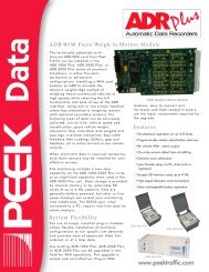
Chapter 5 — Theory of OperationFUNCTIONAL ORGANIZATIONRefer to the overall Functional Organization Block Diagram in Figure 1 and the ModulePartitioning Block Diagram in Figure 2, shown on page 31.Figure 1 – Model <strong>170E</strong>-<strong>ATC</strong> Functional Block Diagram30 U.S. <strong>Traffic</strong> <strong>170E</strong>-<strong>ATC</strong> Controller Operating Manual
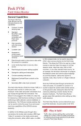
Functional OrganizationModule Partitioning Block DiagramFigure 2 – Model <strong>170E</strong>-<strong>ATC</strong> Modular Block DiagramU.S. <strong>Traffic</strong> <strong>170E</strong>-<strong>ATC</strong> Controller Operating Manual 31
Chapter 5 — Theory of OperationMODEL 68B02 CPU MODULE OPTIONWhen reading about these aspects of the <strong>170E</strong>-<strong>ATC</strong> CPU module, please refer to Figure3 (shown on page 38) and Schematic Diagram 450D4468 on page 127.NoteThe <strong>170E</strong>-<strong>ATC</strong> controller can be shipped with either of two CPU moduleoptions: the 68B02 CPU module described in this section, or the 68HC11 CPUmodule, which is described in the next section, starting on page 39.This module contains the following elements:a.) MPU and MPU Clockb.) Address and Control Decoding Logicc.) Bus Interface Componentsd.) Communications Componentse.) Memoryf.) Real Time Clock (RTC)g.) Down Time Accumulator (DTA)h.) Restart Timeri.) Status Portj.) Standby Power SupplyMPU & MPU Clock (MicroProcessor Unit)The MPU chip (U1) is a 6802 or 6808. This is an LSI microprocessor member of theMotorola 6800 family. It has an 8-bit data bus and is capable of directly addressing 64Kbytes of memory space. It contains an on-board clock oscillator and a small amount ofRAM.In this circuit the RAM in a 6802 is disabled by connecting the RAM Enable input (U1 pin36) to ground. The MPU clock is generated externally by a 6.144 MHz crystal-controlledclock oscillator module Y1. This is either connected directly to the MPU EXTAL input(U1 pin 39) or is frequency divided by 2 (to 3.072 MHz) in part of U11 before connectingto the MPU pin 39. Either of these two frequencies can be selected as the MPUoscillator input by means of a strapping option. These signals are then frequencydivided within the MPU chip to produce the system clock frequency of either 768 KHz or1.536 MHz which is available at U1 pin 37 as the Enable (E) signal.Address and Control Decoding LogicThis consists of the two programmable logic chips U12 and U13 and part of chip U16.These devices use all address lines A0 to A15, the R/W (Read/Write), VMA (ValidMemory Address) and 3 strapping option jumper inputs to generate complete addressdecoding for device selection and Bus Control functions. Together these chips generatethe following functions.RAMThe Valid Random Access Memory address chip select is available from U12 pin 17. Itis low whenever the MPU accesses the RAM (U2) contained on this card. For complete32 U.S. <strong>Traffic</strong> <strong>170E</strong>-<strong>ATC</strong> Controller Operating Manual
Model 68B02 CPU Module Optiondetails of the valid addresses, refer to the System Addressing Plan (page 16) for theparticular mapping options selected with the Configuration 1 and Configuration 2 jumperstraps.SO and S1These are coded outputs from U12 pins 22 and 24 and are for use by U13 to assist ingenerating complete decoding for that chip.ROMThe valid Read Only Memory address chip select is available from U12 pin 27. Thisoutput goes low whenever the MPU accesses the EPROM (U3) resident on this card.Refer to the System Addressing Plan (page 16) for complete details of the validaddresses for the particular configuration options selected on this card.A411This signal output from U12 pin 25 is only used internally by U12. It is high wheneveraddress bits A4 to A11 are all low.DTAMThis signal from U13 pin 15 goes low whenever the MPU requests a read of the DownTime Accumulator Minutes register at address $5000.DTARDTAR stands for ‘down time accumulator reset. This signal from U13 pin 16 goes highwhenever the MPU requests a reset of the Down Time Accumulator by writing toaddress $5000.VIOVIO stands for ‘valid input/output’. This signal from U13 pin 27 is active low for alladdresses in the range of the input and output interface boards as well as for the frontpanel interface. This covers reading and writing to addresses $5001 to $5008 andwriting to addresses $5009 to $500A.ACIA1This output from U13 pin 17 is an active low for all accesses of ACIA #1 (U4) ataddresses $6000 and $6001.ACIA2This output from U13 pin 18 is an active low for all accesses of ACIA #2 (U5) ataddresses $6002 and $6003 for normal operation, (with the COM2/3 jumper in thenormal position). With the jumper in the SWAP position, U5 is accessed at addresses$6004 and $6005.ACIA3This output from U13 pin 19 is an active low for all accesses of ACIA #3 (U6). This is ataddresses $6004 and $6005 for normal operation and addresses $6002 and $6003 withthe COM2/3 strap in the SWAP position.ACIA4This output from U13 pin 20 is an active low for all accesses of ACIA #4 (U7) ataddresses $6006 and $6007.U.S. <strong>Traffic</strong> <strong>170E</strong>-<strong>ATC</strong> Controller Operating Manual 33
Chapter 5 — Theory of OperationSTATThis output from U13 pin 22 is an active low whenever the MPU requests a read of theCPU STATus port at address $5FFF.RTCRESRTCRES stands for ‘real-time clock reset’. This output from U13 pin 23 goes lowwhenever the MPU resets the Real Time Clock by writing to address $5FFF.MBENMBEN stands for ‘memory bus enable’. This output from U13 pin 25 goes low wheneverthe MPU accesses any address for any device located on the Memory Bus. It is used tocontrol bus buffer chips U27, U28 and U29.IOBENIOBEN stands for ‘input/output bus enable’. This output from U13 pin 26 goes lowwhenever the MPU accesses any device on the I/O Bus. It is used to control buffer chipU30.DTASDTAS stands for ‘down time accumulator seconds’. This output from U13 pin 24 goeslow whenever the MPU requests a read of the Downtime Accumulator Seconds registerat address $500F.VMA.EThis is a logic low whenever both the system Enable (E) and Valid Memory Address arehigh. It is used on the memory bus and is available from U16 pin 11. This chip is also abuffer and so this signal is used to feed directly onto the memory control bus.Bus Interface ComponentsThe CPU Card has two separate off-card bus interface structures: one for the I/O andone for memory. Chips U27 and U28 buffer the 16 address bits for the memory buscontrolled by the MBEN signal. These chips are therefore active only when the MPU isaccessing devices on this bus. The memory data bus is buffered by U29, againcontrolled by MBEN so that it is only active for accessing devices on this bus. Datadirection is controlled by the system R/W line. When this is high, U29 passes data fromthe backplane to the card local data bus. VMA.E (described above) is available from U16pin 11 while Memory ReaD (MRD) is buffered in U16 and available at pin 8.The I/O Bus has its addresses (bits AO to A3) and two control lines IOEN (Input OutputENable) and IORD (Input Output ReaD) buffered by U35. The I/0 data bus is bufferedby U30 which is controlled by IOBEN and the system R/W line. The system clockEnable signal (E) is buffered by U16 and is available on the I/O backplane as E fromU16 pin 6.Communications ComponentsThese comprise the 4 Asynchronous Communications Interface Adaptor (ACIA) chipsU4 to U7; 3 RS-232C interface chips U8 to U10; and the baud rate clock generatingcircuitry made up of U11 and U24 with the clock rate selector jumpers CLKSEL1 toCLKSEL4. The CPU oscillator frequency of 3.072 MHz from U11 pin 13 is taken to a34 U.S. <strong>Traffic</strong> <strong>170E</strong>-<strong>ATC</strong> Controller Operating Manual
Model 68B02 CPU Module Optiondivide-by-5 section of U11 at pin 12. The output at 614.4 KHz is taken from pin 10 andconnected to a divide-by-2 section of U11 at pin 1. The output from this section is at afrequency of 307.2 KHz. This goes to the ACIA clock rate select jumpers and also to theinput of one section of the binary counter U24 pin 10. The outputs from U24 at pins 9, 7,6 and 5 are at frequencies of 153.6 KHz, 76.8 KHz, 38.4 KHz and 19.2 KHz respectively,as required for the clock select jumper arrays.Each ACIA has an IRQ output from pin 7. They are connected to the IRQ combiningchip U14 via jumpers so that each ACIA interrupt can be inhibited independently. Theoutput of U14 pin 6 is the MPU interrupt and is low whenever any of the 5 possiblesources of interrupt is low.MemoryThe memory chips on the CPU card are U2 and U3. U2 is a zero-power static RAM chipcontaining 32K bytes of RAM and an internal lithium battery for data retention. Refer tothe System Addressing Plan (Shown on page 16) for the address ranges for U2 providedby various strapping options.U3 is a 32K byte EPROM. Refer to the System Addressing Plan for the address rangesfor U3 provided by the various strapping options.Real Time Clock (RTC)The RTC clock signal at edge connector pin 44 is an approximate square wave with itsfalling edge occurring just after the zero crossing of the AC line negative half cycle(approximately 200°). This is connected to the negative transition trigger input of themonostable multivibrator chip U31 at pin 5. With the time constant of R11 and C3, U31generates a negative pulse at pin 7 of approximately 4.3 milliseconds. The positivegoingtransition of this pulse occurs at approximately 290° of the AC line phasing.This positive transition is used to trigger the RTC flip-flop U15 with U31 pin 7 connectedto the flip-flop input U15 pin 11. The output from U15 at pin 8 is the RTC IRQ. This isconnected to the system interrupt via U14 along with the 4 ACIA IRQs. The RTCinterrupt is reset by the MPU writing to address $5FFF generating the RTCRES signalconnected to U15 pin 13. A low at this point resets the flip flop to its normal high state atU15 pin 8.Down Time AccumulatorThe DTA is powered by the standby power supply (SBY) generated on the card. Itconsists of a CMOS crystal-oscillator U23, some gating logic U21, U22, U17 and U23,three frequency-divider chips U18, U19 and U20, and two octal data buffer chips U25and U26.Crystal Y2 with R8, R9, C1 and C2 control the crystal-oscillator frequency of 32.768 KHzwhich, with the Model <strong>170E</strong>-<strong>ATC</strong> power OFF, can be measured at Test Point TP1 on theoutput of U23 pin 11. The oscillator is normally running unless the DTA has reached afull count, at which time U23 pin 10 goes low inhibiting the oscillator to conserve standbypower.Under normal operating conditions, with the DTA having been reset so that it is not at afull count, FCNT is high. Also, both NMI and RES are high. NMI and RES areconnected to U23 pins 2 and 1 and therefore U23 pin 3 is low. This keeps U21 pin 10low and hence U23 pin 12 is low which gates the oscillator output from U23 pin 11 off.When a power failure occurs, first NMI and then RES go low, switching U21 pin 10 highU.S. <strong>Traffic</strong> <strong>170E</strong>-<strong>ATC</strong> Controller Operating Manual 35
Model 68B02 CPU Module OptionThese signals are combined in U32 to hold the gate drive voltage to Q2 low until afterthe 1.75 seconds monostable times out. If after this time, the RES line is still low (REShigh), the output of U32 pin 10 will go high and turn on Q2 forcing ROT low. However, ifthe RES signal goes high prior to the 1.75 seconds timing out, then ROT will remainhigh.The second half of the monostable (U34 pins 1 to 7) is a 50 milliseconds timer. It istriggered on the positive-going transition of the RES signal unless it is inhibited by the1.75 seconds timer not having timed out. When this timer is triggered, its Q output (pin7) goes low for 50 milliseconds, causing U32 pin 10 to go high for that time. The ROToutput is thereby held low for 50 milliseconds after the controller commences its restartsequence.STATus PortThis port is a single octal inverting buffer chip U33. When the CPU requests a read ofaddress $5FFF, the data on the input of this buffer is transferred to the local data bus inits inverted state.The data on the input of this port is the state of the 4 ACIA interrupts, the Configurationjumper status (MAP), the RTC full count status (FCNT) and the RTC interrupt status(RTCIRQ). The remaining bit (bit 5) is normally pulled high via RP1 pin 4. However, asan option, it may be either strapped low or connected to the Configuration 2 jumperstatus (MAP2).Standby Power SupplyTwo standby power supplies are generated locally on the CPU card for use by the DTAand Restart Timer. Each consists of a supercapacitor C8 or C10 and charging circuitryR1, R12, R17, R18, Q1 Q3 and Q4.Under normal operating conditions, the RES line is high and applied to the gate of Q1,turning it ON. This in turn switches Q3 and Q4 on, connecting the standby supplies tothe 5V power supply with only a very small voltage loss. R1 and R17 limit the basecurrent in Q3 and Q4. With the standby supply at the same voltage as the 5V supply,supercapacitors C8, and C10 rapidly charge to near 5V with R12 or R10 limiting thecharge current and ensuring minimum voltage drop across Q3 and Q4.On power failure, RES goes low turning off Q1, Q3 and Q4, thereby isolating the standbysupplies from the 5V supply. Supercapacitors C8 & C10 provide the energy to power thecircuits on the standby supplies.Clock Activity IndicatorThe clock activity LED, D1 will flash at 7.5Hz so long as the CPU clock is running. Thissignal is derived from chips U15 and U11 driven by a 75Hz clock from U24 pin 1.U.S. <strong>Traffic</strong> <strong>170E</strong>-<strong>ATC</strong> Controller Operating Manual 37
Chapter 5 — Theory of OperationCPU Module Block DiagramFigure 3 – Model <strong>170E</strong>-<strong>ATC</strong> CPU Block Diagram38 U.S. <strong>Traffic</strong> <strong>170E</strong>-<strong>ATC</strong> Controller Operating Manual
Model 68HC11 CPU Module OptionMODEL 68HC11 CPU MODULE OPTIONThe Model HC-11 CPU Board is designed to replace the 6800 CPU board that was usedin prior versions of the Model <strong>170E</strong>-<strong>ATC</strong> Controller. The HC-11 easily replaces the 6800CPU by simple removing the 6800 CPU board and installing the new Model HC-11 CPUboard in the same slot.The Model 68HC11 CPU is now the standard CPU shipped with most U.S. <strong>Traffic</strong><strong>170E</strong>-<strong>ATC</strong> controllers.FeaturesReplaces 6800 CPU Board in the <strong>170E</strong>-<strong>ATC</strong> Controller.Uses a 68HC11F1 MCU with a clock frequency of 9.8304MHz.Provides 64K EPROM and 24K ZRAM.Replaces the four obsolete ACIAS with a Quad UART.Feature and Location switches are provided.LEDs indicate correct operation.All power supplies are Transorb protected on the board.Battery backed – clock timing chip.The HC-11 CPU Board is code compatible with the 6800 CPU and uses the same reset,NMI and start-up circuitry. However, start-up vector routines must be modified by thesoftware vendor. The HC-11 CPU Board provides 30K x 8 of ZRAM (28K contiguous),32K x 8-bytes of EPROM plus an additional 32K x 8-bytes of bank switched EPROM anda real time clock. There is a user defined memory map for software developers tofollow. There is also a 4K x 8-byte jumper option to allow transfer of data to a remotedual port location. Feature and Location switches, normally found on the 412C PROMmodule, have been located on the HC-11 CPU Board. There is a software controlledLED indicator located on the front of the HC-11 to monitor operations. All powersupplies are protected by Transorbs on the HC-11 CPU Board.ApplicationsThe HC-11 CPU Board may be used for all applications that the original 6800 CPUboard provided to the transportation industry. The HC-11 CPU Board provides a meansfor 170 customers to continue using <strong>170E</strong>-<strong>ATC</strong> Controllers without the added expense ofpurchasing high cost replacements units. In addition, software developers can addmany new features with the additional 32K bank switched EPROM and the 24K ofcontiguous ZRAM memory.DescriptionMCUThe MCU is a Motorola 68HC11F1 or equivalent. The MCU operates at a crystalfrequency of 9.8304MHz.EPROMThe HC-11 CPU Board has a ZIF socket that houses a 128K x 8-byte EPROM. With the128K EPROM installed, the program has access to an extra 32K x 8-bytes via bankswitching. The bank is activated by a write to location $7002 which causes the memoryU.S. <strong>Traffic</strong> <strong>170E</strong>-<strong>ATC</strong> Controller Operating Manual 39
Chapter 5 — Theory of Operationto go to the upper 64K of the 128K EPROM. The status of the bank switch is read onthe IRQ status register - bit six.ZRAMThe HC-11 CPU Board has a 32K ZRAM (Dallas 1644 or equivalent) with continuouslocation from $0000-6FFF. This provides the software developer with 28K x 8-bytes ofZero power RAM. Clock addresses are in the I/O map locations at $7FF8-7FFF. Inaddition, a jumper selection allows the switching of location $6000-6FFF (4K) to aremote Dual port RAM. The status of the jumper position is read on the IRQ statusregister - bit five.CommunicationThe Quad UART chip is installed on the HC-11 CPU Board. This is a 16C654. TheUART operates at a clock frequency of 9.8304 MHz with baud rates being softwareselectable. An IRQ status register is provided as specified by CALTRANS.Feature and Location SwitchesFeature and Location switches are provided on the front portion of the HC-11 CPUBoard. Each switch is an eight-position front reading dip switch. The Feature switch isaddressed at $7000 and the Location switch is addressed at $700A. Each switch isdirectly connected to Port E and Port A of the HC-11 MCU.LED IndicatorThere is one LED indicator located on the front portion of the HC-11 CPU Board. ThisLED is controlled via a software output from Port G bit 3 of the HC-11 MCU.40 U.S. <strong>Traffic</strong> <strong>170E</strong>-<strong>ATC</strong> Controller Operating Manual
Model 68HC11 CPU Module OptionTable 18 — HC-11 Base Memory MapLOCATION BLOCK SIZE FUNCTION NOTES$0000 - $5FFF 24K 170 RAM CPU BOARD RAM$6000 - $6FFF 4K RAM INT/EXT SELECTABLE DUAL PORT RAM$7000 - $73FF 1K CONFIG REG + RAM INITIATE IMMEDIATELY ON START UP$7400 - $75FF 512 BYTES I/O EXTERNAL I/O FUNCTIONS$7600 - $7FFF 2K RAM CPU BOARD RAM$8000 - $FFFF 32K EPROM CPU BOARD PROM MEMORYDETAILED ALLOCATION$7000 1 BYTE SWITCH FEATURE SWITCH/HC-11 PORT E$700A 1 BYTE SWITCH LOCATION SWITCH/HC-11 PORT A$7002 1 BYTE BANK SELECT BANK SWITCH SELECT HC-11 PORT G-BIT 1$7002 1 BYTE STATUS INDICATOR HC-11 PORT G – BIT 3 1=ON$7000 - $705F 96 BYTES CONFIG. REG. 68HC-11 CONFIG REGISTERS$7060 - $73FF 1K (-96) RAM 68HC-11 RAM (VOLATILE)$7400 1 BYTE DTA MINUTES I/O DTA READ MINUTES$740F 1 BYTE DTA SECONDS I/O DTA READ SECONDS$7401 - $740A 10 BYTES I/O I/O READ AND WRITE$7420 - $743F 32 BYTES UART SERIAL PORTS 1-4$7500 - $7507 8 BYTES DPR DUAL PORT SEMAPHORES$75FF 1 BYTES IRQ/STAT 60HZ RESET AND IRQ STATUS PORT$7600 - $7FF7 2K (-8) RAM CPU BOARD RAM$7FF8 - $7FFF 8 BYTES CLOCK/CALENDAR CLOCK/CALENDAR OPERATIONTable 19 — HC-11 Memory Map - Los Angeles County specificationMAP BANK 2 BANK 1 MEMORY/SIZE STANDARD ADDRESSES1 HIGH2 HIGH3 LOW4 LOWHIGH NRAM (28K)0000-6FFFMCU REGISTERS (96 BYTES) 7000-705FVOLATILE CPU RAM (928 BYTES) 7060-73FFI/O and CONTROL (511 BYTES)7400-75FFNRAM 2K7600-7FFF(1) xxxx PROM 32K (1)8000-(1)FFFFLOW NRAM 28K0000-6FFFMCU REGISTERS (96 BYTES) 7000-705FVOLATILE CPU RAM (928 BYTES) 7060-73FFI/O and CONTROL (511 BYTES)7400-75FFNRAM 2K7600-7FFF(0)xxxx PROM 32K (0)8000-(0)FFFFHIGH NRAM 8K 0000-1FFF(1)xxxx PROM 16K (1)2000-(1)5FFFNRAM 4K6000-6FFFMCU REGISTERS (96 BYTES) 7000-705FVOLATILE CPU RAM (928 BYTES) 7060-73FFI/O and CONTROL (511 BYTES)7400-75FFNRAM 2K7600-7FFF(1)xxxx PROM 32K (1)8000-(1)FFFFLOW NRAM 8K 0000-1FFF(0)xxxx PROM 16K (0)2000-(0)5FFFNRAM 4K6000-6FFFMCU REGISTERS (96 BYTES) 7000-705FVOLATILE CPU RAM (928 BYTES) 7060-73FFI/O and CONTROL (511 BYTES)7400-75FFNRAM 2K7600-7FFF(0)xxxx PROM 32K (0)8000-0FFFFU.S. <strong>Traffic</strong> <strong>170E</strong>-<strong>ATC</strong> Controller Operating Manual 41
Chapter 5 — Theory of OperationNote The following notes apply to Table 19.• Bank 1 is MCU port G bit 0 output• Bank 2 is MCU port G bit 1 output• After reset, the state of bank 1 is high and bank 2 is low (map 3).Functional OrganizationRefer to Schematic Diagram 450D4490, on page 129.HC-11 CPU ModuleThe HC-11 Board contains the following elements:MCU and MCU ClockAddress and Control Decoding LogicBus Interface ComponentsCommunications ComponentsMemoryReal Time Clock (RTC)Down Time Accumulator (DTARestart TimerStatus PortFeatures & Locations Switch PortsStandby Power SupplyActivity LEDMCU & MCU Clock (MicroController Unit)The MCU chip (U1) is a type 68HC11F1 which is a LSI microcontroller member of theMotorola 68HC11 family. It has an 8-bit data bus and is capable of directly addressing64K bytes of memory space. It contains an on-board clock oscillator and a small amountof RAM.The MCU clock is generated externally by a 9.8304 MHz crystal-controlled clockoscillator module U30 which is connected directly to the MPU EXTAL input (U1 pin 6).The oscillator signal is frequency divided within the MCU chip to produce the systemclock frequency of 2.4576 MHz which is available at U1 pin 4 as the Enable (E) signal.Address and Control Decoding LogicThis consists of the two programmable logic chips U10 and U11 and part of chip U28.These devices use all address lines A0 to A15, the R/W (Read/Write), E (MCU Enable),2 strapping option jumper inputs (MAP, labeled 6000-6FFF) and (!SWAP, labeled COM2/3), and 2 bank control outputs (BNK1 & BNK2) from the MCU. These are used togenerate complete address decoding for device selection and Bus Control functions.Together these chips generate the following functions:!RAMThe Valid Random Access Memory address chip select is available from U10 pin 20. Itis low whenever the MCU accesses the RAM (U3) contained on this card. For complete42 U.S. <strong>Traffic</strong> <strong>170E</strong>-<strong>ATC</strong> Controller Operating Manual
Model 68HC11 CPU Module Optiondetails of the valid addresses, refer to Table 18 on page 41 for the particular mappingoptions selected with bank switching, and map inputs.BANK 2This bank select output for the EPROM chip U4 is available from U10 pin 15. Its state isdependant upon the BNK2 and MAP inputs.!ROMThe valid Read Only Memory address chip select, available from U10 pin 17. Thisoutput goes low whenever the MCU accesses the EPROM (U4) resident on this card.Refer to Table 18 on page 41 for complete details of the valid addresses for theparticular configuration options selected on this card.EXTMAThis signal output from U10 pin 16 is used by U28 to generate the equivalent of the!VMA.E signal required by legacy external memory cards.740XThis signal from U10 pin 19 goes high whenever the MCU requests an access ofaddresses $7400 to $740F. It is used as an input to U11 for further address decoding.$75FXThis signal from U10 pin 22 goes high whenever the MCU requests an access ofaddresses $75F0 to $75FF. It is used as an input to U11 for further address decoding.!MBEN (Memory Bus Enable)This signal from U10 pin 23 is active low for all valid external memory addresses.!UARTThis output from U10 pin 24 is an active low for all accesses of the Quad UART (U2) ataddresses $7420 to $743F.UA3 & UA4These outputs from U11 pins 20 & 21 are the address bits A3 & A4 for the Quad UART(U2). They are identical to A3 & A4 when the COM 2/3 jumper is in the “normal” positionand are swapped when the jumper is in the “SWAP” position.!DTAMThis signal from U11 pin 19 is an active low whenever the MCU requests a read of thedowntime accumulator minutes register at address $7400.DTARThis signal from U11 pin 18 is an active high whenever the MCU requests a reset of thedowntime accumulator by writing to address $7400.!STATThis output from U11 pin 16 is an active low whenever the MCU requests a read of theCPU STATus port at address $75FF.U.S. <strong>Traffic</strong> <strong>170E</strong>-<strong>ATC</strong> Controller Operating Manual 43
Chapter 5 — Theory of Operation!RTCRES (Real Time Clock RESet)This output from U11 pin 17 goes low whenever the MCU resets the Real Time Clock bywriting to address $75FF.!IOBEN (Input Output Bus ENable)This output from U11 pin 22 goes low whenever the MCU accesses any device on theI/O Bus. It is used to control buffer chip U19.!VIO (Valid Input/Output)This signal from U11 pin 14 is an active low for all addresses in the range of the inputand output interface and the front panel interface boards. This covers reading & writingto addresses $7401 to $740A.!DTAS (Down Time Accumulator Seconds)This output from U11 pin 23 goes low whenever the MCU requests a read of theDowntime Accumulator Seconds register at address $740F.!VMA.EThis is a logic low whenever both the system Enable (E) and Valid External MemoryAddress (EXTMA) are high. It is used on the memory bus and is available from U28 pin11. This chip is also a buffer and so this signal is used to feed directly onto the memorycontrol bus.Bus Interface ComponentsThe HC-11 CPU Card has two separate off-card bus interface structures: one for the I/Oand one for memory.Chips U5 and U6 buffer the 16 address bits for the memory bus controlled by the !MBENsignal. These chips are therefore active only when the MCU is accessing devices onthis bus.The memory data bus is buffered by U8, again controlled by !MBEN so that it is onlyactive for accessing devices on this bus. Data direction is controlled by the system R/Wline. When this is high, U8 passes data from the backplane to the card local data bus.!VMA.E (described above) is available from U28 pin 11 while Memory ReaD (MRD) isbuffered in U28 and available at pin 6.The I/O Bus has its addresses (bits A0 to A3) and two control lines !IOEN (Input OutputEnable) and IORD (Input Output ReaD) buffered by U7. The I/O data bus is buffered byU9 which is controlled by !IOBEN and the system R/W line. The system clock Enablesignal (E) is buffered by U28 and is available on the I/O backplane as !E from U28 pin 3.Communications ComponentsThese comprise the Quad Universal Asynchronous Receiver Transmitter (UART) chipU2, three RS232 interface chips U12 to U14, and the RS485 buffer chip U32. In additionthere is an RS485 buffer chip U31 to buffer the serial communications output of the MCUchip U1.All the RS485 I/O signals are connected to a header (HD1) on the front edge of the CPUmodule. This header allows for future expansion for a front panel LCD display card anda front panel mounted RS485 (C50) communications connector.Note that when an external device is plugged into C50, pin 10 on HDR1 will be shortedto ground and Q6 (normally ON) will be turned off. This will then activate U32 and44 U.S. <strong>Traffic</strong> <strong>170E</strong>-<strong>ATC</strong> Controller Operating Manual
Model 68HC11 CPU Module Optiondeactivate U14, effectively switching COM 4 from the RS232 rear panel connector C40to a front panel RS485 connector C50.The MCU crystal oscillator frequency of 9.8304 MHz is connected to the UART XTALIinput (pin 35). This enables the UART to generate many baud rates under softwarecontrol of the MCU.The UART has a single interrupt output which is combined with the real time clock IRQin U23-D and Q5. The UART IRQ is also connected to the Status Port U29 pin 2 so thatthe MCU may easily determine whether an IRQ source is due to the UART or the RTC.MemoryThe memory chips on the HC-11 CPU Board are U3 and U4. U3 is a zero-power staticRAM chip containing 32K bytes of RAM with 8 bytes used by an internal clock/calendar.An internal lithium battery is used for data retention. Refer to the System AddressingPlan (page 16) for the address ranges for U3 provided by various mapping options.U4 is a 128K byte EPROM connected to present up to 4 X 32K banks of EPROM.again, refer to the System Addressing Plan for the address ranges for U4 provided bythe various mapping options.Real Time Clock (RTC)The RTC clock signal at edge connector pin 44 is an approximate square wave with itsfalling edge occurring just after the zero crossing of the AC line negative half cycle(approximately 200°). This is connected to the negative transition trigger input of themonostable multivibrator chip U24 at pin 5. With the time constant of R8 and C6, U31generates a negative pulse at pin 7 of approximately 4.3 milliseconds. The positivegoingtransition of this pulse occurs at approximately 290° of the AC line phasing.This positive transition is used to trigger the RTC flip-flop U25 with U24 pin 7 connectedto the flip-flop input U25 pin 11. The output from U25 at pin 8 is the RTC IRQ. This isconnected to the system interrupt via U23 & Q5 along with UART IRQ. The interrupt isreset by the MCU writing to address $75FF generating the !RTCRES signal connectedto U25 pin 13. A low at this point resets the flip flop to its normal high state at U25 pin 8.Downtime AccumulatorThe DTA is powered by the standby power supply generated on the card. It consists ofa CMOS crystal-oscillator U23, some gating logic U19, U16, U18 and U23, threefrequency-divider chips U17, U21 and U22, and two octal data buffer chips U15 andU20.Crystal Y1 with R4, R5, C2 and C3 control the crystal-oscillator frequency of 32.768 KHzwhich, with the Model <strong>170E</strong>-HC11 power OFF, can be measured at Test Point TP1 onthe output of U23 pin 4. The oscillator is normally running unless the DTA has reacheda full count, at which time U16 pin 13 goes low inhibiting the oscillator to conservestandby power.Under normal operating conditions, with the DTA having been reset so that it is not at afull count, !FCNT is high. Also, both !XIRQ and !RES are high. !XIRQ and !RES areconnected to U23 pins 9 and 8 and therefore U23 pin 10 is low. This keeps U19 pin 10low and hence U23 pin 5 is low which gates the oscillator output from U23 pin 4 off.When a power failure occurs, first !XIRQ and then !RES go low, switching U23 pin 10high and gating the oscillator output from U23 pin 4 on. This will remain on until eitherthe counters reach a full count or power is restored and both the !XIRQ and !RESsignals are high again.U.S. <strong>Traffic</strong> <strong>170E</strong>-<strong>ATC</strong> Controller Operating Manual 45
Chapter 5 — Theory of OperationThe DTA counter stages operate as follows. The first stage U22 divides the oscillatorfrequency down to 8 Hz from U22 pin 1. This is used as the clock signal for the DTAseconds counter U21. Note that for diagnostic testing, U22 has an output at 8192 Hzfrom pin 7. This can be connected to the seconds counter as its input clock by shortingthe two DTA test points on the PC card. This will allow the DTA to reach full count inapproximately 15 seconds.The Q4 through Q9 outputs from the seconds counter (U21) are the seconds output ofthe DTA. The 32S, 16S and 8S outputs are used as inputs to U19 (pins 5, 4 and 3).These are all high at 56 seconds and this also turn U19 pin 6 high. This is used as theclock input to the minutes counter and as an input to another section of AND gate U19 atpins 2 and 8.When the 4 seconds count then goes high at pin 1 of U19 (at 60 seconds), U19 pin 9also goes high driving OR gate output U18 pin 10 high. This is used to reset bothcounters U21 and U22, driving all their outputs back to a low state and causing U19 pin6 to go low. This negative transition clocks the minutes counter U17, incrementing itscount by 1 minute.When the minutes counter U17 contains a full count of 255 minutes, the 8-input NANDgate output at U16 pin 13 goes low. This drives U19 pin 10 low and inhibits the oscillatorfrom passing through to the counter U22. Also the oscillator is gated off to conservepower when U23 pin 9 goes low.The counters can be reset by the CPU writing to address $7400. This logic high pulse isapplied to U18 pin 2. Pin 3 of U18 is normally pulled low by R2. Therefore, U18 pin 1 isnormally high. When a logic high pulse is applied to pin 2, pin 1 goes low. This isinverted at the output of U18 pin 13 to generate a logic high pulse. This is used as theminutes counter reset at U17 pin 11 and applied to U18 pin 8 to generate the secondscounter reset.This pulse is also applied to U18 pin 3 via capacitor C1. The effect of this is to stretchthe pulse width of the reset pulse to the slow CMOS counter chips U17, U21 and U22.The RES input to U18 pin 11 prevents transients, (generated during power-up & powerdown),from resetting the counters.Buffers U15 and U20 enable the CPU to read the state of the minutes and secondscounters.Restart TimerThe Restart Timer comprises CMOS devices U26 and U27, timing components R10,R11, C5 and C7 and transistor Q4.Under normal operating conditions, the !Q outputs from each half of the dual monostablemultivibrator U27 pins 9 and 7 are high and the buffered RES signal from U26 pin 4 islow.These signals are combined in U26A and U26D to give a logic low signal to the gate oftransistor Q4. This transistor is therefore switched off and its drain output ROT is pulledhigh by R9.When a non-maskable interrupt is detected (!XIRQ goes low), the 1.75 secondmonostable U27/B is triggered giving a logic low signal at its !Q (pin 9) output. Thissignal inhibits the other half of U27 so that its !Q output (pin 7) remains high.These signals are combined in U26 to hold the gate drive voltage to Q4 low until afterthe 1.75 seconds monostable times out. If after this time, the !RES line is still low (RES46 U.S. <strong>Traffic</strong> <strong>170E</strong>-<strong>ATC</strong> Controller Operating Manual
Model 68HC11 CPU Module Optionhigh), the output of U26 pin 11 will go high and turn on Q4 forcing ROT low. However, ifthe !RES signal goes high prior to the 1.75 seconds timing out, then ROT will remainhigh.The second half of the monostable U27/A is a 50 milliseconds timer. It is triggered onthe positive-going transition of the !RES signal unless it is inhibited by the 1.75 secondstimer not having timed out.When this timer is triggered, its !Q output (pin 7) goes low for 50 milliseconds, causingU26 pin 11 to go high for that time. The ROT output is thereby held low for 50milliseconds after the controller commences its restart sequence.Status PortThis port is a single octal inverting buffer chip U29. When the CPU requests a read ofaddress $75FF, the data on the input of this buffer is transferred to the local data bus inits inverted state.The data on the input of this port is the state of the UART interrupt, the Configurationjumper status (MAP), the RTC full count status (!FCNT) the RTC interrupt status(!RTCIRQ), the COM2/3 (!SWAP) jumper, and the MPU BNK1 output. The remainingbits (bits 2 and 3) are pulled high.Feature & Location SwitchesThe “Feature & Location” switches (consisting of SW1, SW2, RP1 & RP2) are directlyread by the MCU ports A & E.Standby Power SupplyStandby power is generated locally on the CPU card for use by the DTA and RestartTimer. It consists of a 1 Farad supercapacitor C4 and charging circuitry R6, R7, Q2 andQ3.Under normal operating conditions, the !RES line is high and applied to the gate of Q2,turning it ON. This in turn switches Q3 on, connecting the standby supply to the 5Vpower supply with only a very small voltage loss. R6 limits the base current in Q3.With the standby supply at the same voltage as the 5V supply, supercapacitor C4 rapidlycharges to near 5V with R7 limiting the charge current and ensuring minimum voltagedrop across Q3.On the power failure, !RES goes low turning off Q2 and Q3, thereby isolating thestandby supply from the 5V supply. Supercapacitor C4 provides the energy to power thecircuits on the standby supply.Activity LEDThis LED flashes to show MCU activity. The circuitry consists of CR1 and Q1 which aredriven directly by the MCU Port G bit 3 (U1 pin 25).Mapping OptionsThere are two hardware-controlled mapping options on the HC-11 CPU Board. Theseare the $6000 - $6FFF Configuration jumper and the COM 2/3 jumper. In addition,memory mapping is under software control of the MCU by means of the two Bankswitching outputs BNK1 and BNK2.U.S. <strong>Traffic</strong> <strong>170E</strong>-<strong>ATC</strong> Controller Operating Manual 47
Chapter 5 — Theory of OperationConfiguration ($6000 - $6FFF) JumperIn the “Internal” position, these addresses are normally RAM memory located on theCPU board. In the “External” position, these addresses are normally located off of thisboard.However, when BNK2 bank switching output from the MCU is low, the configurationjumper function is not active and the BNK2 function takes precedence – refer to 5.13.4below.COM 2/3 JumperWhen this jumper is in the “Normal” position, COM 2 (C20) is accessed by MCUaddresses $7428 - $742F and COM 3 (C30) is accessed by MCU addresses $7430 -$7437. In the “SWAP” position, the MCU address for these communications ports areswapped.BNK 1 – EPROM Bank SwitchingThe EPROM (U4) is a 128K x 8 bit chip which is set up as 2 x 64K banks controlled byBNK1. Normally only the top 32K of these memory banks are active. BNK1 is normallyhigh which means that the program memory is contained in the top 32K of the 128K chipmemory space. When BNK1 is low, the lower 64K of the chip is in the memory map withonly the top 32K of that being accessed.BNK 2This pin is normally high resulting in memory mapping as described above. If this line ispulled low, then a 20K block of RAM memory from $2000 - $6FFF is disabled andswitched to the EPROM chip. This also disables off card memory access from $6000 to$6FFF with the configuration jumper.48 U.S. <strong>Traffic</strong> <strong>170E</strong>-<strong>ATC</strong> Controller Operating Manual
Model 412C Program ModuleMODEL 412C PROGRAM MODULEThe Model 412C Program Module is designed to be installed in the Model <strong>170E</strong>-<strong>ATC</strong>and provides a variety of memory types and sizes as well as other features to enhanceoperation. Features of the Model 412C Program Module include a Real Time ClockAdjust circuit (RTCA), a battery voltage monitor and programmable switches for use asprogram feature selection or intersection/controller identification.General CharacteristicsThe Model 412C Program Module contains four sockets to accommodate variousmemory devices (EPROMs, EEPROMs, RAMs or Nonvolatile RAMs) in sizes from 8K x8 to 32K x 8. RAM memory integrity during power down is maintained by usingNonvolatile RAMs or the module battery for standard RAMs. Five different memorymaps are available with the standard decoder PAL devices. Custom memory mappingis available by changing the decoder PAL programming. Standard memory mapping isshown in Figure 4 on page 54.InstallationNote Before installing or removing any modules of the model <strong>170E</strong>-<strong>ATC</strong>(including the Program Module), switch the unit’s power off.The only adjustments to be made for installation are to set the "Locations" and"Features" DIP switches as required by the particular software package.AdjustmentsJumpers are normally factory set and, unless a change in memory mapping or types isrequired, these should not be touched. If they do need to be changed, refer to Figure 4.The only other adjustments are the RTCA frequency-adjusting trimmer capacitor C28,and the +5V regulator-adjusting trimpot R24. These are also factory set and should notrequire further adjustment.System DescriptionThe circuitry of the 412C Program Module can be divided into discrete blocks as shownin Figure 5. The power supply system consists of the DC to DC converter, battery,power switches and controller power. The converter supplements the low 5V powerfrom the Model <strong>170E</strong>-<strong>ATC</strong> by converting the ample 12V Model <strong>170E</strong>-<strong>ATC</strong> supply.The Model <strong>170E</strong>-<strong>ATC</strong> address and data lines are buffered to interface the Model <strong>170E</strong>-<strong>ATC</strong> bus with the 412C Program Module devices. The address lines, the addressdecode logic and the system control lines are used to control the interface to theindividual memory and other features on the 412C Program Module.Since a Model <strong>170E</strong>-<strong>ATC</strong> Reset signal is not available at the 412C Program Moduleconnector, on-board power fail detection circuitry is used to prevent data corruptionduring power failures. Memory chips U2, U3 and U4 can be powered from either the+5V supply from the DC to DC converter or the battery switched standby supply. Thestandby supply to these sockets should only be enabled when conventional RAM chipsare installed.U.S. <strong>Traffic</strong> <strong>170E</strong>-<strong>ATC</strong> Controller Operating Manual 49
Chapter 5 — Theory of OperationDetailed Circuit OperationRefer to the Block Diagram shown in Figure 5 on page 55, and also the SchematicDiagram 450D4199.Power SupplyThere are 4 separate power sources on the 412C Program Module:(i) 5V Model <strong>170E</strong>-<strong>ATC</strong> PowerUsed to power the address and data buffer chips U10, U11 and U16.(ii) +12V Model <strong>170E</strong>-<strong>ATC</strong> PowerUsed to power the DC to DC converter to generate the local +5V supply required bymost devices. It is also used in conjunction with the battery power isolating diodes CR3and CR4 to power the power fail detector U23.(iii) +5V Local PowerGenerated by the DC to DC converter and used to power the majority of the devices onthe 412C Program Module.(iv) Standby PowerComprises two separate standby supplies (SBY and SBY1). The SBY supply is used tosupport conventional RAM devices installed in sockets U2, U3 or U4, and the writeprotection circuitry consisting of U5 and U20. The SBY1 supply is used for the RTCAdevices U6 through U9.DC to DC ConverterThis is a high efficiency switching regulator used to convert the controller +12V supply to+5V DC. It consists of the control and switching element U22, flywheel diode CR1,choke L1, filter capacitors C25 and C32, switching frequency control capacitor C12,feedback control resistors R12, R14 and R24 and current limiting control resistor R13.The filtered output DC voltage is divided in R12, R14 and trimpot R24 and fed back tothe input of the comparator at U22 pin 5. This voltage is compared to the internalreference voltage of U22 and whenever it is low, additional power is switched to theoutput of the regulator. R24 is adjusted to give 5V across C25.Standby Power SuppliesUnder normal operating conditions, the output of U23 pin 7 is high (at +12 volts). Thisvoltage forward biases the base-emitter junctions Q3 and Q4 via limiting resistors R22and R23. Q3 and Q4 are turned on, connecting the SBY and SBY1 to the +5V supply.The output of U23 pin 7 is also connected to the base of transistor Q5 via a resistivedivider network R19 and R20. Under normal conditions, this causes the emitter-basejunction of Q5 to become reverse biased, turning Q5 off and isolating the battery fromSBY.When a power failure is detected, RES (U23 pin 7) goes to ground. This switches Q3and Q4 off, isolating SBY and SBY1 from the +5V supply. Q5 is also switched on,connecting SBY to the battery voltage. SBY1 is also connected to SBY when SW3 isswitched on.50 U.S. <strong>Traffic</strong> <strong>170E</strong>-<strong>ATC</strong> Controller Operating Manual
Model 412C Program ModulePower Fail DetectorThe power fail detector comprises reference diode CR2, with its bias resistor R18,connected to the negative input of comparator U23. Precision resistive divider andhysteresis feedback network R15, R16 and R17 is connected to the positive input.Whenever the +12V supply exceeds 11 volts, the RES output (U23 pin 7) is high.Hysteresis in the feedback network maintains this state until the +12V supply falls below9 volts at which time the RES output goes low. The RES signal is used to control thepower switching for the two standby supplies and to set the write protection circuitry onpower failure.Write Protection CircuitryThe write protection circuitry comprises toggle flip flop U5 and OR gate U20. The flip-flopoutput U5 pin 9 is toggled under software control by writing to address $7000. When U5pin 9 is high, OR gate outputs U20 pins 6 and 8 are always high. These signals go to pin27 of U2, U3 and U4. If these are RAM devices then pin 27 is the WE signal and thisprevents any writes to the devices, protecting the memory contents. When U5 pin 9 islow, the input signals to U20 pins 5 and 9 pass through the OR gates unchanged toperform their normal functions in U2, U3 and U4.Under a power failure condition, RES is low. This is buffered by U20 (pins 11, 12 and 13)and applied to the set input U5 pin 10, forcing U5 pin 9 high and applying writeprotection to the RAM devices. The state of the write protect circuitry can be read at anytime by reading address 700E bit 6. This is located at U14 pin 8. The signal appliedhere is the Q output of U5 (pin 7) which is buffered and inverted by Q2 and pull-upresistor R11. A logic high at U14 pin 8 indicates that the write protect is active.Program SwitchesTwo 8-pole DIP switches, SW1 and SW2, are mounted on, and accessible through, thefront panel. These switches can be used by software packages to designate variousprogram features or intersection locations. When any switch is OFF, its output is pulledup to the +5V supply by an element of RP2 or RP3.When the switch position is ON, then these outputs are pulled to ground. The Model<strong>170E</strong>-<strong>ATC</strong> can read the state of these switches via the inverting 74HC540 buffers U17and U18 at addresses $7000 and $7001 respectively. The inverting buffer causes a logic1 to be read by the Model <strong>170E</strong>-<strong>ATC</strong> when a switch is ON.Battery MonitorThe battery voltage is buffered by transistor Q1 with pull-up resistor R5. This bufferedsignal is a logic low when a good battery is connected and is connected to pin 2 on U21.This is an inverting tri-state buffer and its output is connected to the card data bus. Theother inputs of the buffer are connected alternately to ground and +5V such that, when aread of this buffer at address $700E is made, the Model <strong>170E</strong>-<strong>ATC</strong> will read $55 when agood battery is installed and $54 if the battery is defective or not installed.Address and Data BuffersThe Model <strong>170E</strong>-<strong>ATC</strong> bus address signals BA0 to BA15 are buffered by U10 and U11,giving buffered 412C Program Module address bus signals A0 to A15. Resistor networksRP4 to RP7 provide input protection and logic level compatibility for these CMOSdevices. The data bus signals D0 to D7 are buffered by the tri-state invertingbi-directional buffer U16. Data direction is controlled by the R/W signal and the buffer isactivated when VBA is low.U.S. <strong>Traffic</strong> <strong>170E</strong>-<strong>ATC</strong> Controller Operating Manual 51
Chapter 5 — Theory of OperationAddress DecodeAddress decoding and device control are achieved with PALs U24 and U25 and gatesU19, U20 and U26.U19 uses address bits A4 to A11 to produce the signal A411 at U19 pin 13. This signalis high when all of its A0 to A11 are low. A411 is used as one input to PAL U25 withA12 to A15, the system R/W, 3 map select signals S1 to S3 and a signal VMARD that isdescribed later.The outputs of U25 are the 4 memory device select signals MEM1 to MEM4, VMEMsignal, signals to control the levels of U1 pin 27 and U2 pin 27 and a signal FN that islow whenever the Model <strong>170E</strong>-<strong>ATC</strong> address is in the range $7000 to $700F inclusive.VMEM is low whenever one of MEM1 to MEM4 is low.U1 pin 27 is address bit A14 whenever the memory mapping is for a 27256 device insocket U1, and a logic 1 otherwise. U2 pin 27 is a logic 1 when the memory mappingcalls for an EPROM in socket U2 and is the write enable signal otherwise. This signal iswrite protected during power failure or under software control by combining it with thewrite protect signal in U20.The output of U20 pin 6 drives the memory device in socket U2. The standard U25device normally supplied decodes 5 memory maps as shown in Figure 4. Other mapsare available by replacing U25 with a PAL containing a different program.The PAL decoder U24 uses the block address signal FN from U25, address bits A0 toA3, the VMEM signal from U25 and system control lines R/W and VMA* as inputs. Theoutputs are the write protect flip-flop toggle signal WPT, the Real Time Clock AdjustReset signal CLRES, the DIP switch read enable signal DIPSW, the Real Time ClockAdjust Data read signals 700BC and 700DE, battery monitor read control signal BTMONand signals VBA and VMARD.CLRES is inverted by U26 (4, 5, 6) before being used as the reset signal for U6 and U7.Address bit A0 is inverted in U2A (11, 12, 13). Address A0 or A0 and signals 700BC,700DE or DIPSW are combined to enable U12, U13, U14, U15, U17 and U18. Thebattery monitor device U21 is enabled by signal BTMON. The signal VBA enables thedata bus buffer U16. This signal is asserted (low) for any write cycle, or for a read of avalid memory device on the 412C Program Module. The VMARD signal is low for allread cycles and goes low delayed by VMA* for writes only. This is used by U25 tosynchronize the timing of memory writes with the CPU clock.Memory DevicesThe devices shown in the schematic reflect the memory map 2 option. Other deviceoptions are shown in the memory mapping displayed in Figure 4 on page 54 and in the“Alternative Memory Types” topic shown on page 53.Real Time Clock Adjust (RTCA)The RTCA comprises U6 to U9, U12 to U15, Y1, R3, R25, R26, C3 and C28.U9 is a crystal-controlled oscillator divider that uses crystal Y1 with R3, C3 and adjustingtrimmer C28 to produce a 60Hz signal at U9 pin 14. This clock signal is fed to the binarycounters U7 and U6 via isolating resistor R26 and U8 which functions as a buffer and fullcount clock inhibition circuit. When CL21 to CL24 are all high, U8 pin 13 goes lowinhibiting the clock signal from passing through U8 at pin 1. The buffered clock signal isused as the clock for the 12-bit binary counter U7 and the CL12 output from U7 pin 1 isused as the clock input for the second binary counter U6.52 U.S. <strong>Traffic</strong> <strong>170E</strong>-<strong>ATC</strong> Controller Operating Manual
Model 412C Program ModuleThe 24 outputs CL1 to CL24 from U6 and U7 are isolated and buffered from the 412CProgram Module data bus by the 74BCT541 3-state buffer devices U12 to U14. Theinputs to these buffers permit a voltage in excess of the supply voltage without causingloading effect. This prevents the battery from being loaded when the SBY1 supply isconnected to the oscillator and divider devices and +5V supply to the buffer devices hasfailed.The crystal frequency is adjusted to precisely 15.36 KHz with trimmer capacitor C28.This is achieved by adjusting C28 while observing the frequency at test point a. Highspeed clocking of the RTCA for test purposes can be achieved by installing a link a-b for960 Hz clock or between b-c for 15.36 KHz clock.MaintenanceThe 412C Program Module does not require any routine adjustments or specialmaintenance procedures. However, a routine inspection should be conducted to ensurethat plug-in devices are properly seated and not loose and to remove any excessive dirtcollection.Alternative Memory TypesNOTE: In the following tables, for Sockets U1 to U4, "X" indicates a "don't care" state forthe strap.SOCKET U1MAPMEMORY1 2764 EPROM2 27128 EPROM3, 4, 5 27256 EPROMSOCKET U2MAP MEMORY U2 PWR PIN 26(+5V/SBY)(de/ef)1 2764 EPROM +5V X2 27128 EPROM +5V de3 Not Used X X4 1225 NOVRAM +5V X6264 RAM SBY ef2864 EPROM +5V X5 6264 RAM SBY efSOCKET U3MAP MEMORY U3 PWR(+5V/SBY)1,2,3,4,5 1225 NOVRAM +5V6264 RAM SBY2864 EPROM +5VSOCKET U4MAP MEMORY U4 PWR PIN 26(+5V/SBY)(256K/64K)1,2,3,4,5 6264 RAM SBY 64K62256 RAM SBY 256K2864 EEPROM +5V X1225 NOVRAM +5V X1225 NOVRAM +5V 256KU.S. <strong>Traffic</strong> <strong>170E</strong>-<strong>ATC</strong> Controller Operating Manual 53
Chapter 5 — Theory of Operation412C Program Module memory Map and Block DiagramMemorySelect12345Jumper Pattern#1#2#3ININOUTOUTININOUTOUTINOUTOUTOUTINOUTINMemory TypeAddress RangeMemory TypeAddress RangeMemory TypeAddress RangeMemory TypeAddress RangeMemory TypeAddress RangeU12764E000 - FFF27128C000 – FFFF272568000 – FFFF272568000 – FFFF27256C000 – FFFFU22764C000 – DFFF271288000 – BFFF--12253000 – 4FFF6264A000 - BFFFU312257010 – 7FFF12257010 – 7FFF12257010 – 7FFF12257010 – 7FFF12257010 – 7FFFU46264 or 622561000 – 4FFF6264 or 622561000 – 4FFF6264 or 622561000 – 4FFF6264 or 622561000 – 2FFF6264 or 622561000 – 4FFFFigure 4 – Model 412C Program Module Memory Mapping54 U.S. <strong>Traffic</strong> <strong>170E</strong>-<strong>ATC</strong> Controller Operating Manual
Model 412C Program ModuleADDRESSCONTROLADDRESSBUFFERSADDRESSDECODEANDCONTROLLOGICADDRESSCONTROLMEMORYWRITEPROTECTLOGICDATADATABUFFERSDATA+12POWERDETECTLOGICRTCA60 HZPULSEGENERATOR+5VDC / DCCONVERTEBATTERLOCATION&FUNCTIONSWITCHESPOWERSWITCHESSBY PWRBATTERYMONITORTCAFigure 5 – Model 412C Program Module Block DiagramU.S. <strong>Traffic</strong> <strong>170E</strong>-<strong>ATC</strong> Controller Operating Manual 55
Chapter 5 — Theory of OperationMODEL 412B PROGRAM MODULEThe Model 412B Program Module is designed to be installed in model 170 controllers toprovide a variety of memory types and sizes.General CharacteristicsThe Model 412B program module contains three sockets to accommodate variousmemory devices (EPROM, RAM's or Non volatile RAM's) in sizes from 8K x 8 to 32K x8. RAM memory integrity during power down is maintained by using nonvolatile RAM's.Four basic memory maps are available with the standard decoder PAL device, with otheroptions available in some maps. Custom memory mapping is available by changing thedecoder PAL programming. The standard memory mapping is shown in Figure 10.InstallationNoteBefore installing or removing any Module of the controller (including the 412BProgram Module); switch the controller power off. Ensure that a correctlyprogrammed EPROM is installed with NV RAM chips in the correct socketsbefore plugging the 412B module into the controller.Detailed Circuit OperationRefer to the Block Diagram shown in Figure 7 on page 30, as well as to Schematicdiagram 450C4478, on page 133.Power SupplyAll power on the 412B is obtained from the controller system +12 Volt supply. This isregulated with the 5 volt 3 terminal linear regulator U8 to provide all the 5 volt logicpower require on the module.Address and Data BuffersThe Model <strong>170E</strong>-<strong>ATC</strong> bus address signals BAO to BA14 are buffered by U5 & U6, givingbuffered 412B Module address bus signals AO to A15. Resistor networks RP1 to RP4provide input protection and logic level compatibility for these CMOS devices. The databus signals D0 to D7 are buffered by the tri-state inverting bi-directional buffer U7. Datadirection is controller by the RD signal which is the system R/W buffered in U4. Thedata buffer is activated when the DBEN signal is low.Address DecodeAddress decoding and control is achieved with the PAL chip U4. this chip uses addresslines A10 to A15, system control lines VMA.E and R/W, and mapping input signals SO,S1, 1K and U2ROM to generate all of the necessary control signals used by the 412B.The following outputs are generated by U4.CS1 to CS3These are the active low chip select/enable signals for the 3 memory chips U1 to U3.DBENThis is the active low data bus enable control signal.56 U.S. <strong>Traffic</strong> <strong>170E</strong>-<strong>ATC</strong> Controller Operating Manual
Chapter 5 — Theory of Operation412B Program Module Memory Mapping and Block DiagramU1 MS U2 NMS U3 LSMapMappingJumpersSOS1U1U2 ROMJumper1K Jumper1 Out Out 272568000-FFFF2 In Out 272568000-FFFFOut 12253000-4FFFIn 272563000-4FFFOut 12257000-7FFFIn 272567000-7FFFX 12251000-2FFFX 12251000-2FFF3 Out In 272568000-FFFFX - - Out 12251000-2FFFIn 12300800-2FFF4 In In 272568000-FFFFX - - Out 12301000-4FFF &7000-7FFFIn 12300800-4FFF &7000-7FFFFigure 6 – Model 412B Program Module – Memory MappingNotes about the above table:“X” = It doesn’t matter “--“ = Not Installed58 U.S. <strong>Traffic</strong> <strong>170E</strong>-<strong>ATC</strong> Controller Operating Manual
Model 412B Program ModuleFigure 7 – Model 412B Program Module Block DiagramU.S. <strong>Traffic</strong> <strong>170E</strong>-<strong>ATC</strong> Controller Operating Manual 59
Chapter 5 — Theory of OperationOUTPUT INTERFACE MODULEFor this section, refer to the Block Diagram shown in Figure 8 on page 61, as well as tothe Schematic Diagram numbered ‘450D4462’ on page 135.The Output Interface Module stores and buffers information received from the CPUModule. It thus provides an interface of the CPU output data with external devicesconnected via C1S and the front panel display module.The Output Interface consists of 56 open collector output lines, each capable of sinkingin excess of 100 mA and being pulled up to a maximum of 40 volts. A further 24 bits areused to control the front panel display. 10 of these are open collector lines with currentlimiting resistors to directly drive the 10 call lamps, and the remainder are CMOS logiclevel signals controlling the 7 segment display decoder drivers on the display card. Theprocessor module can change the state of 8 output lines with a single write operation toone of addresses $5001 to $500A. All output lines are reset to the off state at power upor in the event of a power failure.Information on the system data bus is sent to each of the ten latches U1 to U10 via the8-bit inverting buffer U22. This buffer is continuously enabled. The address decoderU21 uses the four lowest order address bits A0 to A3, the Valid Input/Output (VIO) line,the I/O ReaD (RD) signal and the system clock (E) to select the appropriate output portto be written to.The chip select line (S1 to SA) for the appropriate port first goes low. At this time, dataon the input to the latch (one of U1 to U10) is transferred to its output. At the end of thewrite cycle, the chip select line goes high and the data is latched into the device where itis retained until either the CPU card writes new data to it or a system reset is received.The data from the output of the latches U1 to U7 is then passed through the opencollector inverting buffers U11 to U18. The outputs of these latches are protected fromtransient pulses by the 15 ohm resistors R1 to R56 and transient suppression diodesCR1 to CR8. These components serve to limit transient voltages on the output buffercollectors to a little more than 40 volts for positive transients and a few volts for negativetransient, with the resistors limiting pulse currents to safe levels for the devices.Chips U19 & U20 Buffer the call lamp control lines from U8 and part of U9 with resistorpacks RP2 & RP3 controlling the lamp drive currents. The remaining outputs from U9and part of U10 are driven directly off the card to control the front panel 7 segmentdisplays.60 U.S. <strong>Traffic</strong> <strong>170E</strong>-<strong>ATC</strong> Controller Operating Manual
Output Interface ModuleOutput Interface Block DiagramFigure 8 – Model <strong>170E</strong>-<strong>ATC</strong> Output Interface Block DiagramU.S. <strong>Traffic</strong> <strong>170E</strong>-<strong>ATC</strong> Controller Operating Manual 61
Chapter 5 — Theory of OperationINPUT INTERFACE MODULEFor this section, refer to the Schematic Diagram labeled ‘450D4463’ on page 137.The Input Interface module receives information from external sources, via 44 pins of theC1S input connector and the front panel keyboard/display interface module and makes itavailable for the CPU to read on the I/O data bus. The Input Interface comprises: 44pull-up resistors located in resistor packs RP1 to RP5; 44 discrete input protectionresistors R1 to R44; 44 input divider resistors located in resistor packs RP6 to RP11; 6input port buffer chips U3 to U9; address decoding logic chip U1 and the I/O data busbuffer chip U2.To simplify the understanding of the Input Interface module, follow the path of one inputport signal for address $5001 bit 0, which corresponds to input IN1-1 on pin 2 of edgeconnector P1. This signal is pulled up to 12 volts by resistor pack RP2 pin 2 and isconnected to the input isolation resistor R20.At the other end of R20, the signal is labeled I1-1 and is connected to input port chip U8at pin 2. The signal is also connected to a pull-down resistor in resistor pack RP6 at pin2. The action of this network, comprising the pull-up resistor, the series resistor and thepull-down resistor, is to drop the 12 volt logic level on the input to a 5 volt CMOS logiclevel at the input to the CMOS input buffer chip U8.The large value of the discrete series resistor R20 also serves to limit transient pulsecurrents (due to transient voltage pulses at the C1S connector input) to safe levels forthe input buffer chip. Logic for the input is ground true logic.An open collector, or voltage greater than 8.5 VDC, is presented to the input buffer chipas a logic high input and a ground, (or voltage less than 3.5 VDC), is presented as alogic low input. The inverting buffer chip U8, when active, presents this onto the localdata bus as bit 0. This will be high for grounded inputs and low for open inputs. Thesignal is then inverted by the I/0 data bus buffer when it is active to present inverted dataonto the I/0 backplane data bus. The buffer chip U9 directly interfaces the signals fromthe keyboard module without the necessity of the input level changing and transientprotection circuitry of the other inputs.Address decoding is achieved in the programmable logic device U1. This chip uses thefour lowest address bits A0 to A3, the Valid Input Output (VIO) signal, the I/O bus ReaD(RD) signal and the system clock (E) signal to generate the required six chip-selectsignals (S1 to S7) and the Valid Board Address (VBA) signal. The chip-select signals golow in response to a CPU request to read one of the input ports and, at the same time,the VBA signal goes low to enable the data bus driver chip U2.62 U.S. <strong>Traffic</strong> <strong>170E</strong>-<strong>ATC</strong> Controller Operating Manual
Keyboard And Display Interface ModuleKEYBOARD AND DISPLAY INTERFACE MODULEFor this section, refer to the Block Diagram shown in Figure 9 on page 64, as well as toSchematic diagram ‘450D4403’ on page 139.Keyboard InterfaceThis is made up of the 1-of-16 analog multiplexer U9, a keyboard scanning counter U7,contact debouncing circuit, gating, clocking and the oscillator circuit U8. A masterrelaxation oscillator is formed with R1, C3 and the NAND Schmitt trigger U8 (8, 9, 10).The oscillator frequency is nominally 15 KHz. When pin 9 of U8 is high, the oscillator isenabled and is buffered by U8 (4, 5, 6) before connection to the 4-bit binary counter U7.The 4 output bits are used by the data multiplexer U9 to select 1 of 16 inputs from thekeyboard to connect to the common output pin 1. The keyboard common pin isconnected to ground.U9 pin 1 is normally pulled to 5 volts by R3. When a key is pressed and the scanningcircuitry selects that key through the multiplexer, the multiplexer output (pin 1) is pulledlow. This signal is then inverted at U8 pin 11 and used to inhibit the scanning counterU7 thereby latching the address of the pressed key at the input to the multiplexer.Contact debouncing is achieved by delaying the counter inhibit signal from U8 pin 11,with RC network R2 and C4. This delayed signal is buffered and inverted at U8 pin 3, theoutput of which is the KYCON signal for the CPU to read, showing that a key has beenpressed. This signal is also used to stop the scanning oscillator to provide keyboarddebouncing when the key is released.Display InterfaceThis consists of 10 red LEDs (CR1 to CR10) and six 7-segment displays (D1 to D6) withtheir associated decoder/driver/latches (U1 to U6). The LEDs are connected to the +5volt supply. The cathodes go directly to the card edge connector and then to the FrontPanel Interface Module. A low on the appropriate Front Panel Interface pins will turn onthe LEDs with current limited by resistors on the Front Panel Interface Module. Thedisplay drivers U1 to U6 are programmable logic chips programmed as hexadecimal, 7-segment, decoder-driver devices with input latches. They are used to drive the six 7-segment displays.The 4 incoming data lines (CHLS, CHNLS, CHNMS and CHMS) are applied to the datainput pins of U1 to U6. This data is latched into the appropriate decoder/driver under thecontrol of the character control inputs (CCTLS, CCTNLS, CCTNMS, CCTMS, CCPH andCCINT) and the synchronous clock generated by U10, R4, R5 and C5.Once a signal is latched into the device, it will convert the information to 7-segmentformat to drive the 7-segment displays. Display blanking is controlled by the blankinginputs BLTIM for the four timing digits and BLPI for the phase and interval displays.These signals are applied to the blanking inputs of the display drivers. Note that decimalpoint data goes to all the latches but is only used by U3. The decimal point output fromU3 may be either latched or unlatched by selecting the appropriate strapping option.U.S. <strong>Traffic</strong> <strong>170E</strong>-<strong>ATC</strong> Controller Operating Manual 63
Chapter 5 — Theory of OperationKeyboard and Display Block DiagramFigure 9 – Model <strong>170E</strong>-<strong>ATC</strong> Keyboard & Display Block Diagram64 U.S. <strong>Traffic</strong> <strong>170E</strong>-<strong>ATC</strong> Controller Operating Manual
Power Supply ModulePOWER SUPPLY MODULEIt was decided from the beginning that the power supply would be an easily removablemodule. In order to achieve this the module must dissipate very little heat. We alsowanted the response and low noise characteristics of a linear supply. In order toachieve these requirements it was decided that DC-DC converters would be used aspre-regulators followed by low dropout linear regulators as the final outputs for thevarious supply voltages required. The power supply is composed of 3 sections; afilter/line interface section, a power section and a monitor section.Filter/Line Interface SectionThese components consist of the line cord, RF filter, fuse, line power switch, the powertransformer and the filter/rectifier board. The components on the filter board include thepower rectifiers (CR1 and CR2) and filter capacitors, (C2 and C3) a line voltage sampletransformer T1 and line transient suppression components. (R1, R2, C1 and MV1 toMV3).Together these components interface the controller to the AC line power to provide rawunregulated DC power to the controller and a stable line sample voltage, whilepreventing line transients, pulses and RF noise from affecting controller operation andpreventing RF interference being transmitted out of the controller via the line cord.Power Regulator BoardThe regulator board is supplied with +30V D.C. and +15V D.C. from the filter board.Transorbs CR1 and CR2 protect the circuitry from excess voltage from these raw supplyvoltages.The 12 volt monitor supply is regulated by U10 from the +15V supply, a 12V, 3 terminallinear regulator. The output from this regulator, 12VM is used by the monitor board only.The unregulated +30V supply is used by 3 separate DC-DC converters, U1, U2 & U3 togenerate the pre-regulated power for the +5V supplies, and the +12V, -12V and -5Vsupplies. The 5V circuit, which supplies the main 5V logic power and the display power,uses an LT1074 DC-DC converter (U3) running at approximately 100KHz. This highfrequency permits the use of small inductor and filter capacitor sizes.The inductor L1 stores the energy from the LT1074 and with the help of C5, C6 and C7smoothes the output. The freewheel diode CR4 provides a path for current flow in L1when the LT1074 is switched off. Inductor L2 and capacitor C16 further attenuate anyhigh frequency noise from the converter.The output of this DC-DC converter is about 6.6 volts which is just above the dropoutvoltage for the linear regulators U4 and U5. The LT1085-5 is a 3 amp low dropout linearregulator and supplies the controller 5V logic power. The LT1086-5 is a 1.5 amp lowdropout linear regulator and supplies the 5V display power.The +12V supply is similar to the +5V supply except for voltages. The DC-DC convertergenerates about 13.7 volts. The LT108-12 is a 1.5 amp low dropout linear regulator andgenerates the controller +12V power supply. The 5V COM supply is derived from the+12V supply because of the overhead required for the current limiting of this supply.Using this supply also isolates 5V COM from the most important +5V logic supply toimprove reliability.The 5V COM current limiter circuit consists of Q1 to Q3, CR3 and associated resistors.When the current through R8 exceeds 300mA, Q3 starts to turn on which turns on Q2.U.S. <strong>Traffic</strong> <strong>170E</strong>-<strong>ATC</strong> Controller Operating Manual 65
Chapter 5 — Theory of OperationThis steals base current away from the pass transistor Q1 thereby shutting off the supplyvoltage the 5V linear regulator U9. The input to this regulator is normally at about 7 volts.This is set by the zener diode CR3 and the base-emitter voltage of Q1. This causesmost of the power dissipation in this current to be in the pass transistor Q1.The -12V circuit used a different configuration for the DC-DC converter since we aregenerating negative supply voltage from a positive voltage. The LT1074, U1 is not tiedto ground as in the other converters. Instead it is referenced to its output and the energystorage inductor L5 has one end tied to ground. The freewheel diode CR6 does nothave its negative end tied to ground. It is instead connected to the output voltage. Allparts perform the same functions as in the other DC-DC converters. This circuit is a littlenoisier than the positive voltage configuration so a larger value secondary inductor L6 isused. The negative pre-regulated output voltage is also a little higher than the positiveones because no low dropout negative regulators are available.The -12V supply is generated with the negative linear regulator U8. The -5V is derivedwith the linear regulator U7 from the -12V supply. This supply is very rugged since the 3terminal linear regulators each have their own protection circuits and the DC-DC preregulatorscheck their current levels every cycle and shut down if their current is toohigh.Monitor BoardThe monitor board is connected to the regulator board by a 26 pin flat cable, and doesnot rely on its card edge connector. This arrangement permits the testing of the powersupply out of the controller as an independent module.The monitor board has its own independent power supply from the regulator board. Thismakes the monitor board immune from most problems that might exist on the regulatorcard. The monitor board monitors the regulated supplies on the regulator card andgenerates all of the power up/power down signals such as NMI, RESET and the REALTIME CLOCK.The regulated power supplies are monitored with window comparators. If the voltage ofany of the regulated supplies varies by more than 10% from its nominal value then thewindow comparator for that supply will trip turning off the indicator LED for that supply.The +5V logic window comparator will be used as an example. U4A and U4B are thecomparators for this supply. They have open collector outputs which are wire-ORedtogether. Both outputs most be high for the transistor Q4 to turn on and therefore turnon the LED; CR10.Reference voltages for the comparators as well as the power up/power down logic arederived from the 5V supply by the precision reference diode CR7, and a resistive dividerR39 & R40. The upper reference voltage (VREFH) of 1.235 volts is the reference diodevoltage and the lower reference voltage (VREFL) of 1.029 volts is taken from thejunction of R39 & R40. The supply to be checked is divided by the resistor divider R25and R26 so that a nominal voltage of 1.13 volts is applied to the inputs of the windowcomparators.If the voltages at pin 6 of U4 rises above VREFH then U4 pin 1 will go low turning off Q4and the indicator LED, CR10. Similarly if the voltage at pin 5 of U4 falls below VREFLthe U4 pin 2 will go low turning off the indicator LED, CR10. Either condition indicatesthat the +5V logic supply voltage is outside the ± 10% limits.All of the window comparator circuits operate in the same manner with the exception ofthe two negative supplies. These differ in that an operational amplifier must be used to66 U.S. <strong>Traffic</strong> <strong>170E</strong>-<strong>ATC</strong> Controller Operating Manual
Power Supply Moduleinvert the supply voltages before the comparison is made. These invertors are U3A forthe -12 volt supply and U3B for the -5V supply.Real Time Clock (RTC)The real time clock circuit consists of U9, U18, U1B, R1 to R3, C1 and CR1. The circuituses the line sample voltages as its source to generate the RTC signal. Resistors R1and R2 limit the current into the opto-coupler U9, while diode CR1 prevents reversevoltage form appearing across the input to U9.Noise filtering is achieved by the capacitor C1 with R1 & R2 and by the slow responsetime of the opto coupler U9. The open collector output from U9 at pin 5 is pulled up tothe 5V supply by R3. When sufficient current flows into the input at pin 1, the output ispulled to ground. This gives an approximate square wave on pin 5 that follows the ACline frequency phasing.This signal is buffered in two section of U1 which is a 2 input NAND gate with Schmitttrigger inputs. This eliminates any multiple switching due to the slow rise and fall timesat the output of the opto-coupler. Note that both of these buffer have one input tied tothis system. RES line. This prevents the RTC signal from being transmitted off of thecard until after the controller is fully operational.Power Up/Down LogicThis consists of CR2 to CR7, U1, U2, U7, U8, U10 TO U12, Q1, Q2 and associatedresistors and capacitors. The line sample voltage input is directly proportional to the ACline voltage and is not subject to distortions caused the rectifiers or loading on thewindings. The sample voltage is passed through the bridge rectifier, CR2 to CR5,producing a full-wave-rectified 120 Hz signal at R15 which is proportional to the AC linevoltage. This signal is protected from transients and RF noise by the combination of R6,R16, C7 and zener diode CR6.CR7 is a precision voltage-reference diode which generates 1.235V as a reference inputfor comparator chip U12 at pins 2 and 6. The other input to the two sections of U12(pins 3 and 5) is connected to the full-wave-rectified line sample signal via the precisionresistor divider network R15, R17, R20 and R52. Potentiometer R52 is used to controlthe current through the divider network and allows precise adjustment of the detectionthresholds of the two comparators. R52 is factory adjusted and should not normallyrequire re-adjustment. When the AC line voltage exceeds the thresholds of thecomparators, the outputs are positive-going pulses at 120 Hz.Resistors R13 and R18 provide a small amount of hysteresis to the comparators so thatthese pulses are clean with fast rise and fall times and no multiple switching caused bythe slow rise and fall times of the sample signal. These two pulse signals (labeled 92Vand 97V on the schematic) are applied to two separate sections of the dual monostablemultivibrator chip U2. The negative edge of the 92V signal triggers the monostable U2which has a 50 millisecond period controlled by R12 and C6.Since the multivibrator is re-triggerable, the output at U2 pin 10 (labeled LINEPRESENT) will be a stable logic high voltage until such time as the 92V detector signalis absent for greater than 50 milliseconds. This circuit is the power down failure timer.The 97V pulses are used for power up timing as a clock signal into pin 1 of U11 with thenegative-going transitions incrementing this counter. The positive-going transitionstrigger the second half of the monostable multivibrator U2, with the output from pin 7connected to the counter reset input.U.S. <strong>Traffic</strong> <strong>170E</strong>-<strong>ATC</strong> Controller Operating Manual 67
Chapter 5 — Theory of OperationThe period of this timer is about 12 milliseconds which is long enough for the counter tobe re-triggered by the 97V pulses before timing out, provided that the line voltageremains above 97 volts. The output from the monostable is an active low so that acounter reset occurs if the 97V is not present for more than ½ line cycle. Note that bothhalves of the monostable have their common reset inputs (active low) connected to theoutput of U8 pin 1. U8 is a supply voltage supervisor and its output is an active lowwhenever the supply voltage is lower than 4.55 volts. This device is used to prevent anyfalse triggering or counting of the up/down timers during the power up/down cycle.Another of these devices (U7) is used to solidly clamp the !RES line during the sameperiod.Refer to the Power Up/Down Timing Diagram, below, which shows the sequence ofevents that occurs during these phases of operation.Figure 10 – Model <strong>170E</strong>-<strong>ATC</strong> Power Up/Down Timing Diagram68 U.S. <strong>Traffic</strong> <strong>170E</strong>-<strong>ATC</strong> Controller Operating Manual
Power Supply ModulePower Module Block DiagramFigure 11 – Model <strong>170E</strong>-<strong>ATC</strong> Power Module Block DiagramU.S. <strong>Traffic</strong> <strong>170E</strong>-<strong>ATC</strong> Controller Operating Manual 69
Chapter 5 — Theory of Operation70 U.S. <strong>Traffic</strong> <strong>170E</strong>-<strong>ATC</strong> Controller Operating Manual
Chapter 6 — Calibration, Maintenance,and TroubleshootingThis chapter describes how to deal with the more technical maintenance andtroubleshooting aspects of operating a <strong>170E</strong>-<strong>ATC</strong> controller. The following topics arediscussed in this chapter:• Calibration of the unit after hardware repair, on page 72.• Hardware maintenance, on page 73.• How to troubleshoot a faulty unit, on page 73.U.S. <strong>Traffic</strong> <strong>170E</strong>-<strong>ATC</strong> Controller Operating Manual 71
Chapter 6 — Calibration, Maintenance, and TroubleshootingCALIBRATIONEach U.S. <strong>Traffic</strong> Model <strong>170E</strong>-<strong>ATC</strong> controller shipped by Quixote <strong>Traffic</strong> Corporation iscalibrated before leaving the factory. Further calibration should not normally be required.However, if certain components are replaced during repair procedures, someadjustments may be necessary. The adjustments that may need to be performedinclude:1. Power Threshold Adjustment2. 412C +5 Volt Regulator Adjustment3. 412C RTCA Clock FrequencyPower Threshold Adjustmenta.) With the power supply model removed from the controller, plug it into a variableAC power source and turn the module on. Set the source to 92.0 volts. (98V forthe City of Los Angeles.)b.) Locate the 92V test point on the monitor card. This is a pad on the PC card(located between the "DISP PWR" and"+5V" test points) accessible on themonitor board. Hold an oscilloscope probe on this test point, then locate thethreshold adjusting potentiometer R52. This is accessed on the front edge of theMonitor board.c.) Use a small screwdriver to adjust R52 until the waveform at the 92V test pointexhibits positive-going pulses at 120 Hz.d.) Move the oscilloscope probe to 97V test point. This is a pad on the PC monitorcard located (between the "-5V" and "COM PWR" test points.) Increase thevariable AC source voltage until the waveform at this test point exhibitspositive-going pulses at 120 Hz. The AC line voltage at this point should be 97VAC +/- 2 VAC. (103 VAC ± 2 VAC for City of L.A.)e.) Recheck both the 92V and 97V test points while adjusting the AC line source.The detection threshold levels should be 92V +/- 2 VAC and 97 +/- 2 VAC. (98VAC & 103 VAC for City of L.A.)412C PROM Module +5 Volts Regulator Adjustmenta.) On the 412C Prom Module, adjust potentiometer R24 (located near the frontpanel) to give a voltage of 5V +/- 0.05V across electrolytic capacitor C25.412C PROM Module RTCA Clock Frequency Adjustment.The RTCA Clock Frequency is adjusted using the trimmer capacitor C28.a.) Connect a frequency counter to test point "c" located near to C28.b.) Adjust the frequency at this test point as close as possible to 15.360 KHz. Notethat with some counters it may be more convenient to measure the period of thewaveform and adjust it to 65.104 microseconds.72 U.S. <strong>Traffic</strong> <strong>170E</strong>-<strong>ATC</strong> Controller Operating Manual
MaintenanceMAINTENANCERoutine general maintenance should be performed whenever the need arises to accessthe Controller in the field. Simply ensure that the ventilation slots are free from dust andthat all PC Cards are firmly engaged in the chassis. If a 412C Prom Module is installed,check periodically that the lithium battery is good and replace if necessary.TROUBLESHOOTINGThis section provides an escalating set of troubleshooting steps to perform whenever thecontroller unit is not operating correctly, starting with field diagnostics and ultimatelyending up in the root-cause troubleshooting table.Field DiagnosisShould a Model <strong>170E</strong>-<strong>ATC</strong> exhibit erratic behavior or fail in the field, it should bereplaced and sent to the repair shop with appropriate notes describing the symptoms.Laboratory DiagnosisThis is normally accomplished by installing and running the DAT program, developed fordiagnostic evaluation of the Model <strong>170E</strong>-<strong>ATC</strong>, which functionally tests most hardwareelements. For setup procedures, peripheral equipment required and operational details,refer to the DAT Diagnostic Program manual.Hardware Failure DiagnosisShould a Model <strong>170E</strong>-<strong>ATC</strong> fail to operate at all with the DAT program, then furtheranalysis of the hardware must be performed by checking all power supply voltages,viewing waveforms, clock signals, power up and down timing circuits, etc.Preliminary ChecksThe following items should be checked before extensive trouble shooting is performed.a.) Check the fuse.b.) Ensure that all modules are correctly installed with their appropriate strappingoptions also correctly installed.c.) Ensure that all cable connectors are correctly mated and retaining screws aretightened.d.) Check that the Model <strong>170E</strong>-<strong>ATC</strong> has a valid software program installed on eitherthe program Module or the CPU Module, as appropriate.e.) Ensure that all socket mounted integrated circuits are correctly installed.f.) If a terminal is being used, ensure that it is properly connected and set to theappropriate baud rate, word length and parity.U.S. <strong>Traffic</strong> <strong>170E</strong>-<strong>ATC</strong> Controller Operating Manual 73
Chapter 6 — Calibration, Maintenance, and TroubleshootingPower Supply CheckUse a digital voltmeter to test the power supply voltages at the test points located in theopening on the front panel of the Power Supply Module. These voltages should be withinthe limits shown in Table 20.Table 20 — Power Supply VoltagesTEST POINTSACCEPTABLE LIMITS+12 VOLTS 10.8 TO 13.2 VOLTS-12 VOLTS -10.8 TO -13.2 VOLTS- 5 VOLTS - 4.75 TO - 5.25 VOLTSCOM PWRDISP PWRTroubleshooting Chart4.75 TO 5.25 VOLTS4.75 TO 5.25 VOLTS+5 VOLTS 4.75 TO 5.25 VOLTSTable 21 — Troubleshooting Symptoms, Causes, and ActionsSYMPTOM POSSIBLE CAUSES ACTIONNo LEDs lit Blown Fuse Check fuse, may have blown fromtransientNo LEDs lit Open part on Filter Board Replace Filter Board or partNo LEDs litDisplay board loading PS or Lin. REGof PS bad+5 Dspl LED out only Display Bd loading PS or Lin. REG ofPS bad+5 Log. out Board loading down supply or Lin.Reg badBoth Log and Dspl 5V DC-DC conv. bad or over loadedLEDs out+12V LED out PS bad or CPU, MEM, Modem,INPUT, or Comm connector loading it+5V Comm. LED out More than 300 MA load on C2-40 orBAD PSBoth +12 and +5VComm out+12V DC-DC conv. bad oroverloaded-12V LED out Overload from CPU, MEM, MODEMor Comm. port-or bad Power Supply-5V LED out Overload on MEM Module or C2-40-or PS BadBoth -12V and -5VgoneCPU LED notBlinkingNo display on frontpanelGarbled DisplayKeypadunresponsiveWon't respond to aC1 input bitMany inputs badReplace Display Bd. or replace PowerSupply-Power BDReplace Display bd. or replace PowerSupply-Power BDReplace offending Board or PowerSupplyReplace offending Board or PowerSupplyReplace offending Board or PowerSupplyDisconnect load or replace PowerSupplyReplace Power Supply or cause of+12 overload. See aboveReplace offending Board orCommunication device - or PSReplace MEM Module or disconnectC2P-40P-12V DC-DC conv. bad or overloaded Replace MEM Module or disconnectC2P-40PCPU clock and/or BAUD rate GEN.not workingController is reset C3 is not pluggedin Program isn't running BadOUTPUT Bd. or CPUBad OUTPUT Board or DISPLAY Bd.or C3 cableBad INPUT Board or Display Bd.-C3cableBad channel on INPUT bdDecoders on the INPUT Bd. or CPUbus DriversReplace CPU BoardReplace OUTPUT or CPU BDConnect C3Replace Board or C3 CableReplace Board or C3 cableReplace INPUT BoardReplace BoardOne C1 Output bad Bad channel on OUTPUT Bd. Replace Board74 U.S. <strong>Traffic</strong> <strong>170E</strong>-<strong>ATC</strong> Controller Operating Manual
TroubleShootingSYMPTOM POSSIBLE CAUSES ACTIONMany C1 OutputsbadCommunication PortProblemsController doesn'tkeep timeDoesn't keep timeduring power downRESTART BIT wrongDecoders on the OUTPUT Board orCPU bus DriversBad CPU Bd. or Modem if installedRTC circuit faultyDTA circuit faultyCircuitry on CPU Board faulty or inputport on INPUT Board BADReplace BoardReplace CPU or Modem CheckSuppliesReplace Power SupplyReplace CPU BoardReplace CPU or Input BoardThe Power Supply unplugs from the chassis, so it is easy to see if something is loadingdown any of the supplies. Just remove it, turn it on and check the indicator LEDs. Thereis a silkscreen on both sides of the Power Supply Boards, so you don't have to take thePower Supply apart to Check things out. There are three PC boards in the Power supplywith the Filter Board located between the Power Board and the Monitor Board. All of theHigh Voltage is on the Filter Board. There is no high voltage on the Power Board or theMonitor Board.It work needs to be done the supply, the side boards can be laid flat by taking all of thescrew out of the Monitor Board and the three bottom screws from the Power Board. TheMonitor Board has all the LEDs on it. Everything will still be tied together electrically andthe Power Supply will still continue to function.Further ChecksFurther checks may be carried out (only by qualified and experienced technicians), usingdigital voltmeters and oscilloscopes in conjunction with the schematic diagrams (whichshow waveforms where appropriate) and descriptions in this manual.U.S. <strong>Traffic</strong> <strong>170E</strong>-<strong>ATC</strong> Controller Operating Manual 75
Chapter 6 — Calibration, Maintenance, and Troubleshooting76 U.S. <strong>Traffic</strong> <strong>170E</strong>-<strong>ATC</strong> Controller Operating Manual
Chapter 7 — Parts ListsThis chapter contains information that allow a user to identify the controller’s components, theirpart numbers or drawing numbers, and their manufacturers. The lists are given in table form andarranged in the following order.Table 22 — Module assembly numbers and directoryModule Assembly Number Page6802 CPU MODULE 950B4469 7868HC11 CPU MODULE OPTION 950B4491 81412C PROGRAM MODULE 950D4205 85412B PROGRAM MODULE 950B4479 88OUTPUT INTERFACE MODULE 950B4461 89INPUT INTERFACE MODULE 950B4464 92DISPLAY AND KEYBOARD INTERFACE MODULE 950B4404 94MOTHER BOARD 106403 96I/O INTERCONNECT CARD 950B4467 97POWER REGULATOR BOARD 950B4477 98MONITOR BOARD 950B4473 100FILTER BOARD 950A4471 103CHASSIS AND FRONT PANEL COMPONENTS N/A 104Manufacturer Listing N/A 105The names and addresses of component manufacturers are given at the end of thischapter, followed by appendices which provide the software listings for all of theprogrammable devices in the controller.U.S. <strong>Traffic</strong> <strong>170E</strong>-<strong>ATC</strong> Controller Operating Manual 77
Chapter 7 — Parts Lists<strong>170E</strong>-<strong>ATC</strong> CONTROLLER 68B02 CPU MODULE - 950B4469REF DESCRIPTION PART # MANFRC1 CERAMIC CAPACITOR,100pF,100V 68110101 PHC2 CERAMIC CAPACITOR,18pF,100V 68110189 PHC3 MKT POLYESTERB32529B-0.01-5-100 SIEMCAPACITOR,10nF,100V,5%C4 MKT POLYESTER CAPACITOR,2u2,63V,5% B32522-2.2-5-63 SIEMC5 MKT POLYESTERB32529-0.1-5-63 SIEMCAPACITOR,100nF,63V,5%C6 ELECTROLYTIC CAPACITOR,22uF,25V 030-36229 PHC7 ELECTROLYTIC CAPACITOR,22uF,25V 030-36229 PHC8 SUPER CAPACITOR,1F,5V FSOH105Z NECC9 ELECTROLYTIC CAPACITOR,100uF,10V O30-34101 PHC10 SUPER CAPACITOR,0.047F FZOH473Z NECC11 CERAMIC CAPACITOR,10nF,63V 62909103 PHC12 CERAMIC CAPACITOR,10nF,63V 62909103 PHC13 CERAMIC CAPACITOR,10nF,63V 62909103 PHC14 CERAMIC CAPACITOR,10nF,63V 62909103 PHC15 CERAMIC CAPACITOR,10nF,63V 62909103 PHC16 CERAMIC CAPACITOR,10nF,63V 62909103 PHC17 CERAMIC CAPACITOR,10nF,63V 62909103 PHC18 CERAMIC CAPACITOR,10nF,63V 62909103 PHC19 CERAMIC CAPACITOR,10nF,63V 62909103 PHC20 CERAMIC CAPACITOR,10nF,63V 62909103 PHC21 CERAMIC CAPACITOR,10nF,63V 62909103 PHC22 CERAMIC CAPACITOR,10nF,63V 62909103 PHC23 CERAMIC CAPACITOR,10nF,63V 62909103 PHC24 CERAMIC CAPACITOR,10nF,63V 62909103 PHC25 CERAMIC CAPACITOR,10nF,63V 62909103 PHC26 CERAMIC CAPACITOR,10nF,63V 62909103 PHC27 CERAMIC CAPACITOR,10nF,63V 62909103 PHC28 CERAMIC CAPACITOR,10nF,63V 62909103 PHC29 CERAMIC CAPACITOR,10nF,63V 62909103 PHC30 CERAMIC CAPACITOR,10nF,63V 62909103 PHC31 CERAMIC CAPACITOR,10nF,63V 62909103 PHC32 CERAMIC CAPACITOR,10nF,63V 62909103 PHC33 CERAMIC CAPACITOR,10nF,63V 62909103 PHC34 CERAMIC CAPACITOR,47pF,100V 68158479 PHD1 LED,RED LTL307URK LITEQ1 NMOS FET BS170 MOTQ2 NMOS FET BS170 MOTQ3 PNP TRANSISTOR 2N4403 MOTQ4 PNP TRANSISTOR 2N4403R1 RESISTOR,680R,0.25W,5% CR25-680R PHR2 RESISTOR,390K,0.25W,5% CR25-390K PHR3 RESISTOR,910K,0.25W,5% CR25-910K PH78 U.S. <strong>Traffic</strong> <strong>170E</strong>-<strong>ATC</strong> Controller Operating Manual
<strong>170E</strong>-<strong>ATC</strong> Controller 68B02 CPU Module - 950B4469REF DESCRIPTION PART # MANFRR4 RESISTOR,2K2,0.25W,5% CR25-2K2 PHR5 RESISTOR,3K9,0.25W,5% CR25-3K9 PHR6 RESISTOR,3K9,0.25W,5% CR25-3K9 PHR7 RESISTOR,3K9,0.25W,5% CR25-3K9 PHR8 RESISTOR,22M,0.25W,5% CR25-22M PHR9 RESISTOR,150K,0.25W,5% CR25-150K PHR10 RESISTOR,3K9,0.25W,5% CR25-3K9 PHR11 RESISTOR,430K,0.25W,5% CR25-430K PHR12 RESISTOR,10R,0.25W,5% CR25-10R PHR13 RESISTOR,3K9,0.25W,5% CR25-3K9 PHR14 RESISTOR,100K,0.25W,5% CR25-100K PHR15 RESISTOR,10K,0.25W,5% CR25-10K PHR16 RESISTOR,68OR,0.25W,5% CR25-680R PHR17 RESISTOR,680R,0.25W,5% CR25-680R PHR18 RESISTOR,10R,0.25W,5% CR25-10R PHRP1 SIP RESISTOR PACK,2K2 4606X-101-222 BOUTP1 TERMINAL 460-3342-02-03-00 RUSHTP2 TERMINAL 460-3342-02-03-00 RUSHTP3 TERMINAL 460-3342-02-03-00 RUSHTP4 TERMINAL 460-3342-02-03-00 RUSHTP5 TERMINAL 460-3342-02-03-00 RUSHTP6 TERMINAL 460-3342-02-03-00 RUSHU1 MICROPROCESSOR,2MHz MC68B02P MOTU2 32KX8 NONVOLATILE RAM DS1230Y DALU3 32KX8 CMOS EPROM M27C256B-15F1 SGSU4 ACIA,2MHz MC68B50P MOTU5 ACIA,2MHz MC68B50P MOTU6 ACIA,2MHz MC68B50P MOTU7 ACIA,2MHz MC68B50P MOTU8 QUAD RS232 DRIVER/RECEIVERS SN75C1154N TIU9 QUAD RS232 DRIVER/RECEIVERS SN75C1154N TIU10 QUAD RS232 DRIVER/RECEIVERS SN75C1154N TIU11 DUAL DECADE COUNTER SN74LS390N MOTU12 GENERIC ARRAY LOGIG GAL26CV12-20LP LATU13 GENERIC ARRAY LOGIG GAL26CV12-20LP LATU14 TRIPLE 3 I/P AND GATE MC74HC11N MOTU15 DUAL D FLIP-FLOP MC74HC74AN MOTU16 QUAD 2 I/P NAND BUFFER SN74LS37N MOTU17 QUAD 2 I/P NOR GATE MC74HC02N NATU18 12-BIT BINARY COUNTER MC14040BCP MOTU19 12-BIT BINARY COUNTER MC14040BCP MOTU20 12-BIT BINARY COUNTER MC14040BCP MOTU21 TRIPLE 3 I/P NAND GATE MC14073BCP MOTU22 8-INPUT NAND GATE MC14068BCP MOTU23 QUAD 2-I/P NAND GATE MC14011BCP MOTU24 12-BIT BINARY COUNTER MC14040BCP MOTU.S. <strong>Traffic</strong> <strong>170E</strong>-<strong>ATC</strong> Controller Operating Manual 79
Chapter 7 — Parts ListsREF DESCRIPTION PART # MANFRU25 OCTAL BUFFER SN74LS541N MOTU26 OCTAL BUFFER SN74LS541N MOTU27 OCTAL BUFFER SN74LS541N MOTU28 OCTAL BUFFER SN74LS541N MOTU29 OCTAL INVERTING BUS TRANSCEIVER SN74LS640N MOTU30 OCTAL INVERTING BUS TRANSCEIVER SN74LS640N MOTU31 DUAL MONOSTABLE MULTIVIBRATOR MC14538BCP MOTU32 QUAD 2-I/P NAND GATE MC14011BCP MOTU33 OCTAL INVERTING BUFFER SN74LS540N MOTU34 DUAL MONOSTABLE MULTIVIBRATOR MC14538BCP MOTU35 HEX 3-S BUFFER SN74LS365AN MOTY1 CRYSTAL OSCILLATOR,6.144MHz CO1100-6.144000N-1 RALY2 CRYSTAL,32.768KHz,+/-30ppm MMCC-1-32.768KHz MTRN2/36 2 PIN HEADER STRIP TSW136-14-G-S SAM1 28 PIN IC SOCKET ICA-286-S-TG RN1 28 PIN ZIF IC SOCKET 641894-2 AMP1 40 PIN IC SOCKET ICA-406-S-TG RN2 LOCKING CARD EXTRACTOR,WHITE 90-2 BIR1 P.C. CARD,CPU 950B4469-0 TOP80 U.S. <strong>Traffic</strong> <strong>170E</strong>-<strong>ATC</strong> Controller Operating Manual
Model <strong>170E</strong>-HC11 CPU CARD – 950B4491 Rev AMODEL <strong>170E</strong>-HC11 CPU CARD – 950B4491 REV ARef Description Part Number MANFRC1 Capacitor, ceramic, 47p, 100V 681-58479 PhillipsC2 Capacitor, ceramic, 100p, 100V 681-10101 PhilipsC3 Capacitor, ceramic, 18p, 100V 681-10189 PhilipsC4 Super capacitor, 1F, 5.5V FYHOH105Z NECC5 Capacitor, metalized polyester,100n, 3V, 5%B32529-C104-J EpcosC6C7Capacitor, metalized polyester,10n, 100V, 5%Capacitor, metalized polyester,2u2, 50V, 5%C8 Capacitor, axial electrolytic, 100u,10VC9 Capacitor, axial electrolytic, 22u,25VC10 Capacitor, axial electrolytic, 22u,25VB32429-C1103-JB32522-C225-JEpcosEpcos030-34101 Phillips030-36229 Phillips030-36229 PhillipsC11 Capacitor, ceramic, 100n, 50V CZ20C104M PhillipsC12 Capacitor, ceramic, 100n, 50V CZ20C104M PhillipsC13 Capacitor, ceramic, 100n, 50V CZ20C104M PhillipsC14 Capacitor, ceramic, 100n, 50V CZ20C104M PhillipsC15 Capacitor, ceramic, 100n, 50V CZ20C104M PhillipsC16 Capacitor, ceramic, 100n, 50V CZ20C104M PhillipsC17 Capacitor, ceramic, 100n, 50V CZ20C104M PhillipsC18 Capacitor, ceramic, 100n, 50V CZ20C104M PhillipsC19 Capacitor, ceramic, 100n, 50V CZ20C104M PhillipsC20 Capacitor, ceramic, 100n, 50V CZ20C104M PhillipsC21 Capacitor, ceramic, 100n, 50V CZ20C104M PhillipsC22 Capacitor, ceramic, 100n, 50V CZ20C104M PhillipsC23 Capacitor, ceramic, 100n, 50V CZ20C104M PhillipsC24 Capacitor, ceramic, 100n, 50V CZ20C104M PhillipsC25 Capacitor, ceramic, 100n, 50V CZ20C104M PhillipsC26 Capacitor, ceramic, 100n, 50V CZ20C104M PhillipsC27 Capacitor, ceramic, 100n, 50V CZ20C104M PhillipsC28 Capacitor, ceramic, 100n, 50V CZ20C104M PhillipsC29 Capacitor, ceramic, 100n, 50V CZ20C104M PhillipsC30 Capacitor, ceramic, 100n, 50V CZ20C104M PhillipsC31 Capacitor, ceramic, 100n, 50V CZ20C104M PhillipsC32 Capacitor, ceramic, 100n, 50V CZ20C104M PhillipsC33 Capacitor, ceramic, 100n, 50V CZ20C104M PhillipsU.S. <strong>Traffic</strong> <strong>170E</strong>-<strong>ATC</strong> Controller Operating Manual 81
Chapter 7 — Parts ListsRef Description Part Number MANFRC34 Capacitor, ceramic, 100n, 50V CZ20C104M PhillipsC35 Capacitor, ceramic, 100n, 50V CZ20C104M PhillipsC36 Capacitor, ceramic, 100n, 50V CZ20C104M PhillipsC37 Capacitor, ceramic, 100n, 50V CZ20C104M PhillipsC38 Capacitor, ceramic, 100n, 50V CZ20C104M PhillipsC39 Capacitor, ceramic, 100n, 50V CZ20C104M PhillipsC40 Capacitor, ceramic, 100n, 50V CZ20C104M PhillipsC41 Capacitor, ceramic, 100n, 50V CZ20C104M PhillipsC42 Capacitor, ceramic, 100n, 50V CZ20C104M PhillipsC43 Capacitor, ceramic, 100n, 50V CZ20C104M PhillipsC44 Capacitor, ceramic, 100n, 50V CZ20C104M PhillipsC45 Capacitor, ceramic, 100n, 50V CZ20C104M PhillipsC46 Capacitor, ceramic, 100n, 50V CZ20C104M PhillipsC47 Capacitor, ceramic, 100n, 50V CZ20C104M PhillipsC48 Capacitor, ceramic, 100n, 50V CZ20C104M PhillipsCR1 LED indicator, 5V, red, rt. angle 555-2007 DialightCR2 Zener diode, transientsuppression, 14.1V, 1.5KW pk1N6376MotorolaCR3CR4Zener diode, transientsuppression, 14.1V, 1.5KW pkZener diode, transientsuppression, 6V, 1.5KW pk1N63761N6376MotorolaMotorolaHDR1 Header, shrouded, 14 pin dual row TST-107-01-G-D SamtecPCB1PCB, <strong>170E</strong>-HC-11 CPU, BareBoard950B4491ToppingQ1 Transistor, N channel MOSFET BS170 NationalQ2 Transistor, N channel MOSFET BS170 NationalQ3 PNP Transistor 2N4403 MotorolaQ4 Transistor, N channel MOSFET BS170 NationalQ5 Transistor, N channel MOSFET BS170 NationalQ6 Transistor, N channel MOSFET BS170 NationalR1 Resistor, 2K2, 0.25W, 5% CR25-2K2 PhillipsR2 Resistor, 100K, 0.25W, 5% CR25-100K PhillipsR3 Resistor, 1K, 0.25W, 5% CR25-1K PhillipsR4 Resistor, 22M, 0.25W, 5% CR25-22M PhillipsR5 Resistor, 150K, 025W, 5% CR25-150K PhillipsR6 Resistor, 680R, 0.25W, 5% CR25-680R PhillipsR7 Resistor, 10R, 0.25W, 5% CR25-10R PhillipsR8 Resistor, 430K, 0.25W, 5% CR25-430K PhillipsR9 Resistor, 3K9, 0.25W, 5% CR25-3K9 PhillipsR10 Resistor, 390K, 0.25W, 5% CR25-390K Phillips82 U.S. <strong>Traffic</strong> <strong>170E</strong>-<strong>ATC</strong> Controller Operating Manual
Model <strong>170E</strong>-HC11 CPU CARD – 950B4491 Rev ARef Description Part Number MANFRR11 Resistor, 910K, 0.25W, 5% CR25-910K PhillipsR12 Resistor, 3K9, 0.25W, 5% CR25-3K9 PhillipsR13 Resistor, 3K9, 0.25W, 5% CR25-3K9 PhillipsR14 Resistor, 3K9, 0.25W, 5% CR25-3K9 PhillipsR15 Resistor, 3K9, 0.25W, 5% CR25-3K9 PhillipsR16 Resistor, 3K9, 0.25W, 5% CR25-3K9 PhillipsR17 Resistor, 3K9, 0.25W, 5% CR25-3K9 PhillipsR18 Resistor, 2K2, 0.25W, 5% CR25-2K2 PhillipsR19 Resistor, 2K2, 0.25W, 5% CR25-2K2 PhillipsR20 Resistor, 3K9, 0.25W, 5% CR25-3K9 PhillipsR21 Resistor, 3K9, 0.25W, 5% CR25-3K9 PhillipsRP1 SIP resistor pack, 8 pin, 1 com,10K4608X-101-103 BournsRP2 SIP resistor network, 10 pins, 1com, 10KS1S2Header strip, single row, 36 pin(3/36 used)Header strip, single row, 36 pin(3/36 used)4610X-101-103TSW-136-14-T-STSW-136-14-T-SBournsSamtecSamtecSKTU1 IC socket, 68 pin PLCC, soldertail 822473-6 AmpSKTU2 IC socket, 68 pin PLCC, soldertail 822473-6 AmpSKTU3 IC socket, 28 pin x 0.6 wide: ICA-286-S-TG Rob/NugentSKTU4 IC socket, 32 pin ZIF 06-00092 GarySW1 8 pole right angle DIP switch 78RB08SRA GrayhillSW2 8 pole right angle DIP switch 78RB08SRA GrayhillU1Microcontroller, 8 bit, 2MHz, 68-pinPLCCMC68HC11F1CFN2MotorolaU2 Quad UART with 64 byte FIFO ST16C654CJ68 ExarU3U4256K non-volatile TimekeepingRAMEPROM, 1M(128Kx8), UVerasableDS1744-70M27C1001-10F1DallasST MicroU5 Octal 3-state non-inverting buffer SN74LS541N FairchildU6 Octal 3-state non-inverting buffer SN74LS541N FairchildU7 Hex 3-S buffer SN74LS365AN MotorolaU8 Octal 3-S bus transceiver SN74LS64ON T.I.U9 Octal 3-S bus transceiver SN74LS64ON T.I.U10Programmable Generic ArrayLogicGAL26CV12-20LPU11 PAL PALC22V10B-25PCU12 Multiple RS-232 drivers & SN75LP1185N T.I.NationalCypressU.S. <strong>Traffic</strong> <strong>170E</strong>-<strong>ATC</strong> Controller Operating Manual 83
Chapter 7 — Parts ListsRef Description Part Number MANFRreceiversU13U14Multiple RS-232 drivers &receiversMultiple RS-232 drivers/receiverswith enableSN75LP1185NSN75LPE185NTU15 Octal 3-state non-inverting buffer SN74LS541N FairchildU16 8 input NAND/AND gate CD4068BE T.I.U17 12 stage binary ripple counter MC14040BCP MotorolaU18 Quad 2 input NOR gate MC74HC02N MotorolaU19 Triple 3 input AND gate MC14073BCP MotorolaU20 Octal 3-state non-inverting buffer SN74LS541N FairchildU21 12 stage binary ripple counter MC14040BCP MotorolaU22 12 stage binary ripple counter MC14040BCP MotorolaU23 Quad 2 input NAND gate MC14011BCP MotorolaU24 Dual Multivibrator MC14538BCP MotorolaU25 Dual D flip-flop with set & reset MM74HC74AN FairchildU26 Quad 2 input NAND gate MC14011BCP MotorolaU27 Dual Multivibrator MC14538BCP MotorolaU28 Quad 2 input NAND gate/buffer SN74LS37N T.I.U29 Octal 3-S inverting buffer SN74LS540N T.I.U30 Crystal oscillator, 9.9304 MHz ECS-2200B-098 ECS Inc.U31 Differential line driver/receiver pair SN75LBC179P T.I.U32 Differential line driver/receiver pair SN75LBC180N T.I.X1Header strip, single row, 36 pin(2/36 used)TSW-136-14-T-ST.I.T.I.SamtecX100 Card extractor, white CP-36 BivarX101 Card extractor, white CP-36 BivarY1 Crystal, 32.768KHz, 30ppm MMCC-1-32.768KHzMitron84 U.S. <strong>Traffic</strong> <strong>170E</strong>-<strong>ATC</strong> Controller Operating Manual
Model 412C Program Module - 950D4205MODEL 412C PROGRAM MODULE - 950D4205REF DESCRIPTION PART # MANFRBT1 LITHIUM BATTERY-AA,3.7V LS6 SAFC1 CERAMIC CAPACITOR, 0.01,63V 62909103 PHIC2 CERAMIC CAPACITOR, 0.01,63V 62909103 PHIC3 CERAMIC CAPACITOR, 22pF,100V, 68110229 PHIC4 CERAMIC CAPACITOR, 0.01,63V 62909103 PHIC5 CERAMIC CAPACITOR, 0.01,63V 62909103 PHIC6 CERAMIC CAPACITOR, 0.01,63V 62909103 PHIC7 CERAMIC CAPACITOR, 0.01,63V 62909103 PHIC8 CERAMIC CAPACITOR, 0.01,63V 62909103 PHIC9 CERAMIC CAPACITOR, 0.01,63V 62909103 PHIC10 CERAMIC CAPACITOR, 0.01,63V 62909103 PHIC11 CERAMIC CAPACITOR, 0.01,63V 62909103 PHIC12 CERAMIC CAPACITOR, 470pF,100V 63009471 PHIC13 CERAMIC CAPACITOR, 0.01,63V 62909103 PHIC14 CERAMIC CAPACITOR, 0.01,63V 62909103 PHIC15 CERAMIC CAPACITOR, 0.01,63V 62909103 PHIC16 CERAMIC CAPACITOR, 0.01,63V 62909103 PHIC17 CERAMIC CAPACITOR, 0.01,63V 62909103 PHIC18 CERAMIC CAPACITOR, 0.01,63V 62909103 PHIC19 CERAMIC CAPACITOR, 0.01,63V 62909103 PHIC20 CERAMIC CAPACITOR, 0.01,63V 62909103 PHIC21 CERAMIC CAPACITOR, 0.01,63V 62909103 PHIC22 CERAMIC CAPACITOR, 0.01,63V 62909103 PHIC23 CERAMIC CAPACITOR, 0.01,63V 62909103 PHIC24 CERAMIC CAPACITOR, 0.01,63V 62909103 PHIC25 ELECTROLYTIC CAPACITOR, 470uF,10V SM10T471 UCCC26 ELECTROLYTIC CAPACITOR, 100uF,10V SM10T101 UCCC27 ELECTROLYTIC CAPACITOR, 22uF,25V SM25T22R UCCC28 TRIMMER CAPACITOR, 4-20pF 808-23209 PHIC29 CERAMIC CAPACITOR, 0.01,63V 62909103 PHIC30 CERAMIC CAPACITOR, 0.01,63V 62909103 PHIC31 CERAMIC CAPACITOR, 0.01,63V 62909103 PHIC32 TANTALUM CAPACITOR, 33uF,10V TAP33M10 ITTCR1 SCHOTTKY RECTIFIER IN5818 MOTCR2 REFERENCE DIODE, 1.235V,2% LM385Z-1.2 MOTCR3 SIGNAL DIODE 1N4148 MOTCR4 SIGNAL DIOD 1N4148 MOTL1 CHOKE, 250uH 1536X HAMQ1 NMOS FET BS170 MOTQ2 NMOS FET BS170 MOTQ3 NPN TRANSISTOR 2N4401 MOTU.S. <strong>Traffic</strong> <strong>170E</strong>-<strong>ATC</strong> Controller Operating Manual 85
Chapter 7 — Parts ListsREF DESCRIPTION PART # MANFRQ4 NPN TRANSISTOR 2N4401 MOTQ5 PNP TRANSISTOR 2N3906 MOTR1 RESISTOR, 10K,0.25W,5% CR25 PHIR2 RESISTOR, 1M,0.25W,5% CR25 PHIR3 RESISTOR, 2.2M,0.25W,5% CR25 PHIR4 RESISTOR, 10K,0.25W,5% CR25 PHIR5 RESISTOR, 10K,0.25W,5% CR25 PHIR6 RESISTOR, 10K,0.25W,5% CR25 PHIR7 RESISTOR, 10K,0.25W,5% CR25 PHIR8 RESISTOR, 10K,0.25W,5% CR25 PHIR9 RESISTOR, 10K,0.25W,5% CR25 PHIR10 RESISTOR, 10K,0.25W,5% CR25 PHIR11 RESISTOR, 10K,0.25W,5% CR25 PHIR12 RESISTOR,10K,0.25W,5% CR25 PHR13 RESISTOR, WIREWOUND,0.18ohm,2W,5% SPH IRCR14 RESISTOR, 3.3K,0.25W,5% CR25 PHIR15 RESISTOR, 274K,0.6W,1% MRS25F PHIR16 RESISTOR, 10.0K,0.6W,1% MRS25F PHIR17 RESISTOR, 76.8K,0.6W,1% MRS25F PHIR18 RESISTOR, 160K,0.25W,5% CR25 PHIR19 RESISTOR, 47K,0.25W,5% CR25 PHIR20 RESISTOR, 22K,0.25W,5% CR25 PHIR21 RESISTOR, 100K,0.25W,5% CR25 PHIR22 RESISTOR, 10K,0.25W,5% CR25 PHIR23 RESISTOR, 10K,0.25W,5% CR25 PHIR24 TRIM POT, 1.0K,0.5W,10% 3386F-1-102 BOUR25 RESISTOR, 10M,0.25W,5% CR25 PHIR26 RESISTOR, 10K,0.25W,5% CR25 PHIRP1 SIP RESISTOR PACK, 10K 4610X-101-103 BOURP2 SIP RESISTOR PACK, 10K 4610X-101-103 BOURP3 SIP RESISTOR PACK, 10K 4608X-101-103 BOURP4 SIP RESISTOR PACK, 2.2K 4610X-101-222 BOURP5 SIP RESISTOR PACK, 2.2K 4610X-101-222 BOURP6 DIP RESISTOR PACK, 2.2K 4116R-001-222 BOURP7 DIP RESISTOR PACK, 2.2K 4116R-001-222 BOUSW1 8 POLE RT.ANGLE DIP SWITCH 78RB08SRA GHSW2 8 POLE RT.ANGLE DIP SWITCH 78RB08SRA GHSW3 SPDT SLIDE SWITCH 1101-M2-C-Q C&KU1 16Kx8 EPROM-450nS HN4827128G-45 HITU2 16Kx8 EPROM-450nS HN4827128G-45 HITU3 64K NONVOLATILE RAM DS1225Y-200 DALU4 8Kx8 CMOS RAM HM6264LP-15 HITU5 DUAL J-K FLIP-FLOP MC74HC112N MOT86 U.S. <strong>Traffic</strong> <strong>170E</strong>-<strong>ATC</strong> Controller Operating Manual
Model 412C Program Module - 950D4205REF DESCRIPTION PART # MANFRU6 12-BIT COUNTER MC74HC4040N MOTU7 12-BIT COUNTER MC74HC4040N MOTU8 DUAL 4-I/P NAND GATE MC14012BCP MOTU9 OSCILLATOR/RIPPLE COUNTER MC14060BCP MOTU10 OCTAL BUFFER MC74HC541N MOTU11 OCTAL BUFFER MC74HC541N MOTU12 OCTAL BUFFER SN74BCT541N TIU13 OCTAL BUFFER SN74BCT541N TIU14 OCTAL BUFFER SN74BCT541N TIU15 OCTAL BUFFER SN74BCT541N TIU16 OCTAL INVERTING BUS TRANSCEIVER SN74LS640N MOTU17 OCTAL INVERTING BUFFER MC74HC540N MOTU18 OCTAL INVERTING BUFFER MC74HC540N MOTU19 8 I/P OR/NOR GATE MC74HC4078N MOTU20 QUAD 2 I/P OR GATE MC74HC32N MOTU21 OCTAL INVERTING BUFFER MC74HC540N MOTU22 DC-DC CONVERTER MC34063P1 MOTU23 DUAL COMPARATORS TLC3702CP TIU24 PAL PAL16L8CN MMIU25 PAL AMPAL18P8PC AMDU26 QUAD 2 I/P NOR GATE DM74LS02N NATY1 CRYSTAL, 15.36KHz,0.003% CX-1V-15.360A STA1 P.C. CARD 950D4204-B TOP1 BATTERY HOLDER BH AA-T BOG1 MODIFIED CARD EXTRACTOR 82-2 BIR1 FRONT PANEL 100A3664 TOP1 HANDLE T-803-PA AME2 BRACKET 617 KEY4 28 PIN IC SOCKET ICA-286-S-TG RNU.S. <strong>Traffic</strong> <strong>170E</strong>-<strong>ATC</strong> Controller Operating Manual 87
Chapter 7 — Parts ListsMODEL 412B PROGRAM MODULE - 950B4479REF DESCRIPTION PART # MANFRC1 ELECTROLYTIC CAPACITOR,100u,25V 031-36101 PHC2 ELECTROLYTIC CAPACITOR,100u,10V 031-34101 PHC3 CERAMIC CAPACITOR,10n,63V 62909103 PHC4 CERAMIC CAPACITOR,10n,63V 62909103 PHC5 CERAMIC CAPACITOR,10n,63V 62909103 PHC6 CERAMIC CAPACITOR,10n,63V 62909103 PHC7 CERAMIC CAPACITOR,10n,63V 62909103 PHC8 CERAMIC CAPACITOR,10n,63V 62909103 PHC9 CERAMIC CAPACITOR,10n,63V 62909103 PHR1 RESISTOR,2K2,0.25W,5% CR25-2K2 PHR2 RESISTOR,2K2,0.25W,5% CR25-2K2 PHR3 RESISTOR,2K2,0.25W,5% CR25-2K2 PHR4 RESISTOR,2K2,0.25W,5% CR25-2K2 PHR5 RESISTOR,1K,0.25W,5% CR25-1K PHRP1 SIP RESISTOR PACK,2K2 4610X-101-222 BOURP2 SIP RESISTOR PACK,2K2 4610X-101-222 BOURP3 DIP RESISTOR PACK,1K,2% 4116R-001-102 BOURP4 DIP RESISTOR PACK,1K,2% 4116R-001-102 BOUU1 32KX8 CMOS EPROM HN27C256G-200 HITU2 64K NONVOLATILE RAM DS1225Y DALU3 64K NONVOLATILE RAM DS1225Y DALU4 PROGRAMMABLE LOGIC DEVICE GAL22V10B-25LP LATU5 OCTAL BUFFER SN74HC541N MOTU6 OCTAL BUFFER SN74HC541N MOTU7 OCTAL INVERTING BUS TRANSCEIVER SN74LS640N MOTU8 3 TERMINAL REGULATOR,5V,1A LM340T-5.0 NAT3 28 PIN IC SOCKET ICA-286-S-TG RN2 BRACKET 617 KEY1 FRONT PANEL 1OOA3664-A TOP1 GRAVITY BAR 150A4441 TOP1 HANDLE T-803-PA AMER1 HEATSINK 271AB WAK1 HEATSINK 272AB WAK1 PC CARD,412B 950B4479-0 TOP88 U.S. <strong>Traffic</strong> <strong>170E</strong>-<strong>ATC</strong> Controller Operating Manual
<strong>170E</strong>-<strong>ATC</strong> Controller Output Interface Module - 950B4461<strong>170E</strong>-<strong>ATC</strong> CONTROLLER OUTPUT INTERFACE MODULE - 950B4461REF DESCRIPTION PART # MANFRC1 ELECTROLYTIC CAPACITOR,100uF,10V 030-34101 PHC2 CERAMIC CAPACITOR,10nF,63V 62909103 PHC3 CERAMIC CAPACITOR,10nF,63V 62909103 PHC4 CERAMIC CAPACITOR,10nF,63V 62909103 PHC5 CERAMIC CAPACITOR,10nF,63V 62909103 PHC6 CERAMIC CAPACITOR,10nF,63V 62909103 PHC7 CERAMIC CAPACITOR,10nF,63V 62909103 PHC8 CERAMIC CAPACITOR,10nF,63V 62909103 PHC9 CERAMIC CAPACITOR,10nF,63V 62909103 PHC10 CERAMIC CAPACITOR,10nF,63V 62909103 PHC11 CERAMIC CAPACITOR,10nF,63V 62909103 PHC12 CERAMIC CAPACITOR,10nF,63V 62909103 PHC13 CERAMIC CAPACITOR,10nF,63V 62909103 PHC14 CERAMIC CAPACITOR,10nF,63V 62909103 PHCR1 TRANSIENT SUPPRESSOR,40V,500W PK SA40A MOTCR2 TRANSIENT SUPPRESSOR,40V,500W PK SA40A MOTCR3 TRANSIENT SUPPRESSOR,40V,500W PK SA40A MOTCR4 TRANSIENT SUPPRESSOR,40V,500W PK SA40A MOTCR5 TRANSIENT SUPPRESSOR,40V,500W PK SA40A MOTCR6 TRANSIENT SUPPRESSOR,40V,500W PK SA40A MOTCR7 TRANSIENT SUPPRESSOR,40V,500W PK SA40A MOTCR8 TRANSIENT SUPPRESSOR,40V,500W PK SA40A MOTR1 RESISTOR,15R,0.25W,5% CR25-15R PHR2 RESISTOR,15R,0.25W,5% CR25-15R PHR3 RESISTOR,15R,0.25W,5% CR25-15R PHR4 RESISTOR,15R,0.25W,5% CR25-15R PHR5 RESISTOR,15R,0.25W,5% CR25-15R PHR6 RESISTOR,15R,0.25W,5% CR25-15R PHR7 RESISTOR,15R,0.25W,5% CR25-15R PHR8 RESISTOR,15R,0.25W,5% CR25-15R PHR9 RESISTOR,15R,0.25W,5% CR25-15R PHR10 RESISTOR,15R,0.25W,5% CR25-15R PHR11 RESISTOR,15R,0.25W,5% CR25-15R PHR12 RESISTOR,15R,0.25W,5% CR25-15R PHR13 RESISTOR,15R,0.25W,5% CR25-15R PHR14 RESISTOR,15R,0.25W,5% CR25-15R PHR15 RESISTOR,15R,0.25W,5% CR25-15R PHR16 RESISTOR,15R,0.25W,5% CR25-15R PHR17 RESISTOR,15R,0.25W,5% CR25-15R PHR18 RESISTOR,15R,0.25W,5% CR25-15R PHR19 RESISTOR,15R,0.25W,5% CR25-15R PHU.S. <strong>Traffic</strong> <strong>170E</strong>-<strong>ATC</strong> Controller Operating Manual 89
Chapter 7 — Parts ListsREF DESCRIPTION PART # MANFRR20 RESISTOR,15R,0.25W,5% CR25-15R PHR21 RESISTOR,15R,0.25W,5% CR25-15R PHR22 RESISTOR,15R,0.25W,5% CR25-15R PHR23 RESISTOR,15R,0.25W,5% CR25-15R PHR24 RESISTOR,15R,0.25W,5% CR25-15R PHR25 RESISTOR,15R,0.25W,5% CR25-15R PHR26 RESISTOR,15R,0.25W,5% CR25-15R PHR27 RESISTOR,15R,0.25W,5% CR25-15R PHR28 RESISTOR,15R,0.25W,5% CR25-15R PHR29 RESISTOR,15R,0.25W,5% CR25-15R PHR30 RESISTOR,15R,0.25W,5% CR25-15R PHR31 RESISTOR,15R,0.25W,5% CR25-15R PHR32 RESISTOR,15R,0.25W,5% CR25-15R PHR33 RESISTOR,15R,0.25W,5% CR25-15R PHR34 RESISTOR,15R,0.25W,5% CR25-15R PHR35 RESISTOR,15R,0.25W,5% CR25-15R PHR36 RESISTOR,15R,0.25W,5% CR25-15R PHR37 RESISTOR,15R,0.25W,5% CR25-15R PHR38 RESISTOR,15R,0.25W,5% CR25-15R PHR39 RESISTOR,15R,0.25W,5% CR25-15R PHR40 RESISTOR,15R,0.25W,5% CR25-15R PHR41 RESISTOR,15R,0.25W,5% CR25-15R PHR42 RESISTOR,15R,0.25W,5% CR25-15R PHR43 RESISTOR,15R,0.25W,5% CR25-15R PHR44 RESISTOR,15R,0.25W,5% CR25-15R PHR45 RESISTOR,15R,0.25W,5% CR25-15R PHR46 RESISTOR,15R,0.25W,5% CR25-15R PHR47 RESISTOR,15R,0.25W,5% CR25-15R PHR48 RESISTOR,15R,0.25W,5% CR25-15R PHR49 RESISTOR,15R,0.25W,5% CR25-15R PHR50 RESISTOR,15R,0.25W,5% CR25-15R PHR51 RESISTOR,15R,0.25W,5% CR25-15R PHR52 RESISTOR,15R,0.25W,5% CR25-15R PHR53 RESISTOR,15R,0.25W,5% CR25-15R PHR54 RESISTOR,15R,0.25W,5% CR25-15R PHR55 RESISTOR,15R,0.25W,5% CR25-15R PHR56 RESISTOR,15R,0.25W,5% CR25-15R PHR57 RESISTOR,220R,0.25W,5% CR25-220R PHR58 RESISTOR,3K3,0.25W,5% CR25-3K3 PHR59 RESISTOR,3K9,0.25W,5% CR25-3K9 PHRP1 SIP RESISTOR PACK,3K3 4610X-101-332 BOURP2 RESISTOR PACK,150R,2% 4606X-102-151 BOURP3 RESISTOR PACK,150R,2% 4114R-001-151 BOU90 U.S. <strong>Traffic</strong> <strong>170E</strong>-<strong>ATC</strong> Controller Operating Manual
<strong>170E</strong>-<strong>ATC</strong> Controller Output Interface Module - 950B4461REF DESCRIPTION PART # MANFRU1 OCTAL D FLIP-FLOP MC74HC273N MOTU2 OCTAL D FLIP-FLOP MC74HC273N MOTU3 OCTAL D FLIP-FLOP MC74HC273N MOTU4 OCTAL D FLIP-FLOP MC74HC273N MOTU5 OCTAL D FLIP-FLOP MC74HC273N MOTU6 OCTAL D FLIP-FLOP MC74HC273N MOTU7 OCTAL D FLIP-FLOP MC74HC273N MOTU8 OCTAL D FLIP-FLOP MC74LS273N MOTU9 OCTAL D FLIP-FLOP MC74LS273N MOTU10 OCTAL D FLIP-FLOP MC74LS273N MOTU11 DARLINGTON TRANSISTOR ARRAY ULN2003A MOTU12 DARLINGTON TRANSISTOR ARRAY ULN2003A MOTU13 DARLINGTON TRANSISTOR ARRAY ULN2003A MOTU14 DARLINGTON TRANSISTOR ARRAY ULN2003A MOTU15 DARLINGTON TRANSISTOR ARRAY ULN2003A MOTU16 DARLINGTON TRANSISTOR ARRAY ULN2003A MOTU17 DARLINGTON TRANSISTOR ARRAY ULN2003A MOTU18 DARLINGTON TRANSISTOR ARRAY ULN2003A MOTU19 DARLINGTON TRANSISTOR ARRAY ULN2003A MOTU20 DARLINGTON TRANSISTOR ARRAY ULN2003A MOTU.S. <strong>Traffic</strong> <strong>170E</strong>-<strong>ATC</strong> Controller Operating Manual 91
Chapter 7 — Parts Lists<strong>170E</strong>-<strong>ATC</strong> CONTROLLER INPUT INTERFACE MODULE - 950B4464REF DESCRIPTION PART # MANFRC1 ELECTROLYTIC CAPACITOR,100uF,25V 031-36101 PHC2 ELECTROLYTIC CAPACITOR,100uF,10V 030-34101 PHC3 CERAMIC CAPACITOR,10nF,63V 62909103 PHC4 CERAMIC CAPACITOR,10nF,63V 62909103 PHC5 CERAMIC CAPACITOR,10nF,63V 62909103 PHC6 CERAMIC CAPACITOR,10nF,63V 62909103 PHC7 CERAMIC CAPACITOR,10nF,63V 62909103 PHC8 CERAMIC CAPACITOR,10nF,63V 62909103 PHC9 CERAMIC CAPACITOR,10nF,63V 62909103 PHC10 CERAMIC CAPACITOR,10nF,63V 62909103 PHC11 CERAMIC CAPACITOR,10nF,63V 62909103 PHR1 RESISTOR,120K,0.25W,5% CR25-120K PHR2 RESISTOR,120K,0.25W,5% CR25-120K PHR3 RESISTOR,120K,0.25W,5% CR25-120K PHR4 RESISTOR,120K,0.25W,5% CR25-120K PHR5 RESISTOR,120K,0.25W,5% CR25-120K PHR6 RESISTOR,120K,0.25W,5% CR25-120K PHR7 RESISTOR,120K,0.25W,5% CR25-120K PHR8 RESISTOR,120K,0.25W,5% CR25-120K PHR9 RESISTOR,120K,0.25W,5% CR25-120K PHR10 RESISTOR,120K,0.25W,5% CR25-120K PHR11 RESISTOR,120K,0.25W,5% CR25-120K PHR12 RESISTOR,120K,0.25W,5% CR25-120K PHR13 RESISTOR,120K,0.25W,5% CR25-120K PHR14 RESISTOR,120K,0.25W,5% CR25-120K PHR15 RESISTOR,120K,0.25W,5% CR25-120K PHR16 RESISTOR,120K,0.25W,5% CR25-120K PHR17 RESISTOR,120K,0.25W,5% CR25-120K PHR18 RESISTOR,120K,0.25W,5% CR25-120K PHR19 RESISTOR,120K,0.25W,5% CR25-120K PHR20 RESISTOR,120K,0.25W,5% CR25-120K PHR21 RESISTOR,120K,0.25W,5% CR25-120K PHR22 RESISTOR,120K,0.25W,5% CR25-120K PHR23 RESISTOR,120K,0.25W,5% CR25-120K PHR24 RESISTOR,120K,0.25W,5% CR25-120K PHR25 RESISTOR,120K,0.25W,5% CR25-120K PHR26 RESISTOR,120K,0.25W,5% CR25-120K PHR27 RESISTOR,120K,0.25W,5% CR25-120K PHR28 RESISTOR,120K,0.25W,5% CR25-120K PHR29 RESISTOR,120K,0.25W,5% CR25-120K PHR30 RESISTOR,120K,0.25W,5% CR25-120K PH92 U.S. <strong>Traffic</strong> <strong>170E</strong>-<strong>ATC</strong> Controller Operating Manual
<strong>170E</strong>-<strong>ATC</strong> Controller Input Interface Module - 950B4464REF DESCRIPTION PART # MANFRR31 RESISTOR,120K,0.25W,5% CR25-120K PHR32 RESISTOR,120K,0.25W,5% CR25-120K PHR33 RESISTOR,120K,0.25W,5% CR25-120K PHR34 RESISTOR,120K,0.25W,5% CR25-120K PHR35 RESISTOR,120K,0.25W,5% CR25-120K PHR36 RESISTOR,120K,0.25W,5% CR25-120K PHR37 RESISTOR,120K,0.25W,5% CR25-120K PHR38 RESISTOR,120K,0.25W,5% CR25-120K PHR39 RESISTOR,120K,0.25W,5% CR25-120K PHR40 RESISTOR,120K,0.25W,5% CR25-120K PHR41 RESISTOR,120K,0.25W,5% CR25-120K PHR42 RESISTOR,120K,0.25W,5% CR25-120K PHR43 RESISTOR,120K,0.25W,5% CR25-120K PHR44 RESISTOR,120K,0.25W,5% CR25-120K PHR45 RESISTOR,4K7,0.25W,5% CR25-4K7 PHRP1 SIP RESISTOR PACK,4.7K 4610X-101-472 BOURP2 SIP RESISTOR PACK,4.7K 4610X-101-472 BOURP3 SIP RESISTOR PACK,4.7K 4610X-101-472 BOURP4 SIP RESISTOR PACK,4.7K 4610X-101-472 BOURP5 SIP RESISTOR PACK,4.7K 4610X-101-472 BOURP6 SIP RESISTOR PACK,82K 4610X-101-823 BOURP7 SIP RESISTOR PACK,82K 4610X-101-823 BOURP8 SIP RESISTOR PACK,82K 4610X-101-823 BOURP9 SIP RESISTOR PACK,82K 4610X-101-823 BOURP10 SIP RESISTOR PACK,82K 4610X-101-823 BOURP11 SIP RESISTOR PACK,82K 4606X-101-823 BOURP12 SIP RESISTOR PACK,10K 4608X-101-103 BOUU1 PAL GAL16V8B-25LP NATU2 OCTAL BUFFER MC74LS541N MOTU3 OCTAL BUFFER MC74HC541N MOTU4 OCTAL BUFFER MC74HC541N MOTU5 OCTAL BUFFER MC74HC541N MOTU6 OCTAL BUFFER MC74HC541N MOTU7 OCTAL BUFFER MC74HC541N MOTU8 OCTAL BUFFER MC74HC541N MOTU9 OCTAL BUFFER MC74HC541N MOT2 LOCKING CARD EXTRACTOR,WHITE 90-2 BIR1 P.C. CARD,INPUT INTERFACE 950B4464-0 TOPU.S. <strong>Traffic</strong> <strong>170E</strong>-<strong>ATC</strong> Controller Operating Manual 93
Chapter 7 — Parts Lists<strong>170E</strong>-<strong>ATC</strong> CONTROLLER DISPLAY & KEYBOARD INTERFACE - 950B4404REF DESCRIPTION PART # MANFRC1 ELECTROLYTIC CAPACITOR,220uF,10V SME10T221 UCCC2 ELECTROLYTIC CAPACITOR,220uF,16V SME16T221 UCCC3 CERAMIC CAPACITOR,1nF,100V 63009102 PHC4 CERAMIC CAPACITOR,10nF,63V 62909103 PHC5 CERAMIC CAPACITOR,82pF,100V 68110829 PHC6 CERAMIC CAPACITOR,10nF,63V 62909103 PHC7 CERAMIC CAPACITOR,10nF,63V 62909103 PHC8 CERAMIC CAPACITOR,10nF,63V 62909103 PHC9 CERAMIC CAPACITOR,10nF,63V 62909103 PHC10 CERAMIC CAPACITOR,10nF,63V 62909103 PHC11 CERAMIC CAPACITOR,10nF,63V 62909103 PHC12 CERAMIC CAPACITOR,10nF,63V 62909103 PHC13 CERAMIC CAPACITOR,10nF,63V 62909103 PHC14 CERAMIC CAPACITOR,10nF,63V 62909103 PHC15 CERAMIC CAPACITOR,10nF,63V 62909103 PHC16 CERAMIC CAPACITOR,.01mf,50V 62909103 PHC17 CERAMIC CAPACITOR,.01mf,50V 62909103 PHC18 CERAMIC CAPACITOR,.01mf,50V 62909103 PHCR1 LED,RED LTL307URK LITCR2 LED,RED LTL307URK LITCR3 LED,RED LTL307URK LITCR4 LED,RED LTL307URK LITCR5 LED,RED LTL307URK LITCR6 LED,RED LTL307URK LITCR7 LED,RED LTL307URK LITCR8 LED,RED LTL307URK LITCR9 LED,RED LTL307URK LITCR10 LED,RED LTL307URK LITD1 7 SEGMENT DISPLAY LTS-4610AE LITD2 7 SEGMENT DISPLAY LTS-4610AE LITD3 7 SEGMENT DISPLAY LTS-4610AE LITD4 7 SEGMENT DISPLAY LTS-4610AE LITD5 7 SEGMENT DISPLAY LTS-4610AE LITD6 7 SEGMENT DISPLAY LTS-4610AE LITJ1 CONNECTOR 17 PIN 65780-053 BERR1 RESISTOR,560K,0.25W,5% CR25-560K PHR2 RESISTOR,330K,0.25W,5% CR25-330K PHR3 RESISTOR,4K7,0.25W,5% CR25-4K7 PHR4 RESISTOR,6K8,0.25W,5% CR25-6K8 PHR5 RESISTOR,47K,0.25W,5% CR25-47K PHRP1 RESISTOR PACK,150R,2% 4114R-001-151 BOU94 U.S. <strong>Traffic</strong> <strong>170E</strong>-<strong>ATC</strong> Controller Operating Manual
<strong>170E</strong>-<strong>ATC</strong> Controller Display & Keyboard Interface - 950B4404REF DESCRIPTION PART # MANFRRP2 RESISTOR PACK,150R,2% 4114R-001-151 BOURP3 DIP RESISTOR PACK,150R,2% 4116R-001-151 BOURP4 RESISTOR PACK,150R,2% 4114R-001-151 BOURP5 RESISTOR PACK,150R,2% 4114R-001-151 BOURP6 RESISTOR PACK,150R,2% 4114R-001-151 BOUTX1 SOLDER TRANSITION IDL-C40-1-T RNU1 PAL GAL16V8-25LNC NATU2 PAL GAL16V8-25LNC NATU3 PAL GAL16V8-25LNC NATU4 PAL GAL16V8-25LNC NATU5 PAL GAL16V8-25LNC NATU6 PAL GAL16V8-25LNC NATU7 DUAL BINARY COUNTER MC14520BCP MOTU8 QUAD 21/P NAND SCHMITT TRIGGER MC14093BCP MOTU9 ANALOG MULTIPLEXER MC14067BCP MOTU10 HEX INVERTER MC74HCU04N MOT1 40 PIN FLAT CABLE CONNECTOR IDS-C40-PK-TG RN8.5IN FLAT CABLE,40 WIRE 3365-40 BEL1 P.C. CARD 950B4404-A TOP10 STANDOFF 8885 HHS1IN WIRE LINK,22G BUS BAR3IN WIRE,22AWG,BLK3IN WIRE,22AWG,WHU.S. <strong>Traffic</strong> <strong>170E</strong>-<strong>ATC</strong> Controller Operating Manual 95
Chapter 7 — Parts Lists<strong>170E</strong>-<strong>ATC</strong> CONTROLLER MOTHER BOARD - 106403REF/QTY DESCRIPTION PART # MANFRC2 CONN RECEPTACLE 14PIN 201298-1 AMPC20 CONN RECEPTACLE 14PIN 201298-1 AMPC30 CONN RECEPTACLE 14PIN 201298-1 AMPC40 CONN RECEPTACLE 14PIN 201298-1 AMPC2 CONN D-SUB 9PIN FEMALE 172-009-241-001 NORC20 CONN D-SUB 9PIN FEMALE 172-009-241-001 NORC30 CONN D-SUB 9PIN FEMALE 172-009-241-001 NORC40 CONN D-SUB 9PIN FEMALE 172-009-241-001 NORC12S CONN D-SUB 25PIN FEMALE DB25-ST-2-30 ADATX1 TERM STRIP 10P 20A S-ROW SSB6TG100104 BUC.375CTRCPU EDGE CONNECTOR,80 PIN 345-080-520-204 EDACPROM EDGE CONNECTOR,72 PIN *1 EZC36DCSS-S224 SULMODEM1 EDGE CONNECTOR,44 PIN MPS015622DR1EGHK MICPLMODEM2 EDGE CONNECTOR,44 PIN MPS015622DR1EGHK MICPLMODEM3 EDGE CONNECTOR,44 PIN MPS015622DR1EGHK MICPLMODEM4 EDGE CONNECTOR,44 PIN MPS015622DR1EGHK MICPLMONITOR EDGE CONNECTOR,44 PIN 2* 307-044-524-204 EDACPOWER EDGE CONNECTOR,44 PIN 2* 307-044-524-204 EDACLED1 LED RED IHRC4251-6 IDEAR1 RES 1K 1/4W 5% CF CR25-1K PHR2 RES 150R 1/4W 5% CF CR25-150R PHR3 RES 150R 1/4W 5% CF CR25-150R PH1 40 PIN HEADER IDH-40PK-SR3-TG RN1 FAB-PCB <strong>170E</strong>-<strong>ATC</strong> MOTHER BD 106401C USTCNOTES:-*1 : MOULDED KEY BETWEEN 61,62-63,64*2 : MOULDED KEYS BETWEEN 3,C-4,D & 7,H-8,J96 U.S. <strong>Traffic</strong> <strong>170E</strong>-<strong>ATC</strong> Controller Operating Manual
<strong>170E</strong>-<strong>ATC</strong> Controller I/O Interconnect Card - 950B4467<strong>170E</strong>-<strong>ATC</strong> CONTROLLER I/O INTERCONNECT CARD - 950B4467REF/QTY DESCRIPTION PART # MANFRC1 CONNECTOR 104 PIN SK2628 POSC3 40 PIN HEADER IDH-40PK-SR3-TG RNIN EDGE CONNECTOR,120PIN *1 345-120-520-204 EDACOUT EDGE CONNECTOR,120PIN *2 345-120-520-204 EDAC1 40 PIN HEADER IDH-40PK-SR3-TG RN1 MOUNTING BRACKET 150B4454-B TOP1 P.C. CARD,I/O INTERFACE 950B4467-A TOPNOTES:-*1 : MOULDED KEY BETWEEN 53,54-55,56*2 : MOULDED KEY BETWEEN 49,50-51,52U.S. <strong>Traffic</strong> <strong>170E</strong>-<strong>ATC</strong> Controller Operating Manual 97
Chapter 7 — Parts Lists<strong>170E</strong>-<strong>ATC</strong> CONTROLLER POWER REGULATOR BOARD - 950B4477REF DESCRIPTION PART # MANFRC1 CAPACITOR,METALIZED FILM,680n,63V,10% 370-11684 PHC2 CAPACITOR,METALIZED FILM,100n,63V,10% 370-11104 PHC3 CAPACITOR,METALIZED FILM,100n,63V,10% 370-11104 PHC4 ELECTROLYTIC CAPACITOR,390u,50V 511D397M050DK4D SPRAC5 ELECTROLYTIC CAPACITOR,470u,25V 678D477M025DM4D SPRAC6 ELECTROLYTIC CAPACITOR,470u,25V 678D477M025DM4D SPRAC7 ELECTROLYTIC CAPACITOR,470u,25V 678D477M025DM4D SPRAC8 ELECTROLYTIC CAPACITOR,470u,25V 678D477M025DM4D SPRAC9 ELECTROLYTIC CAPACITOR,470u,25V 678D477M025DM4D SPRAC10 ELECTROLYTIC CAPACITOR,470u,25V 678D477M025DM4D SPRAC11 ELECTROLYTIC CAPACITOR,390u,50V 511D397M050DK4D SPRAC12 ELECTROLYTIC CAPACITOR,100u,63V 678D107M063DG4D SPRAC13 ELECTROLYTIC CAPACITOR,470u,25V 678D477M025DM4D SPRAC14 ELECTROLYTIC CAPACITOR,470u,25V 678D477M025DM4D SPRAC15 ELECTROLYTIC CAPACITOR,470u,25V 678D477M025DM4D SPRAC16 ELECTROLYTIC CAPACITOR,390u,25V 511D397M025CG4D SPRAC17 ELECTROLYTIC CAPACITOR,390u,25V 511D397M025CG4D SPRAC18 ELECTROLYTIC CAPACITOR,390u,25V 511D397M025CG4D SPRAC19 ELECTROLYTIC CAPACITOR,470u,16V 511D477M016CD4D SPRAC20 ELECTROLYTIC CAPACITOR,470u,20V 511D477M020CG4D SPRAC21 ELECTROLYTIC CAPACITOR,390u,25V 511D397M025CG4D SPRAC22 ELECTROLYTIC CAPACITOR,470u,16V 511D477M016CD4D SPRAC23 ELECTROLYTIC CAPACITOR,180u,25V 511D187M025CC4D SPRAC24 ELECTROLYTIC CAPACITOR,470u,16V 511D477M016CD4D SPRAC25 ELECTROLYTIC CAPACITOR,390u,25V 511D397M025CG4D SPRAC26 ELECTROLYTIC CAPACITOR,470u,20V 511D477M020CG4D SPRAC27 ELECTROLYTIC CAPACITOR,470u,16V 511D477M016CD4D SPRACR1 ZENER TRANSIENT SUPPRESSOR,43V,1.5KW 1N6286AMOTPK,5%CR2 ZENER TRANSIENT SUPPRESSOR,20V,1.5KW 1N6278AMOTPK,5%CR3 ZENER DIODE,7.5V,500MW,5% 1N755A MOTCR4 SCHOTTKY RECTIFIER,45V,10A MBRF1045 MOTCR5 SCHOTTKY RECTIFIER,45V,10A MBRF1045 MOTCR6 SCHOTTKY RECTIFIER,45V,10A MBRF1045 MOTJ1 26 PIN HEADER IDH-26PK2-SR3-TG RNL1 CHOKE,120uH RL-1256-2-120 RNCOL2 POWER CHOKE,10uH RL-1283-10 RNCOL3 POWER CHOKE,10uH RL-1283-10 RNCOL4 CHOKE,120uH RL-1256-2-120 RNCOL5 CHOKE,56uH RL-1256-1-56 RNCO98 U.S. <strong>Traffic</strong> <strong>170E</strong>-<strong>ATC</strong> Controller Operating Manual
<strong>170E</strong>-<strong>ATC</strong> Controller Power Regulator Board - 950B4477REF DESCRIPTION PART # MANFRL6 POWER CHOKE,220uH PCH-45-224 COILQ1 NPN POWER TRANSISTOR,15A 2N6486 MOTQ2 NPN TRANSISTOR 2N4401Q3 PNP TRANSISTOR 2N4403R1 RESISTOR,2K,0.25W,5% CR25-2K PHR2 RESISTOR,2K49,0.25W,1% MRS25F-2K49 PHR3 RESISTOR,4K99,0.25W,1% MRS25F-4K99 PHR4 RESISTOR,13K0,0.25W,1% MRS25F-13K0 PHR5 RESISTOR,2K49,0.25W,1% MRS25F-2K49 PHR6 RESISTOR,2K,0.25W,5% CR25-2K PHR7 RESISTOR,470R,0.25W,5% CR25-470R PHR8 RESISTOR,2R,0.25W,5% CR25-2R PHR9 RESISTOR,1K,0.25W,5% CR25-1K PHR10 RESISTOR,1K,0.25W,5% CR25-1K PHR11 RESISTOR,1K,0.25W,5% CR25-1K PHR12 RESISTOR,13K7,0.25W,1% MRS25F-13K7 PHR13 RESISTOR,2K49,0.25W,1% MRS25F-2K49 PHTB1 3 POSITION TERMINAL BLOCK SMKDS 3/3-5.08 PHOETB2 3 POSITION TERMINAL BLOCK SMKDS 3/3-5.08 PHOEU1 SWITCHING REGULATOR,5A LT1074CT LTU2 SWITCHING REGULATOR,5A LT1074CT LTU3 SWITCHING REGULATOR,5A LT1074CT LTU4 REGULATOR,LOW DROPOUT,5V,1.5A LT1086CT-5 LTU5 REGULATOR,LOW DROPOUT,5V,1.5A LT1086CT-5 LTU6 REGULATOR,LOW DROPOUT,12V,1.5A LT1086CT-12 LTU7 3 TERMINAL REGULATOR,-5V,1A MC7905T MOTU8 3 TERMINAL REGULATOR,-12V,1A MC7912T MOTU9 3 TERMINAL REGULATOR,5V,1A LM340T-5.0 NATU10 3 TERMINAL REGULATOR,12V,1A LM340T-12 NAT1 HEATSINK 150C4456 TOP1 P.C. CARD,POWER REGULATOR 950B4477-0 TOP1 PWR SUPPLY FRONT PANEL 150C4460U.S. <strong>Traffic</strong> <strong>170E</strong>-<strong>ATC</strong> Controller Operating Manual 99
Chapter 7 — Parts Lists<strong>170E</strong>-<strong>ATC</strong> CONTROLLER MONITOR BOARD - 950B4473REF DESCRIPTION PART # MANFRC1 CERAMIC CAPACITOR,10nF,63V 62909103 PHC2 CERAMIC CAPACITOR,10nF,63V 62909103 PHC3 CERAMIC CAPACITOR,10nF,63V 62909103 PHC4 CAPACITOR-POLYESTER FILM,22nF,63V,5% B32529J-104J SIEMC5 CAPACITOR-POLYESTER FILM,100nF,63V,5% B32529J-104J SIEMC6 CAPACITOR-POLYESTER FILM,100nF,63V,5% B32529J-104J SIEMC7 CAPACITOR-POLYESTER FILM,100nF,63V,5% B32529J-104J SIEMC8 ELECTROLYTIC CAPACITOR,470uF,25V 021-36471 PHC9 CERAMIC CAPACITOR,10nF,63V 62909103 PHC10 CERAMIC CAPACITOR,10nF,63V 62909103 PHC11 CERAMIC CAPACITOR,10nF,63V 62909103 PHC12 CERAMIC CAPACITOR,10nF,63V 62909103 PHC13 CERAMIC CAPACITOR,10nF,63V 62909103 PHC14 CERAMIC CAPACITOR,10nF,63V 62909103 PHC15 CERAMIC CAPACITOR,10nF,63V 62909103 PHC16 CERAMIC CAPACITOR,10nF,63V 62909103 PHC17 CERAMIC CAPACITOR,10nF,63V 62909103 PHCR1 SIGNAL DIODE,100V 1N4148 MOTCR2 SIGNAL DIODE,100V 1N4148 MOTCR3 SIGNAL DIODE,100V 1N4148 MOTCR4 SIGNAL DIODE,100V 1N4148 MOTCR5 SIGNAL DIODE,100V 1N4148 MOTCR6 TRANSIENT SUPPRESSOR,43V,1.5KW PK.,10% 1N6286A MOTCR7 REFERENCE DIODE,1.2V,3% LM385Z-1.2 MOTCR8 LED,RED LTL307URK LITECR9 LED,RED LTL307URK LITECR10 LED,RED LTL307URK LITECR11 LED,RED LTL307URK LITECR12 LED,RED LTL307URK LITECR13 LED,RED LTL307URK LITEJ1 26 PIN HEADER IDH-26PK2-SR3-TG RNQ1 NMOS FET BS170 MOTQ2 NMOS FET BS170 MOTQ3 NMOS FET BS170 MOTQ4 NMOS FET BS170 MOTQ5 NMOS FET BS170 MOTQ6 NMOS FET BS170 MOTQ7 NMOS FET BS170 MOTQ8 NMOS FET BS170 MOTR1 RESISTOR,820R,0.25W,5% CR25-820R PHR2 RESISTOR,820R,0.25W,5% CR25-820R PH100 U.S. <strong>Traffic</strong> <strong>170E</strong>-<strong>ATC</strong> Controller Operating Manual
<strong>170E</strong>-<strong>ATC</strong> Controller Monitor Board - 950B4473REF DESCRIPTION PART # MANFRR3 RESISTOR,1K,0.25W,5% CR25-1K PHR4 RESISTOR,1K5,0.25W,5% CR25-1K5 PHR5 RESISTOR,10K,0.25W,5% CR25-10K PHR6 RESISTOR,1K,0.25W,5% CR25-1K PHR7 RESISTOR,2K00,0.25W,1% MRS25F-2K00 PHR8 RESISTOR,1K,0.25W,5% CR25-1K PHR9 RESISTOR,160K,0.25W,5% CR25-160K PHR10 RESISTOR,1K,0.25W,5% CR25-1K PHR11 RESISTOR,1K,0.25W,5% CR25-1K PHR12 RESISTOR,680K,0.25W,5% CR25-680K PHR13 RESISTOR,470K,0.25W,5% CR25-470K PHR14 RESISTOR,180K,0.25W,5% CR25-180K PHR15 RESISTOR,255K,0.25W,1% MRS25F-255K PHR16 RESISTOR,1K,0.25W,5% CR25-1K PHR17 RESISTOR,1K21,0.25W,1% MRS25F-1K21 PHR18 RESISTOR,470K,0.25W,5% CR25-470K PHR19 RESISTOR,10K,0.25W,5% CR25-10K PHR20 RESISTOR,9K1,0.25W,5% CR25-9K1 PHR21 RESISTOR,6K81,0.25W,1% MRS25F-6K81 PHR22 RESISTOR,1K,0.25W,5% CR25-1K PHR23 RESISTOR,1K5,0.25W,5% CR25-1K5 PHR24 RESISTOR,1K,0.25W,5% CR25-1K PHR25 RESISTOR,6K81,0.25W,1% MRS25F-6K81 PHR26 RESISTOR,2K00,0.25W,1% MRS25F-2K00 PHR27 RESISTOR,10K,0.25W,5% CR25-10K PHR28 RESISTOR,10K,0.25W,5% CR25-10K PHR29 RESISTOR,2K00,0.25W,1% MRS25F-2K00 PHR30 RESISTOR,6K81,0.25W,1% MRS25F-6K81 PHR31 RESISTOR,1K,0.25W,5% CR25-1K PHR32 RESISTOR,1K5,0.25W,5% CR25-1K5 PHR33 RESISTOR,10K,0.25W,5% CR25-10K PHR34 RESISTOR,976R,0.25W,1% MRS25F-976R PHR35 RESISTOR,9K31,0.25W,1% MRS25F-9K31 PHR36 RESISTOR,1K,0.25W,5% CR25-1K PHR37 RESISTOR,1K5,0.25W,5% CR25-1K5 PHR38 RESISTOR,10K,0.25W,5% CR25-10K PHR39 RESISTOR,100K,0.25W,1% MRS25F-100K PHR40 RESISTOR,20K0,0.25W,1% MRS25F-20K0 PHR41 RESISTOR,1K,0.25W,5% CR25-1K PHR42 RESISTOR,1K5,0.25W,5% CR25-1K5 PHR43 RESISTOR,22K,0.25W,5% CR25-22K PHR44 RESISTOR,24K3,0.25W,1% MRS25F-24K3 PHR45 RESISTOR,255K,0.25W,1% MRS25F-255K PHU.S. <strong>Traffic</strong> <strong>170E</strong>-<strong>ATC</strong> Controller Operating Manual 101
Chapter 7 — Parts ListsREF DESCRIPTION PART # MANFRR46 RESISTOR,24K3,0.25W,1% MRS25F-24K3 PHR47 RESISTOR,22K,0.25W,5% CR25-22K PHR48 RESISTOR,1K5,0.25W,5% CR25-1K5 PHR49 RESISTOR,1K,0.25W,5% CR25-1K PHR50 RESISTOR,107K,0.25W,1% MRS25F-107K PHR51 RESISTOR,10K,0.25W,5% CR25-10K PHR52 TRIM POT,1K,0.5W,10% 3299P-1-102 BOUTP1 TERMINAL 460-3342-02-03-00 RUSHTP2 TERMINAL 460-3342-02-03-00 RUSHTP3 TERMINAL 460-3342-02-03-00 RUSHTP4 TERMINAL 460-3342-02-03-00 RUSHTP5 TERMINAL 460-3342-02-03-00 RUSHTP6 TERMINAL 460-3342-02-03-00 RUSHTP7 TERMINAL 460-3342-02-03-00 RUSHU1 4X 2 I/P NAND SCHMITT TRIGGER MC74HC132AN MOTU2 DUAL MONOSTABLE MULTIVIBRATOR MC74HC4538N MOTU3 DUAL OPERATIONAL AMPLIFIER LM358N NATU4 QUAD COMPARATOR MC3302P MOTU5 QUAD COMPARATOR MC3302P MOTU6 QUAD COMPARATOR MC3302P MOTU7 SUPPLY VOLTAGE SUPERVISOR TL7757LP TIU8 SUPPLY VOLTAGE SUPERVISOR TL7757LP TIU9 OPTICAL COUPLER CNY17-1 MOTU10 4X 2 I/P NAND GATE MC74HC00N NATU11 7 BIT RIPPLE COUNTER MC74HC4024N MOTU12 DUAL COMPARATOR TLC3702CP TI1 P.C. CARD,MONITOR 950B4473-0 TOP102 U.S. <strong>Traffic</strong> <strong>170E</strong>-<strong>ATC</strong> Controller Operating Manual
<strong>170E</strong>-<strong>ATC</strong> CONTROLLER FILTER BOARD - 950A4471<strong>170E</strong>-<strong>ATC</strong> Controller Filter Board - 950A4471REF DESCRIPTION PART # MANFRC1 CAPACITOR-EMIB81121-C-B130SIEMSUPPRESSION,680nF,250VAC,10%C2 ELECTROLYTIC CAP.,SNAPKMH50VN183M35X63T2 UCCMOUNT,18000uF,50VC3 ELECTROLYTIC CAPACITOR,1000uF,25V 037-56102 PHCR1 BRIDGE RECTIFIER,100V,6A KBPC601 I.R.CR2 RECTIFIER,100V,1A 1N4002 MOTMV1 METAL OXIDE VARISTOR,150V,20 JOULES V150LA20B GEMV2 METAL OXIDE VARISTOR,150V,20 JOULES V150LA20B GEMV3 METAL OXIDE VARISTOR,150V,20 JOULES V150LA20B GER1 RESISTOR-WIRE WOUND,0R5,10W PW10-0R5 IRCR2 RESISTOR-WIRE WOUND,0R5,10W PW10-0R5 IRCT1 PC MOUNT TRANSFORMER,24V C.T.,0.045A ST-2-24 SIGTTB1 3 POSITION TERMINAL BLOCK SMKDS 3/3-5.08 PHOETB2 2 POSITION TERMINAL BLOCK SMKDS 3/2-5.08 PHOETB3 3 POSITION TERMINAL BLOCK SMKDS 3/3-5.08 PHOE1 P.C. CARD,FILTER 950A4471-A TOPU.S. <strong>Traffic</strong> <strong>170E</strong>-<strong>ATC</strong> Controller Operating Manual 103
Chapter 7 — Parts Lists<strong>170E</strong>-<strong>ATC</strong> CONTROLLER CHASSIS AND FRONT PANEL COMPONENTSREF DESCRIPTION PART # MANFR1 MAIN CHASSIS 081029 USTC1 TOP COVER 081030 USTC1 I/O MOUNTING BRACKET 081027 USTC1 MOTHER BOARD MOUNTING PANEL 081026 USTC1 FRONT DOOR 081031 USTC1 REAR PANEL 081027 USTC1 HINGE 150A4458 TOPSW1 SWITCH, DPST, TOGGLE 8370K107 EAT18 CARD GUIDES, PLASTIC, SNAP-IN N-800-3 BIV1 KEYPAD KL-0037 DIG1 FILTER, RED, CIRCULAR POLARIZED, 2.5 x 3.5 HRCP POL2 CAPTIVE SCREW1 TERMINAL STRIP, 10 TERMINAL 74210-49 BEA4 4-40 X 1/4" HEX THREADED SPACER 8216 HHS1 SLIDE L<strong>ATC</strong>H A3-40-625-12 SOU104 U.S. <strong>Traffic</strong> <strong>170E</strong>-<strong>ATC</strong> Controller Operating Manual
Manufacturer AbbreviationsMANUFACTURER ABBREVIATIONSADAAMEAMDAMPBEABELBERBIRBIVBOGBOUBUCBUSCAMC&KAdam TechDistributor:Force ElectronicsAmerockDistributor: Dayvan Industrial Hrdwr.33 Dufflaw Road,Toronto, Ontario.Advanced Micro Devices,Distributor: Arrow Electronics Inc.,1093 Meyerside Drive,Mississauga, OntarioAmp of Canada Limited,20 Esna Park Drive,Markham, Ontario.Beau Products (Vernitron Corp)Distributor: Carsten Electronics90 Gough Road,Markham, OntarioBelden Corporation,Distributor: Electro Sonic1100 Gordon Baker Road,Willowdale, Ontario.Berg Electronics,7070 Mississauga Road,Mississauga, OntarioBirtcher Corp,Distributor: Rush Electronics,2896 Slough St,Mississauga, OntarioBivar Corporation,Distributor: Rush Electronics,Bogan Communications Inc.,Distributor: Electro SonicBourns Inc.,Distributor: Electro SonicBuchananDistributor: Nedco ElectronicsBussmann Manufacturing.Distributor: Electro SonicCambionDistributor: Rush ElectronicsC&K SwitchesDistributor: Carsten ElectronicsU.S. <strong>Traffic</strong> <strong>170E</strong>-<strong>ATC</strong> Controller Operating Manual 105
Chapter 7 — Parts ListsCORCURDALDIGEATEDAGHHAMHEYHHSHITIDEAIRCITTKEYLATLITMALMCICorcom FiltersDistributor: Electro SonicCurtis Industrial Inc.,Distributor: Electro SonicDallas Semiconductor Corp.,Distributor: Farnell Electronics300 North Rivermede Rd.,Concord, Ontario.Digitran (Xcel Corp)4290 East Brickrell Street,Ontario, CaliforniaEaton SwitchesDistributor: Electro SonicEdac Inc.,Distributor: Electro SonicGrayhill Inc.,Distributor: Electro SonicHammond ManufacturingDistributor: Electro SonicHeycoDistributor: Electro SonicH.H. Smith Inc.,Distributor: Rush ElectronicsHitachi America LimitedDistributor: Future Electronics Inc.,Idea ElectronicsDistributor:Projections Unlimited IncRenfrew Electric Company Limited,Distributor: Electro SonicITT Components,Distributor: Electro SonicKeystone Electronics,Distributor: Electro SonicLattice SemiconductorDistributor: Arrow ElectronicsLite-On Inc.,Distributor: Electro SonicMallory Components,Distributor: Electro SonicMCI Limited,34 Durward Place,Waterloo, Ontario106 U.S. <strong>Traffic</strong> <strong>170E</strong>-<strong>ATC</strong> Controller Operating Manual
Manufacturer AbbreviationsMICPLMMIMOLMOTMTRNATNECNORPHPOLPOSRNSAFSAMSIESOUSTASULMicro Plastics, IncDistributor: Ital ElectronicsMonolithic Memories Inc.,Distributor: Arrow ElectronicsMolexDistributor: Carsten ElectronicsMotorola Semiconductors Limited,Distributor: Electro SonicM-Tron Industrial Inc.,Distributor: Electro SonicNational Semiconductors Limited,Distributor: Electro SonicNEC ElectronicsDistributor: Farnell ElectronicsNORCOMPDistributor: Force ElectronicsPhilips Electronics Limited,Distributor: Electro SonicPolaroid Corporation,1 Upland Road,Norwood, Massachusetts USAPositronic Industries Inc.,423 N Campbell Street,Springfield, MO. USARobinson-Nugent Inc.,Distributor: Semad Electronics85 Spy Court,Markham, OntarioSAFT Batteries,Distributor: Innovative Battery Pak,7025 Tomken Road,Mississauga, OntarioSamtec Inc.,Distributor: Rush Electronics,Siemans,Distributor: Electro Sonic,Southco,Distributor: Rush Electronics,Staticon,Distributer: Electro Sonic,Sullins Electronics CorpP.O. Box 189San Marcos, CA 92079-0189U.S. <strong>Traffic</strong> <strong>170E</strong>-<strong>ATC</strong> Controller Operating Manual 107
Chapter 7 — Parts ListsTIUCCUSTCTexas Instruments,Distributor: Future Electronics,United Chemi-Con Corp.,Distributor: Electro SonicUS <strong>Traffic</strong> Corporation9603 John StSanta Fe Springs, CA 90670108 U.S. <strong>Traffic</strong> <strong>170E</strong>-<strong>ATC</strong> Controller Operating Manual
Appendix A — Address Decoding LogicThis appendix provides the address decoding logic for the following devices:Table 23 — Directory of decoding logic listingsDevice Designator PageMODEL <strong>170E</strong>-<strong>ATC</strong> 68B02 CPU U12 (Device: GAL26CV12) 110MODEL <strong>170E</strong>-<strong>ATC</strong> 68B02 CPU U13 (Device: GAL26CV12) 111MODEL <strong>170E</strong>-<strong>ATC</strong> 68HC11 CPU U11 (Device: PALCE22V10 or GAL22V10) 112MODEL <strong>170E</strong>-<strong>ATC</strong> 68HC11 CPU U10 (Device: GAL26V12) 113MODEL <strong>170E</strong>-<strong>ATC</strong> 68HC11 CPU U10 (LACO) (Device: GAL26V12) 114MODEL 412C PROGRAM MODULE U24 (Device: 16L8, 16V8) 115MODEL 412C PROGRAM MODULE U25 (Device: 18P8, 16V8) 116MODEL 412B PROGRAM MODULE U4 (Device: G22V10) 117MODEL <strong>170E</strong>-<strong>ATC</strong> OUTPUT U21 (Device: G22V10) 118MODEL <strong>170E</strong>-<strong>ATC</strong> INPUT U1 (Device: P16V8, G16V8) 119MODEL <strong>170E</strong>-<strong>ATC</strong> DISPLAY DRIVERS U1 to U6 (Device: G16V8) 120U.S. <strong>Traffic</strong> <strong>170E</strong>-<strong>ATC</strong> Controller Operating Manual 109
Appendix A — Address Decoding LogicModel <strong>170E</strong>-<strong>ATC</strong> 68B02 CPU U12Name SCPU-U12; Partno 4469U12;Date 04/25/96; Revision 00;Designer R.A.D,; Company U.S. <strong>Traffic</strong> Corporation;Assembly 950B4469-0; Location U12;/******************************************************************//* PART OF DECODING LOGIC FOR 170SC CPU CARD *//* *//******************************************************************//* Allowable Target Device Types:GAL26CV12 *//******************************************************************//** Inputs **/Pin [12,10,8,5,6,9,13,11,2,3,28,14] = [A4..15];/* ADDRESS INPUTS */Pin 15 = E ; /* SYSTEM CLOCK */Pin 17 = VMA ; /* MPU VALID MEMORY ADDRESS */Pin 23 = 8K ; /* MAP2 8000-FFFF INT/EXT SEL */Pin 1 = RD ; /* SYSTEM READ ENABLE */Pin 26 = MAP ; /* MAP1 / MAP2 SELECT */Pin 4 = 7K ; /* MAP2 7010-7FFF INT/EXT SEL *//** Outputs **/Pin [22,24] = [S0,S1] ; /* INTERMEDIATE DECODE FOR U13 */Pin 16 = !RAM ; /* VALID RAM ADDRESS */Pin 27 = !ROM ; /* VALID ROM ADDRESS */Pin 25 = AD411 ; /* INTERNAL(ANY OF A4 TO A11 HIGH)*//** Declarations and Intermediate Variable Definitions **/FIELD ADR = [A15..4] ;RAMS = ADR:[0000..0FFF] # ADR:[6XX0..6XXF] & AD411 # !MAP& ADR:[1000..4FFF] # !MAP & 7K & ADR:[7XX0..7XXF] & AD411 ;ROMS = !MAP & 8K & RD & ADR:[8000..FFFF] ;500X = ADR:[5000..500F] & !AD411 ;5FFX = ADR:[5FF0..5FFF] ;600X = ADR:[6000..600F] & !AD411 ;AD411 = A4 # A5 # A6 # A7 # A8 # A9 # A10 # A11 ;/** Logic Equations **/RAM = VMA & E & RAMS ;ROM = VMA & E & ROMS ;S0 = 500X # 600X # 5FFX; /*I/O,DTA,ACIA, OR STATUS RANGE*/S1 = ROMS # RAMS # 5FFX; /*BOARD RAM OR ROM, OR STATUS RANGE*//** S1 S0 OUTPUTS SELECTED **//** 0 0 NONE **//** 0 1 500X or 600X **//** 1 0 ROM or RAM **//** 1 1 5FFX **/110 U.S. <strong>Traffic</strong> <strong>170E</strong>-<strong>ATC</strong> Controller Operating Manual
Manufacturer AbbreviationsModel <strong>170E</strong>-<strong>ATC</strong> 68B02 CPU U13Name SCPU-U13; Partno 4469U13;Date 04/25/96; Revision 00;Designer R.A.D.; Company U.S. <strong>Traffic</strong> Corporation;Assembly 950B4469-0 ; Location U13;/******************************************************************//* ADDRESS DECODING LOGIC FOR 170SC CPU CARD *//******************************************************************//* Allowable Target Device Types:GAL26CV12 *//******************************************************************//** Inputs **/Pin [11,13,12,4,2,3,6,14] = [A0..3,A12..15]; /* ADDRESS INPUTS */Pin 5 =E ; /* SYSTEM CLOCK */Pin 1 =RD ; /* SYSTEM READ ENABLE */Pin [9,8] =[S0,S1] ; /* DECODED ADDRESSES FROM U12 */Pin 10 =VMA ; /* VALID MEMORY ADDRESS */Pin 28 =COMSWP ; /* C0M2/3 SWAP WHEN HIGH *//** Outputs **/Pin 15 = !DTAM ; /*DTA MINUTES */Pin 16 = DTAR ; /*DTA RESET */Pin 27 = !VIO ; /*VALID I/O ADDRESS */Pin 17 = !ACIA1 ; /*ACIA #1 CHIP SELECT */Pin 18 = !ACIA2 ; /*ACIA #2 CHIP SELECT */Pin 19 = !ACIA3 ; /*ACIA #3 CHIP SELECT */Pin 20 = !ACIA4 ; /*ACIA #4 CHIP SELECT */Pin 22 = !STAT ; /*STATUS PORT SELECT */Pin 23 = !RTCRES ; /*REAL TIME CLOCK RESET */Pin 25 = !MBEN ; /*MEMORY BUS ENABLE */Pin 26 = !IOBEN ; /*I/O BUS ENABLE */Pin 24 = !DTAS ; /*DTA SECONDS *//** Declarations and Intermediate Variable Definitions **/FIELD ADR = [A15..12,A3..0] ;VAD = VMA & E ;FIELD SEL = [S1,S0] ;/** S1 S0 SEL:? OUTPUTS SELECTED **//** 0 0 SEL:0 NONE **//** 0 1 SEL:1 500X or 600X **//** 1 0 SEL:2 ROM or RAM **//** 1 1 SEL:3 5FFX **//** Logic Equations **/DTAM = SEL:1 & ADR:5000 & RD & VAD ;DTAR = SEL:1 & ADR:5000 & !RD & VAD ;VIO = VAD & SEL:1 & (ADR:[5001..5007] # !RD & ADR:[5008..500A]) ;ACIA1 = VAD & SEL:1 & ADR:[6000..6001] ;ACIA2 = VAD & SEL:1 & !COMSWP & ADR:[6002..6003] #VAD & SEL:1 & COMSWP & ADR:[6004,6005] ;ACIA3 = VAD & SEL:1 & !COMSWP & ADR:[6004..6005] #VAD & SEL:1 & COMSWP & ADR:[6002,6003] ;ACIA4 = VAD & SEL:1 & ADR:[6006..6007] ;STAT = VAD & SEL:3 & RD & ADR:5FFF ;RTCRES = VAD & SEL:3 & !RD & ADR:5FFF ;MBEN = VMA & (SEL:0 # SEL:1 & (RD & ADR:[5008..500E] # !RD &ADR:[500B..500F] # ADR:[6008..600F])) ;IOBEN = VMA & SEL:1 & (ADR:[5001..5007] # !RD & ADR:[5008..500A]) ;DTAS = VAD & SEL:1 & RD & ADR:500F ;U.S. <strong>Traffic</strong> <strong>170E</strong>-<strong>ATC</strong> Controller Operating Manual 111
Appendix A — Address Decoding LogicModel <strong>170E</strong>-<strong>ATC</strong> 68HC11 CPU Option - Address Decoding Logic – U11Name: HC11-U11 Part No: HC11-U11;Designer: RAD Company: Topping ElectronicsAssembly: 950B4491 Location: U11<strong>170E</strong>-<strong>ATC</strong> CONTROLLER HC-11 CPU BOARDADDRESS DECODING LOGICAllowable Target Device Types: PALCE22V10 GAL22V10/** Inputs **/Pin 1 = RD /* R/W INPUT */Pin [5.. 7, 2, 3] = [A0.4] /* ADDRESS INPUT */Pin 4 = E /* SYSTEM CLOCK*/Pin 8 = 75FX /* PARTIAL DECODE FROM U10 */Pin 9 = 740X /* PARTIAL DECODE FROM U10 */Pin 11 = !SWAP /* COM 2/3 SWAP(0=SWAP) *//** Outputs **/Pin 23 = !DTAS /* DOWN TIME ACCUMULATOR SECONDS */Pin 22 = !IOBEN /* I/O BUS ENABLE */Pin 21 = UA4 /* UART ADDRESS BIT A4 */Pin 20 = UA3 /* UART ADDRESS BIT A3 */Pin 19 = !DTAM /* DOWN TIME ACCUMULATOR MINUTES */Pin 18 = DTAR /* DOWN TIME ACCUMULATOR RESET */Pin 17 = !RTCRES /* REAL TIME CLOCK RESET */Pin 16 = !STAT /* STATUS PORT READ */Pin 14 = !VIO /* VALID I/O ADDRESS *//** Declarations and Intermediate Variable Definitions**//** Logic Equations**/DTAS = E & 740x & RD & ADR:FIOBEN = E & 740x & ADR: [1..A]UA4 = !SWAP & A4 # SWAP & A3UA3 = !SWAP & A3 # SWAP & A4DTAM = E & 740X & RD & ADR:0DTAR = E & 740X & !RD & ADR:0RTCRES = E & 75FX & !RD & ADR:0STAT = E & 75FX & RD & ADR:FVIO = E & 740x & (ADR:[1..8] # RD & ADR: [9,A]112 U.S. <strong>Traffic</strong> <strong>170E</strong>-<strong>ATC</strong> Controller Operating Manual
Manufacturer AbbreviationsModel <strong>170E</strong>-<strong>ATC</strong> 68HC11 CPU Option - Address Decoding Logic – U10Name: HC11-U10 Part No: HC11-U10;Date: 10/03/03 Revision: 0Assembly: 950B4491 Location: U10/** Inputs **/<strong>170E</strong>-<strong>ATC</strong> CONTROLLER HC-11 CPU BOARDADDRESS DECODING LOGICAllowable Target Device Types: GAL26V12Pin [1.. 6, 8.. 14] = [A3.. 15] /* ADDRESS INPUT */Pin 28 = RD /* R/W(1 = READ, 0 = WRITE) */Pin 18 = MAP /* $6000 - $6FFF (1 = INTERNAL) */Pin 26 = E /* SYSTEM CLOCK */Pin 27 = BNK2 /* 1 = NORMAL, 0 = BANK2 ACTIVE *//** Outputs **/Pin 20 = !RAM /* VALID RAM ADDRESS */Pin 17 = !ROM /* VALID EPROM ADDRESS (Internal) */Pin 16 = EXT /* EXTERNAL MEMORY ADDRESS */Pin 19 = 740X /* BLOCK ADDRESS FOR PAL2 */Pin 22 = 75FX /* BLOCK ADDRESS FOR PAL2 */Pin 23 = !MBEN /* EXTERNAL MEMORY BUS ENABLE */Pin 15 = !BANK2 /* EPROM BANK2 ENABLE */Pin 24 = !UART /* UART ENABLE *//** Declarations and Intermediate Variable Definitions**/FIELD ADR = [A15..3]/** Logic Equations**/RAM = E & (ADR: [0..1FFF] # ADR: [7500..7507] # ADR: [7600..7FFF]# BKN2 & MAP & ADR: [6000..6FFF] # BNK2 & ADR: [2000..5FFF])ROM = E & RD & (ADR: [8000..FFFF] # !BNK2 & ADR: [2000..6FFF])EXT = BNK2 & !MAP & ADR: [6000..6FFF]740X = ADR: [7400..740F]75FX = ADR: [75F0..75FF]MBEN = E & BNK2 & !MAP & ADR: [6000.6FFF]BANK2 = !BNK2 & ADR: [2000..6FFF]UART = E & ADR: [7420..743F]U.S. <strong>Traffic</strong> <strong>170E</strong>-<strong>ATC</strong> Controller Operating Manual 113
Appendix A — Address Decoding LogicModel <strong>170E</strong>-<strong>ATC</strong> 68HC11 CPU Option - Address Decoding Logic – U10 LACOThis is the Los Angeles County-specific version of the U10 address decoding logic.Name H11LAU10;Partno HC11-U10-LA;Date 21/09/06;Revision 1;Designer RADCompany TOPPING;Assembly 950B4491;Location U10;/******************************************************************//* 170 CONTROLLER HC11 CPU BOARD *//* ADDRESS DECODING LOGIC *//* SPECIAL MAPPING FOR LA COUNTY *//******************************************************************//* Allowable Target Device Types: GAL26CV12 *//******************************************************************//** Inputs **/Pin [1..6,8..14] = [A3..15] ; /* ADDRESS INPUT */Pin 28 = RD ; /* R/W(1=READ,0=WRITE) */Pin 26 = E ; /* SYSTEM CLOCK */Pin 27 = BNK2 ; /* MCU PORT G BIT 1 OUTPUT *//** Outputs **/Pin 18 = BNK2x ; /* To push BNK2 to IRQ Stat reg */Pin 20 = !RAM ; /* Valid RAM address */Pin 17 = !ROM ; /* Valid EPROM address(internal)*/Pin 16 = EXT ; /* External memory address */Pin 19 = 740X ; /* Block address for PAL2 */Pin 22 = 75FX ; /* Block address for PAL2 */Pin 23 = !MBEN ; /* External memory bus enable */Pin 15 = Ax15 ; /* A15 must flow thru to EPROM */Pin 24 = !UART ; /* UART ENABLE *//** Declarations and Intermediate Variable Definitions **/FIELD ADR=[A15..3] ;LOW = 'b'0;/** Logic Equations **/RAM = E & ( ADR:[0..1FFF] # ADR:[7600..7FFF]# ADR:[6000..6FFF] # BNK2 & ADR:[2000..5FFF] ) ;ROM = E & RD & ( ADR:[8000..FFFF] # !BNK2 & ADR:[2000..5FFF] );EXT = LOW ;740X = ADR:[7400..740F] ;75FX = ADR:[75F0..75FF] ;MBEN = LOW ;UART = E & ADR:[7420..743F] ;Ax15 = A15 ;BNK2x = BNK2 ;114 U.S. <strong>Traffic</strong> <strong>170E</strong>-<strong>ATC</strong> Controller Operating Manual
Model 412C Program Module U24NameDate412CU24 ; Part No30/05/89; RevisionU244204;00;Company U.S. <strong>Traffic</strong> Corporation; Assembly 950D4204;Location U24;Manufacturer Abbreviations/******************************************************************//* 412C PERIPHERAL CONTROL FUNCTIONS *//* Allowable Target Device Types: 16L8,16V8 *//******************************************************************//** Inputs **/Pin 1Pin 2= FN= A0;;/* Address 700X/* Address bit 0*/*/Pin 3 = A1 ; /* Address bit 1 */Pin 4Pin 5= A2= A3;;/* Address bit 2/* Address bit 3*/*/Pin 6 = !VMA ; /* !(VMA & RD) */Pin 7Pin 8= RD= !VMEM;;/* Schematic R/W/* Valid memory address*/*//** Outputs **/Pin 12 = !VMARD ; /* Read delayed by VMA* */Pin 13Pin 14= !VBA= !700DE;;/* Data bus driver enable *//* Decoded addresses 700D & 700E */Pin 15 = !700BC ; /* Decoded addresses 700B & 700C */Pin 16Pin 17= !DIPSW= !CLRES;;/* Decoded addresses 7000 & 7001 *//* Decoded RTCA reset signal */Pin 18 = !WPT ; /* Write protect control toggle */Pin 19 = !CLVAL ; /* Decoded address 700A *//** Declarations and Intermediate Variable Definitions **/FIELD ADR = [A3..0] ; /* Address lines*//** Logic Equations **/VMARD = VMA & !RD ;VBA = VMEM # FN & RD & ADR:[700D,700E] # FN & RD & ADR:[700B,700C]# FN & RD & ADR:[7000,7001] # FN & RD & ADR:700A ;700DE = FN & RD & ADR:[700D,700E] ;700BC = FN & RD & ADR:[700B,700C]DIPSW = FN & RD & ADR:[7000,7001];;CLRES = FN & !RD & VMA & ADR:700A ;WPT = FN & !RD & VMA & ADR:7000CLVAL = FN & RD & ADR:700A ;;U.S. <strong>Traffic</strong> <strong>170E</strong>-<strong>ATC</strong> Controller Operating Manual 115
Appendix A — Address Decoding LogicModel 412C Program Module U25Name 412CU25N; Partno U254204N;Revision 00; Date 30/9/92;Company U.S. <strong>Traffic</strong> Corporation;Assembly 950D4204; Location U25;/*Adds Map 4 for State of NY*//******************************************************************//* 412C MEMORY CONTROL FUNCTIONS *//* Allowable Target Device Types: 18P8,16V8 *//******************************************************************//** Inputs **/Pin 1 =A411 ; /* High for A4 to A11 all low */Pin 2 =A12 ; /* Address bit 12 */Pin 3Pin 4=A13=A14;;/* Address bit 13/* Address bit 14*/*/Pin 5 =A15 ; /* Address bit 15 */Pin 6Pin 7=!VMARD=RD;;/* VMARD=VMA & !RD # RD/* schematic --> R/W*/*/Pin 8 =S3 ; /* Mapping jumper #3 (0=installed)*/Pin 9Pin 11=S2=S1;;/* Mapping jumper #2 (0=installed)*//* Mapping jumper #1 (0=installed)*//** Outputs **/Pin 12 =!FN ; /* Function address range(700X) */Pin 13Pin 14=!VMEM=P27U2;;/* Valid U1 to U4 memory address *//* U2 pin 27 driver(not write protected)*/Pin 15Pin 16=U1P27=!MEM4;;/* U1 pin 27 driver/* U4 memory enable*/*/Pin 17 =!MEM3 ; /* U3 memory enable */Pin 18Pin 19=!MEM2=!MEM1;;/* U2 memory enable/* U1 memory enable*/*//** Declarations and Intermediate Variable Definitions **/FIELD ADR=[A15..12] ; /* ADDRESS FIELD */FIELD SEL=[S3..1] ; /* JUMPER PATTERN FIELD *//** Logic Equations **/FN = A411 & ADR:7000 ; /* Address range 7000 to 700F */P27U2 = SEL:[2,6,8] # SEL:[4,E] & RD# SEL:[4,E] & !MEM2 ; /* Write enable when RAM */U1P27 = !(SEL:[4,6,E]) # SEL:[4,6,E] & A14 ; /* A14 for 27256 chips */MEM1 = SEL:8 & ADR:[E000..FFFF] & RD # SEL:[2,4] & ADR:[C000..FFFF] & RD# SEL:[6,E] & ADR:[8000..FFFF] & RD ;MEM2 = SEL:8 & ADR:[C000..DFFF] & RD # SEL:2 & ADR:[8000..BFFF] & RD# SEL:4 & ADR:[A000..BFFF] & VMARD # SEL:E & ADR:[3000..4FFF] &VMARD ;MEM3 = !A411 & ADR:[7000..7FFF] & VMARD ;MEM4 = !(SEL:E) & ADR:[1000..4FFF] & VMARD # SEL:E & ADR:[1000..2FFF] &VMARD ;VMEM = MEM1 # MEM2 # MEM3 # MEM4 ;116 U.S. <strong>Traffic</strong> <strong>170E</strong>-<strong>ATC</strong> Controller Operating Manual
Model 412B Program Module U4Manufacturer AbbreviationsNamePartno412BU4;4479U4;DesignerCompanyR.A.D.;U.S. <strong>Traffic</strong> Corporation;Date 26/04/96; Assembly 950B4479-0;Revision 00; Location U4;/******************************************************************//* MODEL 412B ADDRESS & CONTROL SIGNAL DECODER *//* *//******************************************************************//* Allowable Target Device Types: gal22v10 *//******************************************************************//** Inputs **/Pin [1,2] = ![S0,S1] ; /* MAP SELECT INPUTS */Pin [3..8] = [A10..15] ; /* ADDRESS INPUTS */Pin 9Pin 10= READ= !VMA;;/* CPU READ ENABLE/* CPU CLOCK & VMA*/*/Pin 11 = !S1K ; /* JUMPER ADDS ADDR $0800-$0FFF */Pin 13 = !U2ROM ; /* JUMPER->U2=27256 *//** Outputs **/Pin 21 = RD ; /* BUFFERED READ */Pin 19 = !DBEN ; /* DATA BUS ENABLE */Pin [16..18] = ![CS1..3] ; /* MEMORY CHIP SELECTS */Pin 22 = U2P1 ; /* A14 FOR RAM/1 FOR ROM */Pin 23 = U2P27 ; /* RD FOR RAM/A14 FOR ROM *//** Declarations and Intermediate Variable Definitions **/MAP1 = !S0 & !S1 ; /* NO JUMPERS */MAP2 = S0 & !S1 ; /* S0 JUMPER ONLY */MAP3MAP4= !S0 & S1 ;= S0 & S1 ;/* S1 JUMPER ONLY/* BOTH S0 & S1 JUMPERS*/*/FIELD ADR = [A15..10] ;/** Logic Equations **/CS1 = READ & VMA & ADR:[8000..FFFF] ;CS2 = VMA & (MAP1 & (!U2ROM & ADR:[3000..4FFF] # U2ROM & READ& ADR:[3000..4FFF]) # MAP2 & (!U2ROM & ADR:[7000..7FFF]# U2ROM & READ & ADR:[7000..7FFF])) ;CS3 = VMA & ((ADR:[1000..2FFF] # !S1K & ADR:[0800..07FF]) # MAP4& (ADR:[3000..4FFF] # ADR:[7000..7FFF])) ;DBEN = READ & (ADR:[8000..FFFF] # U2ROM & (MAP1 & ADR:[3000..4FFF]# MAP2 & ADR:[7000..7FFF])) # ADR:[1000..2FFF] # S1K& ADR:[0800..0FFF] # !U2ROM & (MAP1 # MAP3 # MAP4)& ADR:[3000..4FFF] # (MAP2 & !U2ROM # MAP4) & ADR:[7000..7FFF] ;RD = READ ;U2P1 = U2ROM # A14 ;U2P27 = !U2ROM & READ # U2ROM & A14 ;U.S. <strong>Traffic</strong> <strong>170E</strong>-<strong>ATC</strong> Controller Operating Manual 117
Appendix A — Address Decoding LogicModel <strong>170E</strong>-<strong>ATC</strong> Output Interface - U21NamePartnoSCOUTU21;4461U21;DesignerCompanyRAD;U.S. <strong>Traffic</strong> Corporation;Date 17/05/96; Assembly 950B4461;Revision 00; Location U21;/******************************************************************//*/* ADDRESS DECODER FOR 170SC OUTPUT INTERFACE*/*//* *//******************************************************************//* Allowable Target Device Types: G22V10 *//******************************************************************//** Inputs **/Pin [1..4] = [A0..3] ; /* ADDRESS INPUTS */Pin 5Pin 6= !VIO= RD;;/* VALID I/O ADDRESS RANGE/* SYSTEM READ*/*/Pin 7 = !E ; /* SYSTEM CLOCK *//** Outputs **/Pin [17..23,14..16]=![S1..10] ; /* OUTPUT PORT SELECTS *//** Declarations and Intermediate Variable Definitions **/FIELD ADR = [A3..0] ;VOP = VIO & !RD & E ;/** Logic Equations **/S1 = VOP & ADR:5001 ;S2 = VOP & ADR:5002 ;S3 = VOP & ADR:5003 ;S4 = VOP & ADR:5004 ;S5 = VOP & ADR:5005 ;S6 = VOP & ADR:5006 ;S7 = VOP & ADR:5007 ;S8 = VOP & ADR:5008 ;S9 = VOP & ADR:5009 ;S10 = VOP & ADR:500A ;118 U.S. <strong>Traffic</strong> <strong>170E</strong>-<strong>ATC</strong> Controller Operating Manual
Model <strong>170E</strong>-<strong>ATC</strong> Input Interface - U1Manufacturer AbbreviationsNameDateSCINU1;16/05/96;PartnoRevision4464U1;00;Designer RAD; Company U.S. <strong>Traffic</strong> Corporation;Assembly 950B4464-0; Location U1;/******************************************************************//*/* ADDRESS DECODER FOR 170SC INPUT INTERFACE*/*//* *//******************************************************************//* Allowable Target Device Types: GAL16V8 *//******************************************************************//** Inputs **/Pin [1..4] = [A0..A3] ; /* ADDRESS INPUTS */Pin 7 = !VIO ; /* VALID I/O INPUT ADDRESS RANGE */Pin 5 = RD ; /* CPU READ */Pin 6 = !E ; /* CPU SYSTEM CLOCK *//** Outputs **/Pin 12 = !VBA ; /* VALID BOARD ADDRESS */Pin [13..19] = ![S7..S1] ; /* INPUT PORT SELECTS *//** Declarations and Intermediate Variable Definitions **/VIN = VIO & RD ;FIELD ADR =[A3..0] ;/** Logic Equations **/S1 = VIN & ADR:5001 ;S2 = VIN & ADR:5002 ;S3 = VIN & ADR:5003 ;S4 = VIN & ADR:5004 ;S5 = VIN & ADR:5005 ;S6 = VIN & ADR:5006 ;S7 = VIN & ADR:5007 ;VBA = VIN & E & ADR:[5001..5007] ;U.S. <strong>Traffic</strong> <strong>170E</strong>-<strong>ATC</strong> Controller Operating Manual 119
Appendix A — Address Decoding LogicModel <strong>170E</strong>-<strong>ATC</strong> Display Drivers - U1 to U6Name DISPLAY-DRIVER; Partno 4404DISD;Date 01/24/94; Revision 00;Designer RAD; Company U.S. <strong>Traffic</strong> Corporation;Assembly 950B4404-A; Location U1 to U6;/******************************************************************//* HEXADECIMAL 7 SEGMENT + DECIMAL POINT COMMON *//* ANODE LED DISPLAY L<strong>ATC</strong>H & DECODER DRIVER *//* Allowable Target Device Types:G16V8 *//******************************************************************//** Inputs **/Pin 1 = CLK ; /*CLOCK INPUT-APPROX 200KHZ */Pin [2..5] =[D0..3] ; /*HEXADECIMAL DATA INPUT */Pin 6 = DPI ; /*DECIMAL POINT INPUT */Pin 11 = BL ; /*BLANKING INPUT */Pin 8 = CC ; /*CHARACTER CONTROL INPUT */Pin 9 = LEN ; /*DECIMAL POINT L<strong>ATC</strong>H ENABLE *//** Outputs **/Pin 12 = !SA ; /* SEGMENT A DRIVER */Pin 13 = !SB ; /* SEGMENT B DRIVER */Pin 14 = !SC ; /* SEGMENT C DRIVER */Pin 15 = !SD ; /* SEGMENT D DRIVER */Pin 16 = !SE ; /* SEGMENT E DRIVER */Pin 17 = !SF ; /* SEGMENT F DRIVER */Pin 18 = !SG ; /* SEGMENT G DRIVER */Pin 19 = !DPD ; /* DECIMAL POINT DRIVER *//** Declarations and Intermediate Variable Definitions **/FIELD DATA=[D3..0];FIELD OP =[AI,BI,CI,DI,EI,FI,GI] ;TABLE DATA=>OP{0=>'b'1111110 ;1=>'b'0110000 ;2=>'b'1101101 ;3=>'b'1111001 ;4=>'b'0110011 ;5=>'b'1011011 ;6=>'b'1011111 ;7=>'b'1110000 ;8=>'b'1111111 ;9=>'b'1110011 ;A=>'b'1110111 ;B=>'b'0011111 ;C=>'b'1001110 ;D=>'b'0111101 ;E=>'b'1001111 ;F=>'b'1000111 } ;/** Logic Equations **/SA.D = CC & AI # !CC & SA;SB.D = CC & BI # !CC & SB;SC.D = CC & CI # !CC & SC;SD.D = CC & DI # !CC & SD;SE.D = CC & EI # !CC & SE;SF.D = CC & FI # !CC & SF;SG.D = CC & GI # !CC & SG ;120 U.S. <strong>Traffic</strong> <strong>170E</strong>-<strong>ATC</strong> Controller Operating Manual
Appendix B — I/O Troubleshooting GuideThis chapter presents the Input/Output Troubleshooting Guide for the U.S. <strong>Traffic</strong> Corporation<strong>170E</strong>-<strong>ATC</strong> Controller.U.S. <strong>Traffic</strong> <strong>170E</strong>-<strong>ATC</strong> Controller Operating Manual 121
Appendix B — I/O Troubleshooting GuideI/O TROUBLESHOOTING GUIDEC1 Port-Bit Board Bitrans Function I.C. Resistor(s) Edge Connector1 GND2 5001-1 Output 4PDW U12 R1 633 5001-2 Output 4PW U11 R2 654 5001-3 Output 4R U11 R3 715 5001-4 Output 4Y U11 R4 766 5001-5 Output 4G U11 R5 807 5001-6 Output 3R U11 R6 818 5001-7 Output 3Y U11 R7 889 5001-8 Output 3G U11 R8 9110 5002-1 Output 2PDW U13 R9 9511 5002-2 Output 2PW U12 R10 10212 5002-3 Output 2R U13 R11 10613 5002-4 Output 2Y U12 R12 10714 GND15 5002-5 Output 2G U12 R13 5916 5002-6 Output 1R U12 R14 6117 5002-7 Output 1Y U12 R15 6918 5002-8 Output 1G U12 R16 7419 5003-1 Output 8PDW U14 R17 7820 5003-2 Output 8PW U13 R18 8221 5003-3 Output 8R U14 R19 8522 5003-4 Output 8Y U13 R20 9023 5003-5 Output 8G U14 R21 9324 5003-6 Output 7R U13 R22 9725 5003-7 Output 7Y U13 R23 10326 5003-8 Output 7G U13 R24 10527 5004-1 Output 6PDW U15 R25 11228 5004-2 Output 6PW U14 R26 5729 5004-3 Output 6R U15 R27 5830 5004-4 Output 6Y U14 R28 6631 5004-5 Output 6G U15 R29 6732 5004-6 Output 5R U14 R30 7333 5004-7 Output 5Y U15 R31 7734 5004-8 Output 5G U14 R32 9635 5005-1 Output MF OUT1 U16 R33 9936 5005-2 Output MF OUT2 U15 R34 10137 5005-3 Output MF OUT3 U16 R35 10938 5005-4 Output MF OUT4 U15 R36 11139 5001-1 Input 2 EXT, CT U8 R20, R2-2, RP6-2 6940 5001-2 Input 6 EXT, CT U8 R32, RP1-3, RP6-3 7041 5001-3 Input 4 EXT, CT U8 R1, RP1-4, RP6-4 7442 5001-4 Input 8 EXT, CT U8 R2, RP2-5, RP6-5 8143 5001-5 Input 2 EXT, CT U8 R10, RP2-10, RP6-6 86122 U.S. <strong>Traffic</strong> <strong>170E</strong>-<strong>ATC</strong> Controller Operating Manual
I/O Troubleshooting GuideC1 Port-Bit Board Bitrans Function I.C. Resistor(s) Edge Connector44 5001-6 Input 6 EXT, CT U8 R14, RP3-3, RP6-7 9245 5001-7 Input 4 EXT, CT U8 R37, RP4-5, RP6-8 9346 5001-8 Input 8 EXT, CT U8 R43, RP3-7, RP6-9 9747 5002-1 Input 2 CALL U7 R24, RP4-8, RP7-2 9948 5002-2 Input 6 CALL U7 R33, RP5-2, RP7-3 10649 5002-3 Input 4 CALL U7 R30, RP5-4, RP7-4 10750 5002-4 Input 8 CALL U7 R7, RP5-8, RP7-5 10851 5002-5 Input RR1 U7 R4, RP5-9, RP7-6 11252 5002-6 Input RR2 U7 R19, RP2-3, RP7-7 7253 5002-7 Input ADV ENA U7 R12, RP5-6, RP7-8 11054 5002-8 Input ALARM 2 U7 R39, RP1-2, RP7-9 7155 5003-1 Input 5 EXT, CT U6 R25, RP2-4, RP8-2 7356 5003-2 Input 1 EXT, CT U6 R23, RP1-5, RP8-3 7557 5003-3 Input 7 EXT, CT U6 R31, RP2-6, RP8-4 7658 5003-4 Input 3 EXT, CT U6 R8, RP1-7, RP8-5 8259 5003-5 Input 5 EXT, CT U6 R3, RP4-2, RP8-6 8760 5003-6 Input 1 EXT, CT U6 R11, RP4-4, RP8-7 9161 5003-7 Input 7 EXT, CT U6 R13, RP3-6, RP8-8 9562 5003-8 Input 3 EXT, CT U6 R38, RP4-7, RP8-9 9863 5004-5 Input 2 EXT, CT U5 R9, RP4-9, RP11-2 10164 5004-6 Input 6 EXT, CT U5 R15, RP4-10, RP113- 0365 5004-7 Input 4 EXT, CT U5 R36, RP5-3, RP11-4 10566 5004-8 Input 8 EXT, CT U5 R42, RP5-5, RP11-5 10967 5001-1 Input 2 PPB U4 R21, RP5-7, RP9-2 11168 5005-2 Input 6 PPB U4 R26, RP1-6, RP9-3 7769 5005-3 Input 4 PPB U4 R28, RP1-8, RP9-4 7970 5005-4 Input 8 PPB U4 R44, RP1-9, RP9-5 8471 5005-5 Input EVA U4 R18, RP3-2, RP9-6 8972 5005-6 Input EVB U4 R16, RP3-4, RP9-7 9073 5005-7 Input EVC U4 R35, RP3-5, RP9-8 9474 5005-8 Input EVD U4 R41, RP4-6, RP9-9 9675 5006-1 Input DIAL 3 U3 R22, RP3-8, RP10-2 10076 5006-2 Input 2 EXT U3 R27, RP3-9, RP10-3 10277 5006-3 Input 6 EXT U3 R29, RP3-10, RP10-4 10478 5006-4 Input 4 EXT U3 R6, RP2-7, RP10-5 7879 5006-5 Input 8 EXT U3 R5, RP2-8, RP10-6 8080 5006-6 Input ADV U3 R17, RP2-9, RP10-7 8381 5006-7 Input FLH SN U3 R34, RP1-10, RP10-8 8582 5006-8 Input STOP TM U3 R40, RP4-3, RP10-9 8883 5006-1 Output RSVD U17 R41 7284 5006-2 Output RSVD U16 R42 8485 5006-3 Output OVLP D R U17 R43 7986 5006-4 Output OVLP D Y U16 R44 8787 5006-5 Output OVLP D G U17 R45 9488 5006-6 Output OVLP C R U17 R46 9289 5006-7 Output OVLP C Y U17 R47 100U.S. <strong>Traffic</strong> <strong>170E</strong>-<strong>ATC</strong> Controller Operating Manual 123
Appendix B — I/O Troubleshooting GuideC1 Port-Bit Board Bitrans Function I.C. Resistor(s) Edge Connector90 5006-8 Output OVLP C G U17 R48 10891 5007-1 Output RSVD U18 R49 11092 GND93 5007-2 Output RSVD U17 R50 6094 5007-3 Output OVLP B R U18 R51 6295 5007-4 Output OVLP B Y U18 R52 6496 5007-5 Output OVLP B G U18 R53 6897 5007-6 Output OVLP A R U18 R54 7098 5007-7 Output OVLP A Y U18 R55 7599 5007-8 Output OVLP A G U18 R56 83100 5005-5 Output RSVD U16 R37 896101 5005-6 Output CAB FLH U15 R38 84102 5005-7 Output DET RST U16 R39 98103 500-8 Output WD U16 R40 104104 GNDInputsU3 - U8 R1 - R44 RP1 - RP5 RP6 - RP1174HC541 120K 4.7K 82KOutputsU11 - U18 R1 - R56ULN2003A 15124 U.S. <strong>Traffic</strong> <strong>170E</strong>-<strong>ATC</strong> Controller Operating Manual
Appendix C — DrawingsThis chapter introduces the product and explains the layout of this manual, along withtype conventions and other topic. The following topics are discussed in detail in thischapter:Table 24 — Directory of module schematicsModule Schematic Layout Beginning on Page68B02 CPU 450D4468 950B4469 12768HC-11 CPU 450D4490 950B4491 129412C Program Module 450D4199 950D4205 131412B Program Module 450C4478 950B4479 133Output Interface 450D4462 950B4461 135Input Interface 450D4463 950B4464 137Display & Keyboard 450D4403 950B4404 139Mother Board 106400 106402 141I/O Interconnect 450B4466 950A4467 143Power Regulator 450D4476 950B4477 146Filter Board 450B4470 950B4471 148Monitor Board 450D4472 950B4473 150U.S. <strong>Traffic</strong> <strong>170E</strong>-<strong>ATC</strong> Controller Operating Manual 125
Appendix C — Drawings126 U.S. <strong>Traffic</strong> <strong>170E</strong>-<strong>ATC</strong> Controller Operating Manual
Schematic 450D4468 for 68B02 CPUU.S. <strong>Traffic</strong> <strong>170E</strong>-<strong>ATC</strong> Controller Operating Manual 127
Layout Drawing 950B4469 for 6802 CPUU.S. <strong>Traffic</strong> <strong>170E</strong>-<strong>ATC</strong> Controller Operating Manual 128
Schematic Drawing 450D4490 for 68HC-11 CPUU.S. <strong>Traffic</strong> <strong>170E</strong>-<strong>ATC</strong> Controller Operating Manual 129
Layout Drawing 950B4491 for 68HC-11 CPUU.S. <strong>Traffic</strong> <strong>170E</strong>-<strong>ATC</strong> Controller Operating Manual 130
Schematic 450D4199 for 412C Program ModuleU.S. <strong>Traffic</strong> <strong>170E</strong>-<strong>ATC</strong> Controller Operating Manual 131
Layout Drawing 950D4205 for 412C Program ModuleU.S. <strong>Traffic</strong> <strong>170E</strong>-<strong>ATC</strong> Controller Operating Manual 132
Schematic 450C4478 for 412B Program ModuleU.S. <strong>Traffic</strong> <strong>170E</strong>-<strong>ATC</strong> Controller Operating Manual 133
Layout Drawing 950B4479 for 412B Program ModuleU.S. <strong>Traffic</strong> <strong>170E</strong>-<strong>ATC</strong> Controller Operating Manual 134
Schematic 450D4462 for Output Interface ModuleU.S. <strong>Traffic</strong> <strong>170E</strong>-<strong>ATC</strong> Controller Operating Manual 135
Layout Drawing 950B4461 for Output Interface ModuleU.S. <strong>Traffic</strong> <strong>170E</strong>-<strong>ATC</strong> Controller Operating Manual 136
Schematic 450D4463 for Input Interface ModuleU.S. <strong>Traffic</strong> <strong>170E</strong>-<strong>ATC</strong> Controller Operating Manual 137
Layout Drawing 950B4464 for Input Interface ModuleU.S. <strong>Traffic</strong> <strong>170E</strong>-<strong>ATC</strong> Controller Operating Manual 138
Schematic 450D4403 for Display & Keyboard ModuleU.S. <strong>Traffic</strong> <strong>170E</strong>-<strong>ATC</strong> Controller Operating Manual 139
Layout Drawing 950B4404 for Display & Keyboard ModuleU.S. <strong>Traffic</strong> <strong>170E</strong>-<strong>ATC</strong> Controller Operating Manual 140
Schematic 106400 for Mother Board ModuleU.S. <strong>Traffic</strong> <strong>170E</strong>-<strong>ATC</strong> Controller Operating Manual 141
Layout Drawing 106402 for Mother Board Module - Top LayerU.S. <strong>Traffic</strong> <strong>170E</strong>-<strong>ATC</strong> Controller Operating Manual 142
Layout Drawing 106402 for Mother Board Module - Bottom LayerU.S. <strong>Traffic</strong> <strong>170E</strong>-<strong>ATC</strong> Controller Operating Manual 143
Schematic 450B4466 for I/O Interconnect ModuleU.S. <strong>Traffic</strong> <strong>170E</strong>-<strong>ATC</strong> Controller Operating Manual 144
Layout Drawing 950A4467 for I/O Interconnect ModuleU.S. <strong>Traffic</strong> <strong>170E</strong>-<strong>ATC</strong> Controller Operating Manual 145
Schematic 450D4476 for Power Regulator ModuleU.S. <strong>Traffic</strong> <strong>170E</strong>-<strong>ATC</strong> Controller Operating Manual 146
Layout Drawing 950B4477 for Power Regulator ModuleU.S. <strong>Traffic</strong> <strong>170E</strong>-<strong>ATC</strong> Controller Operating Manual 147
Schematic 450B4470 for Filter Board ModuleU.S. <strong>Traffic</strong> <strong>170E</strong>-<strong>ATC</strong> Controller Operating Manual 148
Layout Drawing 950B4471 for Filter Board ModuleU.S. <strong>Traffic</strong> <strong>170E</strong>-<strong>ATC</strong> Controller Operating Manual 149
Schematic 450D4472 for Monitor Board ModuleU.S. <strong>Traffic</strong> <strong>170E</strong>-<strong>ATC</strong> Controller Operating Manual 150
Layout Drawing 950B4473 for Monitor Board ModuleU.S. <strong>Traffic</strong> <strong>170E</strong>-<strong>ATC</strong> Controller Operating Manual 151
GlossaryWhenever the following terms, acronyms or abbreviations are used, the intent and meaning shall beinterpreted as follows:ACAC+AC-ACIAAssemblyAWGBaudCCabinetChannelCMOSCPUCRDAT ProgramDollar Sign ($)DTAEPROMGALHexHzIRJumperLEDLSmaMODEMModuleMotherboardMOSMPUmsAlternating current.120 Volts AC, 60 hertz ungrounded power source.120 Volts AC, 60 hertz grounded return to the power source.Asychronous Communications Interface Adaptor device, i.e. a MotorolaMC6850 or equal.A complete machine, structure or unit of a machine that was manufacturedby fitting together parts and/or modules.American wire Gauge.Unit of measurement of data transmission speed.Celsius.An outdoor enclosure for housing the <strong>170E</strong>-<strong>ATC</strong> Controller Unit andassociated equipment.An information path from a discrete input to a discrete output.Complementary Metal Oxide Semiconductor.Central Processing Unit.ACIA Control Register.The State of California Department of Transportation's Diagnostic andAcceptance Test ProgramPreceding 2 or 4 characters means that the number represented ishexadecimal. Hexadecimal notation.Down Time Accumulator.Ultraviolet Erasable Programmable Read Only Memory Device.Generic Array Logic.Hexadecimal.Hertz.Interrupt Request.A means of connecting/disconnecting two or more conductive points bysoldering/desoldering a conductive wire jumper, or by installing a jumper.Light Emitting Diode.Low power Schottky device.Milliampere.Modulate/Demodulate Unit.A functional unit that plugs into an assembly.A printed circuit connector interface board with no active or passivecomponents.Metal Oxide Semiconductor.Motorola 6800 microprocessor device (or equal).Millisecond.U.S. <strong>Traffic</strong> <strong>170E</strong>-<strong>ATC</strong> Controller Operating Manual 153
GlossarymwNANMIN.C.NCN.O.nsPALppmRAMRDRRESROMROTRTCRTCARTSR/WSCISRSRAMTDRTTLuaufuhusVACVDCVMAMilliwatt.Not Assigned.Non-Maskable Interrupt.Normally Closed contact.Not Connected.Normally Open contact.Nanosecond.Programmable Array Logic.Parts per million.Random Access Memory.ACIA Receiver Data Register.Reset Interrupt.Read Only Memory.Restart Orientation Timer.Real Time Clock. This circuitry provides an IRQ Interrupt pulse clockedfrom the local power line frequency every 16.67 ms.Real Time Clock Adjust.Request to Send.Read/Write.Serial Communications Interface.ACIA Status Register.Static Random Access Memory.ACIA Transmit Data Register.Transistor - Transistor Logic.Microampere.Microfarad.Microhenry.Microsecond.Voltage Alternating Current.Voltage Direct Current.Valid Memory Address.3000 Series — A line of traffic controller hardware produced by <strong>Peek</strong> <strong>Traffic</strong> Corporation.AC — Alternating CurrentActuated — Identifies a type of controller which responds to calling signals generated by theactions of either vehicles or pedestrians. See also Semi-actuated and Fully-actuated.Adaptive Split Control — A means of intersection split selection based on vehicular activity.Advance Call Detector — A detector located a considerable distance upstream from anintersection which calls the green to that approach.Advance Warning — A per-movement output used to give advance notice of an upcomingyellow or red indication. Typically used at hidden intersections with “prepare to stop” indicators.This is a term used with the LMD-40 controller.ASCII — American standard code of information interchange. A standard code that assigns eightbitcodes to individual alphanumeric characters.Auto/Manual Switch — A cabinet switch, when operated, discontinues normal signal operationand permits manual operation.Back Panel — A board within the controller cabinet upon which are mounted field terminals, fusereceptacles or circuit breakers, and other components of controller operation not included in thecontroller unit itself, or its ancillary devices. Such back panels are typical in older traffic controlcabinets.154 U.S. <strong>Traffic</strong> <strong>170E</strong>-<strong>ATC</strong> Controller Operating Manual
GlossaryBarrier — A logical term to describe a line of compatibility in a multi-ring signal plan in which allrings are interlocked. Barriers assure that there will be no concurrent selection and timing ofconflicting phases for traffic phases on different rings.Barrier — A logical term to describe a line of compatibility in a multi-ring signal plan in which allrings are interlocked. Barriers assure that there will be no concurrent selection and timing ofconflicting phases for traffic phases on different rings.Baud rate — The data transfer rate of data transmission to a communications channel, usuallyexpressed in ‘bits per second’.BIU — Bus Interface Unit, required to interface a TS-2, Type 1 controller to any type of cabinethardware.Buffer — A device or section of memory used to compensate for differences in data transfer flowspeeds or variable latencies in a communications channel.CA — Controller AssemblyCabinet — An outdoor enclosure for housing controller units, master units, detector electronicsand other associated equipment.Call — The result of a detector or signal activation by either a pedestrian or a vehicle. A signal tothe controller indicating that a vehicle or pedestrian is present and is ‘requesting’ the right-of-way.Capacity — The maximum number of vehicles that can pass over a given lane or roadway duringa given period, under prevailing traffic conditions.CBD — Central business district. The portion of a municipality in which the dominant land use isintense business activity.Checksum — A numerical value that is calculated by applying a predefined algorithm to a set ofdata. It is used to determine if a portion of memory or a message has been corrupted in any way.Clearance Interval — The interval from the end of the right-of-way of one phase to the beginningof a conflicting phase.CLMATS — A software package created and maintained by <strong>Peek</strong> <strong>Traffic</strong> Corporation that allowstraffic management personnel to interact with and control a variety of Master and Controllerhardware. Stands for Closed Loop Multi-Arterial <strong>Traffic</strong> Control System.Closed Loop System — A software and hardware system in which a computer controls anexternal process using information received from the process. For example, the closed loop in atraffic control system is from the computer to the controllers and then from the detectors back(through the controller) to the computer.CLR — Phase Clearance. Includes Ped Clearance times for CNA phases.CNA — Call to Non-Actuated. Provides a method of phase timing where vehicle and pedestriandetectors are not required to serve the associated phases, with operation as defined by NEMA.An actuated controller feature in which the associated phase will always serve the Walk plus PedClear time, regardless of detector inputs.Compatibility Line — The dividing line crossing both rings (in dual ring operation) thatseparates compatible phase combinations. Usually, it divides phases associated with North/Southfrom those associated with East/West. Also known as the Barrier.Conditional Service — A dual-ring feature which allows re-service to an odd phase (i.e. a leftturn phase) once the opposite ‘through’ phase has gapped out. The service is conditional uponthe time remaining in the adjacent ‘through’ phase’s Max timer.Conflict Monitor — A device used to continually check for the presence of conflicting signalindications coming from the controller, and to provide an output in response to the conflict(usually All Flash).U.S. <strong>Traffic</strong> <strong>170E</strong>-<strong>ATC</strong> Controller Operating Manual 155
GlossaryConflicting Phases — Two or more traffic flows which would result in interfering trafficmovements if operated concurrently.Controller — A device which, through software and firmware programming, manages thesequence and duration of traffic signals.Coordination — The state where two or more intersections are configured to communicate witheach other in order to time their signals in some manner that improves the greater systemperformance, rather than being timed independently at each intersection. This independentoperation, by contrast, is known as Free operation.Coordination — The state where two or more intersections are configured to communicate witheach other in order to time their signals in some manner that improves the greater systemperformance, rather than being timed independently at each intersection.CRC — Cyclic Redundancy CheckCritical Intersection — A selected, heavily traveled intersection within a coordinated trafficartery. This intersection would be employed to dynamically control the split at other intersectionswithin the artery, based on its vehicle detector inputs.CVM — Controller voltage monitor. An open collector output that is maintained ‘low’ by thecontroller as long as the internally generated operating voltages are within tolerances. This outputis used by a conflict monitor to place the intersection in Flash, should all voltages fail in thecontroller.Cycle — The total time required to complete one complete set of signal states around anintersection. In basic, pre-timed control, the cycle length is fixed. In actuated systems the cyclelength can be increased up to a predetermined maximum, based on the continued detection ofvehicles.Cycle Zero Point — See ‘Time Reference Point’Cyclic Redundancy Check — When transferring data back and forth between the computerand controllers, CLMATS uses a standard Cyclic Redundancy Check on transmitted data to verifythat the same string that is transmitted is received at the other end. Basically, the CRC methoduses the bit-by-bit contents of each packet of the message (or ‘frame’) to come up with a uniqueFrame Check Sequence (the FCS, or what we are calling the CRC number) that is then added tothe end of the frame. The combination of the frame and the FCS is created in such a way that it isexactly divisible by a predefined binary polynomial. These CRC tests utilize a commonly used 8-bit polynomial called the CRC-CCITT polynomial, which looks like this: X 16 +X 12 +X 5 +1, whichcorresponds to these two bytes of binary data: 10001000 00010001. For more details about theCRC check used by CLMATS, refer to the MIZBAT Protocol Manual (p/n 81-1001).Database — The CLMATS and <strong>Peek</strong> controller system environment uses two distinctly differentmeanings for the term ‘database’. The first is the typical one used in most computer systems:CLMATS stores all of the information it gathers from the field and maintains about all connectedcontrollers in a set of database files on the central computer. The second meaning of database isthe complete set of operating parameters stored in a single controller or master controller. This iswhy the terminology in CLMATS used to discuss the programming of individual controllers usesphrases such as ‘Open the controller database and edit it. Then download the database to thecontroller.’DCMATS — The software predecessor to CLMATS, originally only communicated with singlecontrollersDensity — A measure of the concentration of vehicles in an intersection, stated as the numberof vehicles per mile (space density) or as the flow volume divided by the average speed (pointdensity.)Detection Zone — The area of the roadway in which a vehicle will be detected by a vehicledetector.156 U.S. <strong>Traffic</strong> <strong>170E</strong>-<strong>ATC</strong> Controller Operating Manual
GlossaryDetector — A device that senses the presence or absence of a vehicle in a particular area (theDetection Zone). Vehicle detection methods include inductance detecting loops (the mostcommon type), piezo pressure sensors, light beam sensors, radio ID sensors, air tube sensors,and mechanical switches.Detector Failure — A detector which fails to indicate that vehicle is present when it is, or fails togo off when a vehicle is absent. Types of failures include non-operation, chattering, anderroneous signaling.Detector Memory — A feature of some controllers in which the actuation of a detector isretained in memory until the corresponding phase is serviced.Dimming — This feature of some controllers allows the brightness of selected traffic signalindicators to be lowered during night time operation, typically by lowering the voltage applied tothe output.DLL — A dynamically linked library file. In the Windows environment, programs store data,graphics, and other resources in these linked libraries. CLMATS, TOPS, Z-Link and most otherWindows applications use them.Dual Entry — A mode of dual-ring operation in which one phase in each ring must be in service.If a Call does not exist in a ring when the controller crosses the barrier to activate a phase withinthe ring, a phase is selected in that ring to be activated in a predetermined manner.Duplex — Two-way communications over a single communications link.EEPROM — Electronically erasable/programmable read-only memory, the programmablememory storage area on the LMD-40 and several other traffic control components.EGB — Extended Green BandEP — End of PermissiveEPP — End of Pedestrian PermissiveFO — Force OffFOM — Fiber Optic Modem, a device that modulates a signal appropriately for transmission overfiber optic cablesForce Off — Action taken by an external source which generates a signal to the intersectioncontroller, causing termination to begin in the phase currently exhibiting the right-of-way. Used inPreemption and Coordinated operation.FSK — Frequency shift key, A form of digital frequency modulation employing discretefrequencies for specific signals, for example for marking signals. The transmitter is changed fromone frequency to another, keyed to represent a different information character with eachfrequency.Fully-actuated — Identifies a type of intersection control in which every phase has a vehicledetector input capabilityGreen Band — The time, in seconds, elapsed between the passing of the first vehicle and thelast possible vehicle in a group of vehicles moving in accordance with the designed speed of aprogressive traffic control system.Greenband Analysis — a method of analyzing the amount of green light time available in a setof coordinated traffic intersections.Hz — Hertz, a unit of frequency indicating cycles per secondINIT — Initial or InitializationIntersection — The location where two roadways meet or cross, or a Controller assigned to sucha location.U.S. <strong>Traffic</strong> <strong>170E</strong>-<strong>ATC</strong> Controller Operating Manual 157
GlossaryInterval — A unit of time that is assigned a certain of controller behavior and signal output in atime-based (non-NEMA) controller.ITS — Intelligent traffic systemsLead/Lag Operation — A feature of some traffic controllers which makes it possible to reversethe phase sequence on a phase-pair basis. When the phase pairs (such as 1-2, 3-4, 5-6, 7-8) arereversed, the odd phase will lag the even phase instead of leading it as it does in normaloperation.Local — Connection to a Controller unitM3000 — The model number of a master unit manufactured by <strong>Peek</strong> <strong>Traffic</strong> Corporation. Oftenused in conjunction with <strong>Peek</strong>s’ Series 3000 and Series 3000E <strong>Traffic</strong> ControllersMCE — Manual Control EnableMIZBAT — This is a communications protocol that is proprietary to <strong>Peek</strong> traffic controllers andsystem software. It provides a method for traffic devices and software to transfer data back andforth reliably. For more details about MIZBAT, refer to the MIZBAT Protocol Manual (p/n 81-1001).MMU — Malfunction Management UnitMOE — Methods of efficiencyMSCLR — Main Street ClearanceNEMA — National Electrical Manufacturers Association. The industry group that has designedone of a couple of competing standards for intelligent traffic control systems.PA — Phase AllocationPE — PreemptionPed — Pedestrian or Pedestrian phasePED CLR — Pedestrian Clearance IntervalPhase — a single traffic movement. NEMA compatible controllers typically manage theintersection in terms of phases, while earlier controllers use intervals and circuits instead.PTSI — <strong>Peek</strong> <strong>Traffic</strong> Systems Inc., now known as <strong>Peek</strong> <strong>Traffic</strong> Corporation, a Quixote company.RAM — Random Access Memory. The main memory of a computer while power is on. Typicallydoes not maintain its memory when power is turned off.RGB — Reduced Green BandROM — Read Only Memory, hard written memory in a computer that is maintained even whenpower is removed. Typically used to store basic OS code and firmware programs.Semi-actuated — Identifies a type of intersection control that has one or more phases that lack avehicle detector input capability.SP — Start Permissive PeriodSPL — Split, in a coordinated traffic system, each intersection in an artery must have the samecycle time. So instead of set times for each phase, a coordinated intersection has a split assignedto each phase. A split is a percentage of the total time available in the cycle.SPP — Start Pedestrian Permissive PeriodT/F — Terminal and FacilitiesTCP/IP — The most common pair of protocols used to send data across an Ethernet or theInternet. Each component in such a system is assigned a unique IP address. IP addressing isused by the various components of CL-MATS.158 U.S. <strong>Traffic</strong> <strong>170E</strong>-<strong>ATC</strong> Controller Operating Manual
GlossaryTime Reference Point — A point in time which serves as the time reference for an entire arteryor region of traffic flow. For example, in the timing diagram for a single street, each intersectionhas a time offset between the start of its cycle and one arterial signal which serves as the TimeReference Signal. The start of the Green time reference signal in this system is known as theTime Reference Point.TOD — Time of DayWALK — Walk Interval TimeWRM — Walk Rest ModifierU.S. <strong>Traffic</strong> <strong>170E</strong>-<strong>ATC</strong> Controller Operating Manual 159
Glossary160 U.S. <strong>Traffic</strong> <strong>170E</strong>-<strong>ATC</strong> Controller Operating Manual
Index!!DTAM...........................................................43!DTAS ...........................................................44!FCNT ...........................................................45!IOBEN..........................................................44!MBEN...........................................................43!RAM .............................................................42!RES..............................................................45!ROM.............................................................43!RTCRES ......................................................44!STAT............................................................43!UART ...........................................................43!VIO...............................................................44!VMA.E..........................................................44!XIRQ ............................................................45$$ symbol......................................................153$75FX ...........................................................4333000 Series ................................................1544412B program moduleaddress decoding logic...........................117block diagram ...........................................59memory map ............................................58overview ...................................................56parts list ....................................................88power supply ............................................56schematic ...............................................133412C moduleoverview ...................................................49412C program module ..................................49address decoding logic...................115, 116block diagram ...........................................55memory map ............................................54parts list ....................................................85schematic ...............................................131412C PROM module regulator adjustment...72412C PROM module RTCA clock frequency adjustment ... 72668B02 CPUaddress decoding logic .................. 110, 111parts list.................................................... 78schematic............................................... 12768HC11 CPU................................................ 3968HC11F1 .................................................... 397740X ............................................................. 43AA411 ............................................................. 33abbreviationsconnector pin assignments ...................... 23manufacturers........................................ 105AC ...................................................... 153, 154AC power................................................ 10, 12ACIA ................................... 18, 19, 33, 37, 153chips......................................................... 34ACIA connections......................................... 10ACIA1 ..................................................... 26, 33ACIA2 ........................................................... 33ACIA3 ........................................................... 33ACIA4 ........................................................... 33activity LED .................................................. 47Actuated ..................................................... 154Adaptive Split Control................................. 154address buffer ........................................ 51, 56address bus.................................................... 9address decode...................................... 52, 56address decoding logic412B program module ........................... 117412C program module ................... 115, 11668B02 CPU.................................... 110, 111display drivers........................................ 120HC11 CPU ............................. 112, 113, 114input interface ........................................ 119output interface ...................................... 118overview................................................. 109address logic .......................................... 32, 42addressing memory...................................... 16adjustments .................................................. 72Advance Call Detector................................ 154Advance Warning ....................................... 154alternative memory types ............................. 53ASCII.......................................................... 154assembly .................................................... 153audio out....................................................... 26Auto/Manual Switch.................................... 154U.S. <strong>Traffic</strong> <strong>170E</strong>-<strong>ATC</strong> Controller Operating Manual 161
IndexAWG........................................................... 153BBack Panel................................................. 154backup power................................................. 4bank switching.............................................. 48bank2 ........................................................... 43Barrier ........................................................ 155barriers ....................................................... 155battery monitor ............................................. 51baud ........................................................... 153baud rate ...................................................... 34Baud rate.................................................... 155baud rate select............................................ 22binary polynomial ....................................... 156BIU ............................................................. 155BL........................................................... 23, 25blanking........................................................ 23block diagram............................................... 30412B program module ............................. 59412C program module............................. 55CPU ......................................................... 38keyboard and display module.................. 64output interface........................................ 61power module .......................................... 69BLPI ............................................................. 63BLTIM........................................................... 63BNK1...................................................... 47, 48BNK2............................................................ 48Buffer.......................................................... 155bus diagram ................................................. 30bus interface components............................ 34HC11 CPU............................................... 44CC1Spin assignments................................. 24, 25C1S port ................................................. 10, 23C20S port ..................................................... 10C2OS ........................................................... 27C2S .............................................................. 26C2S port ....................................................... 10C3pin assignments................................. 24, 25C30S ............................................................ 27C30S port ..................................................... 10C40S ............................................................ 28C40S port ..................................................... 10C50 port ....................................................... 44CA .............................................................. 155cabinet................................................ 153, 155calculating CRC ......................................... 156calibration..................................................... 72Call ............................................................. 155call LT8......................................................... 25CalTrans..................................................... 4, 8Capacity ..................................................... 155CBD............................................................ 155CC .......................................................... 23, 25CCIT polynomial......................................... 156CH .......................................................... 23, 25channel....................................................... 153character ...................................................... 23character control .......................................... 23character control inputs................................ 63charging up supercaps................................... 4chassis and front panelparts list ................................................. 104Checksum .................................................. 155CHLS............................................................ 63CHMS ...........................................................63CHNLS .........................................................63CHNMS ........................................................63clear to send .................................................21Clearance Interval ......................................155CLKSEL........................................................34CL-MATS....................................................155clock .............................................................32activity indicator........................................37CPU............................................................9HC11 MCU...............................................42MPU .........................................................32clock speed.....................................................9Closed Loop System ..................................155CLR ............................................................155CLRES..........................................................52CMOS.........................................................153CMOS memory...............................................5CNA ............................................................155COM 2/3 jumper ...........................................48communication connectors...........................12communications..............................................5HC11 CPU .........................................40, 44communications components .......................34communications interface.............................19communications pin assignments.................26Compatibility Line .......................................155Conditional Service.....................................155configuration jumper .....................................48Conflict Monitor...........................................155Conflicting Phases......................................156connector details ..........................................12connector pin assignments...........................23connector specs ...........................................10contact information .........................................1control decoding logic.............................32, 42control register..............................................19control register encoding format ...................22Controller ....................................................156coordinationdefinition.................................................156Coordination ...............................................156counter stage................................................46CPU ........................................................4, 15368HC11 option .........................................39block diagram...........................................38details.........................................................9CPU card ................................................21, 34CPU module .................................................32CPU status port ......................................20, 43CR ........................................................19, 153CRC............................................................156Critical Intersection .....................................156CS1...............................................................56CS3...............................................................56CTS ........................................................21, 26customer service ............................................1CVM............................................................156Cycle ..........................................................156Cycle Zero Point .........................................156DDAT program ..............................................153data buffer ..............................................51, 56data bus..........................................................9data carrier detect.........................................21data word length .............................................9Database ....................................................156DBEN............................................................56DC to DC converter ................................50, 65DCD........................................................21, 26162 U.S. <strong>Traffic</strong> <strong>170E</strong>-<strong>ATC</strong> Controller Operating Manual
IndexDCMATS.....................................................156debouncekeyboard interface....................................63decimal point.................................................23Density........................................................156depth ...............................................................8Detection Zone............................................156Detector ......................................................157Detector Failure ..........................................157Detector Memory ........................................157diagnostics and acceptance test program ..153dimensions......................................................8Dimming......................................................157display and keyboard moduleschematic ...............................................139display blanking ............................................63display driversaddress decoding logic...........................120display functions ...........................................20display interface............................................63displays .........................................................10DLL .............................................................157dollar sign....................................................153down time accumulator...........................35, 45down time accumulator reset........................43down time accumulator seconds.............34, 44downtime accumulator..................................19DP ...........................................................23, 25drawingsoverview .................................................125DTA...........................................19, 35, 45, 153DTAM......................................................33, 43DTAR ......................................................33, 43DTAS ......................................................34, 44Dual Entry ...................................................157Duplex.........................................................157EEEPROM ....................................................157EGB ............................................................157email address..................................................1EP ...............................................................157EPP.............................................................157EPROM...............5, 21, 33, 35, 39, 45, 48, 153error messages.............................................21Error! Bookmark not defined.......................4extender cards ................................................5EXTMA..........................................................43Ffax number ......................................................1FCNT ................................................35, 37, 45FCS.............................................................156FE .................................................................21feature switch................................................40field diagnosis ...............................................73filter boardparts list ..................................................103schematic ...............................................148filter/line interface..........................................65FO ...............................................................157FOM ............................................................157Force Off .....................................................157framing error .................................................21frequency ....................................34, 39, 45, 53front panel .....................................................10FSK .............................................................157Fully-actuated .............................................157functional organization..................................30GGAL ............................................................ 153glossary ...................................................... 154Green Band ................................................ 157greenband analysis .................................... 157Hhardware failure diagnosis ........................... 73HC11 base memory map ............................. 41HC11 CPUaddress decoding logic .................. 112, 113address decoding logic-Los Angeles ..... 114communications components .................. 44configuration jumper ................................ 48mapping options....................................... 47parts list.................................................... 81schematic............................................... 129HD1 .............................................................. 44height.............................................................. 8help................................................................. 1hex.............................................................. 153hours of operation .......................................... 1humidity .......................................................... 8Hz ....................................................... 153, 157II/O bus.......................................................... 34I/O connector................................................ 12I/O connectors .............................................. 10I/O interconnect cardparts list.................................................... 97I/O interconnect moduleschematic............................................... 144I/O test connector ........................................... 5I/O troubleshooting guide ........................... 122impedence...................................................... 9INIT............................................................. 157inputimpedence ................................................. 9input circuits ................................................... 9input interfaceaddress decoding logic .......................... 119schematic............................................... 137input interface moduleoverview................................................... 62parts list.................................................... 92input ports..................................................... 20input/outbus enable ............................................... 34input/outputvalid.......................................................... 44input/output bus............................................ 44inputs.............................................................. 5installingmodules ............................................. 13, 56PROM ...................................................... 12interrupt request ..................................... 18, 21interrupts ...................................................... 18intersection ................................................. 157interval........................................................ 158introduction..................................................... 4IOBEN .................................................... 34, 44IOEN............................................................. 34IORD ............................................................ 34IR................................................................ 153IRQ ............................................. 18, 21, 35, 45ITS.............................................................. 158U.S. <strong>Traffic</strong> <strong>170E</strong>-<strong>ATC</strong> Controller Operating Manual 163
IndexJjumper ........................................................ 153COM 2/3 .................................................. 48Kkeyboard ...................................................... 10Keyboard and Display interface moduleparts list ................................................... 94keyboard and display moduleblock diagram .......................................... 64overview .................................................. 63keyboard control........................................... 24keyboard interface.................................. 20, 63Llab diagnosis ................................................ 73Lead/Lag Operation ................................... 158least significant............................................. 23LED ............................................................ 153activity...................................................... 47LEDs ............................................................ 10HC11 CPU............................................... 40light............................................................... 23local............................................................ 158location switch.............................................. 40logic ground.................................................. 23logic levels...................................................... 9Los Angeles memory map for HC11 CPU ... 41LS......................................................... 23, 153LT ........................................................... 23, 25LT1074 DC to DC converter......................... 65MM3000 ........................................................ 158ma .............................................................. 153maintenance................................................. 73manualrevision history........................................... 6manufacturer abbreviations list .................. 105MAP ....................................................... 37, 47map input ..................................................... 43mapping optionsHC11 CPU............................................... 47mask bit........................................................ 18MBEN..................................................... 34, 43MCE ........................................................... 158MCU ....................................................... 39, 42MCU clock.................................................... 42memory .............................................. 5, 21, 35HC11 CPU............................................... 45memory address plan................................... 16memory bus enable...................................... 34memory control bus...................................... 34memory devicees......................................... 52memory devices........................................... 57memory map412B program module ............................. 58412C program module............................. 54HC11 CPU............................................... 41HC11 CPU Los Angeles .......................... 41memory read ................................................ 34memory registers ......................................... 19microprocessor........................................... 4, 9mm ..................................................... 8, 26, 34MMU........................................................... 158modem ....................................... 5, 19, 26, 153modem test connector.................................... 5module ....................................................... 153module block diagram.................................. 31module installation..................................13, 56MOE ...........................................................158monitor board ...............................................66parts list..................................................100schematic...............................................150MOS ...........................................................153most significant.............................................23motherboard ...............................................153parts list....................................................96schematic...............................................141mounting.........................................................8MPU............................................9, 18, 32, 153MRD .............................................................34ms...............................................................153MS ................................................................23MSCLR .......................................................158mw ..............................................................154NN.C. ............................................................154N.O. ............................................................154NA...............................................................154NC ........................................................23, 154NEMAdefinition.................................................158next least significant .....................................23next most significant .....................................23NLS...............................................................23NMI ...........................................18, 19, 35, 154NMS..............................................................23non-maskable interrupt.................................18ns................................................................154Oopen circuit .....................................................9operating environment....................................8oscillator ...........................................32, 34, 45output circuits .................................................9output interfaceaddress decoding logic ..........................118block diagram...........................................61output interface moduleoverview...................................................60schematic...............................................135Output interface moduleparts list....................................................89output ports...................................................20outputs............................................................5overview<strong>170E</strong>-<strong>ATC</strong> ..................................................4412C program module .............................49address decoding logic ..........................109drawings.................................................125hardware programming............................16I/O ..............................................................5input interface module..............................62keyboard and display module ..................63output interface module............................60power supply module ...............................65schematics .............................................125PP and I ..........................................................23PA...............................................................158PAL.............................................................154PAL decoder.................................................52parity error ....................................................21parts list412B Program module .............................88164 U.S. <strong>Traffic</strong> <strong>170E</strong>-<strong>ATC</strong> Controller Operating Manual
Index412C program module..............................85chassis and front panel ..........................104CPU module .............................................78display and keyboard interface module....94filter board ..............................................103HC11 CPU module...................................81I/O interconnect card ................................97input interface module ..............................92monitor board .........................................100motherboard .............................................96Output interface module ...........................89overview ...................................................77power regulator board ..............................98PE .........................................................21, 158ped ..............................................................158PED CLR ....................................................158phasedefinition .................................................158phase and interval.........................................23phone number.................................................1pin assignments............................................23C1S ....................................................24, 25C2OS........................................................27C2S ..........................................................26C3.......................................................24, 25C30S ........................................................27C40S ........................................................28T1 26portC1P ..........................................................12C1S ..........................................................23communications .......................................10status........................................................37possible error causes....................................74power fail detector.........................................51power failure .................................................50power moduleblock diagram ...........................................69power ON......................................................13power rectifiers..............................................65power regulatorschematic ...............................................146power regulator board...................................65parts list ....................................................98power requirements ........................................8power supply412B program module..............................56412C program module..............................50standby.....................................................37power supply check ......................................74power supply moduleoverview ...................................................65power threshold adjustment..........................72power up/down logic .....................................67power up/down timing diagram.....................68ppm .............................................................154preliminary checks ........................................73processor clock...............................................9program module................................10, 21, 49program registers............................................9program switches..........................................51PROM installation .........................................12PTSI ............................................................158QQ output ........................................................37RR/W .......................................................32, 154R/W line ........................................................34rack mounting............................................... 12RAM ................... 5, 9, 21, 32, 35, 42, 154, 158onboard.................................................... 32RD ................................................................ 57RDR................................................ 19, 22, 154RDRF ........................................................... 21real time clock .................... 18, 35, 45, 67, 154reset......................................................... 34real time clock adjust.............................. 49, 52real time clock reset ..................................... 44real-time clock ................................................ 4receive data register..................................... 19receive interrupt enable................................ 22receiver data register.................................... 22receiver overrun ........................................... 21recharge time ................................................. 4registers........................................................ 19relative humidity ............................................. 8removingmodules from chassis ................................ 4removing modules .......................................... 4repair ............................................................ 74RES .............................. 19, 35, 36, 37, 45, 154reset interrupt ............................................... 18resettingreal-time clock.......................................... 34restart timer ...................................... 19, 36, 46revision history of manual............................... 6RGB............................................................ 158ROM ......................................... 9, 33, 154, 158ROT...................................................... 37, 154ROV.............................................................. 21RP1 .............................................................. 47RP2 .............................................................. 47RS232 .......................................................... 44RS232-C test connector ................................. 5RS485 .......................................................... 44RTC .................................... 35, 37, 45, 67, 154RTC full count status .................................... 47RTCA........................................ 49, 50, 52, 154RTCA clock frequency adjustment ............... 72RTCRES........................................... 34, 44, 45RTS ................................................ 22, 26, 154RXD.............................................................. 26SS0 ................................................................. 33SBY .............................................................. 50SBY2 ............................................................ 36SCE .............................................................. 34schematic412B program module ........................... 133412C program module ........................... 13168B02 CPU............................................ 127display and keyboard module ................ 139filter board.............................................. 148HC11 CPU ............................................. 129I/O interconnect module......................... 144input interface ........................................ 137monitor board......................................... 150motherboard........................................... 141output interface ...................................... 135power regulator...................................... 146schematicsoverview................................................. 125SCI ............................................................. 154Semi-actuated ............................................ 158SP............................................................... 158SPL ............................................................ 158SPP ............................................................ 158SR ........................................................ 19, 154U.S. <strong>Traffic</strong> <strong>170E</strong>-<strong>ATC</strong> Controller Operating Manual 165
IndexSRAM......................................................... 154standards compliance ................................ 4, 8standby power.............................................. 35412C program module............................. 50standby power supplies................................ 50standby power supply .................................. 37stat ............................................................... 34status port .............................................. 20, 37HC11 CPU............................................... 47status register............................................... 19stop timing.............................................. 20, 24stop timing switch......................................... 10storage ........................................................... 4supercapacitor.............................................. 37supercaps....................................................... 4support line..................................................... 1surge protection ............................................. 8SW1 ............................................................. 47SW2 ............................................................. 47symptoms..................................................... 74system address plan .................................... 16system clockenable...................................................... 34system enable .............................................. 34system R/W.................................................. 34TT/F.............................................................. 158T1 ........................................................... 26, 65TCP/IP........................................................ 158TDR...................................................... 19, 154TDRE ........................................................... 21technical assistance....................................... 1TEES.......................................................... 4, 8temperature................................................ 153temperature range.......................................... 8terminated at connector ............................... 23test point....................................................... 45test points..................................................... 35Time Reference Point ................................ 159timerrestart ................................................ 36, 46timing............................................................ 25timing diagrampower up/down ........................................ 68TOD............................................................ 159transmit data register ................................... 19transmitter control ........................................ 22troubleshooting............................................. 73I/O troubleshooting guide ...................... 122troubleshooting chart.................................... 74TTL............................................................. 154turning on the unit ........................................ 13TXD .............................................................. 26UU1 .......................................................119, 120U10 .....................................................113, 114U11 .............................................................112U12 .......................................................33, 110U13 .............................................................111U21 .............................................................118U24 .......................................................45, 115U25 .......................................................45, 116U2P1.............................................................57U2P27...........................................................57U3 ...........................................................33, 45U4 .........................................................45, 117U6 ...............................................................120ua................................................................154UA3...............................................................43UA4...............................................................43UART......................................................43, 44UART chip ....................................................40uf.................................................................154uh................................................................154us................................................................154VVAC ............................................................154valid external memory address.....................44valid input/output ..........................................44valid memory addressenable ......................................................34VDC ............................................................154VIO .........................................................33, 44VMA......................................................32, 154VMA.E ..............................................34, 43, 44voltage requirements ......................................8WWALK .........................................................159weight .............................................................8width ...............................................................8word select ...................................................22write protection circuit...................................51WRM...........................................................159XXIRQ.............................................................45Zzero power RAM...........................................40ZRAM ...........................................................40166 U.S. <strong>Traffic</strong> <strong>170E</strong>-<strong>ATC</strong> Controller Operating Manual
<strong>Traffic</strong> CorporationQuixote <strong>Traffic</strong> Corporation2511 Corporate WayPalmetto, FL 34221ph: (941) 845-1200toll free in U.S.: (800) 245-7660fax: (941) 845-1504email: tech.support@quixotecorp.com3-00013