locking assemblies
locking assemblies
locking assemblies

Create successful ePaper yourself
Turn your PDF publications into a flip-book with our unique Google optimized e-Paper software.
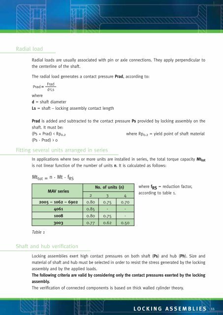
Radial loadRadial loads are usually associated with pin or axle connections. They apply perpendicular tothe centerline of the shaft.The radial load generates a contact pressure Prad, according to:FradPradd . Lswhered = shaft diameterLs = shaft – <strong>locking</strong> assembly contact lengthPrad is added and subtracted to the contact pressure Ps provided by <strong>locking</strong> assembly on theshaft. It must be:(Ps + Prad) < Rp 0.2where Rp 0.2 = yield point of shaft material(Ps - Prad) > 0Fitting several units arranged in seriesIn applications where two or more units are installed in series, the total torque capacity Mt totis not linear function of the number of units n. It is calculated as follows:Mt tot = n . Mt . f RSMAV seriesNo. of units (n)2 3 42005 – 1062 – 6902 0.80 0.75 0.704061 0.85 - -1008 0.80 0.75 -3003 0.77 0.62 0.50where f RS = reduction factor,according to table 1.Table 1Shaft and hub verificationLocking <strong>assemblies</strong> exert high contact pressures on both shaft (Ps) and hub (Ph). Size andmaterial of shaft and hub must be selected in order to resist the stress generated by the <strong>locking</strong>assembly and by the applied loads.The following criteria are valid by considering only the contact pressures exerted by the <strong>locking</strong>assembly.The verification of connected components is based on thick walled cylinder theory.LOCKING ASSEMBLIES 11