306WA - Analog trace oxygen analyzer - Teledyne Analytical ...
306WA - Analog trace oxygen analyzer - Teledyne Analytical ...
306WA - Analog trace oxygen analyzer - Teledyne Analytical ...

Create successful ePaper yourself
Turn your PDF publications into a flip-book with our unique Google optimized e-Paper software.
Model <strong>306WA</strong>5.4 Calibration ............................................................... 5-25.4.1 Internal Calibrator ........................................ 5-25.4.2 Standard (span) Gas Calibration ................. 5-25.5 Cell .......................................................................... 5-45.5.1 Electrolyte Replacement .............................. 5-45.5.2 Lead Electrode............................................. 5-55.6 Screen Assembly..................................................... 5-55.7 Calibrator ................................................................. 5-65.8 Reservoir and Humidifier Column ........................... 5-65.9 Leak Detection ........................................................ 5-85.9.1 Leak Detection Procedure ........................... 5-85.9.2 Cell Leak ...................................................... 5-9AppendixSpecifications ................................................................. A-1Spare Parts List .............................................................. A-2Drawing List .................................................................... A-3Calibration Data .............................................................. A-4ivTELEDYNE ELECTRONIC TECHNOLOGIES<strong>Analytical</strong> Instruments
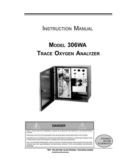
Trace Oxygen AnalyzyzerIntroduction 1.0IntroductionThe <strong>Teledyne</strong> <strong>Analytical</strong> Instruments Model <strong>306WA</strong> Trace OxygenAnalyzer is designed to detect <strong>trace</strong> concentrations of <strong>oxygen</strong> in processstreams. It utilizes <strong>Teledyne</strong>’s patented electrochemical sensor which requiresminimal maintenance and exhibits a 90% response in less than oneminute. Cell output is insensitive to flow rate changes within the operatingrange of the <strong>analyzer</strong>’s flowmeter.The Model <strong>306WA</strong> features a welded stainless sampling system forlong-term, leak-free operation.While the <strong>analyzer</strong> is offered in several configurations, they are virtuallyidentical with the exception of housing or options such as special meters. Forpurposes of clarity, this manual will discuss the unit in general, since differenceswill be minor and will be obvious to the user.1.1 Method of OperationGas from the process stream is fed through a sample line to the sampleinlet port of the <strong>analyzer</strong>. The sample is directed through the <strong>analyzer</strong>’ssample system, where <strong>oxygen</strong> concentration is detected by the sensor. Thesensor generates an output signal which is read out on a suitable recorder ormeter.The <strong>analyzer</strong> components include a throttle valve and flowmeter tocontrol sample flow, a humidifier to condition the sample, the measuring celland its associated circuitry, and a calibrator to adjust the sensitivity of the<strong>analyzer</strong> to the desired measurement range.1.2 Required EquipmentFor proper operation, the <strong>analyzer</strong> may require accessory equipment,particularly in the area of sample conditioning. The need for additionalequipment is dictated by the conditions of each application.TELEDYNE ELECTRONIC TECHNOLOGIES<strong>Analytical</strong> Instruments1-1
1.0 Introduction Model <strong>306WA</strong>1.2.1 Sample ConditioningThe sample should be free of entrained solids and condensable vapors,and be at a relatively constant pressure between 1 and 100 psig. However,more efficient operation is obtained with pressures in the range of 5 to 10psig. Pressure surges can carry fluid from the humidifier into the cell andimpair cell operation. Filters, scrubbers, or pressure regulators are oftennecessary, depending on local conditions.1. Filters. If filters are necessary, they should be convenientlylocated near the <strong>analyzer</strong>, and installed in a fashion which permitseasy removal for periodic cleaning or replacement.2. Scrubbers.If the sample contains small quantities of acidicanhydrides (SO 2, etc.) or mercaptans (H 2S, etc.) they will reactwith the electrolyte or the cathode, and for consistent operationshould be removed. A caustic scrubber is usually effective.3. Pressure regulators. While the <strong>analyzer</strong> will accept pressures to100 psig, a range of 5 to 10 psig is recommended. In addition,pressure surges can affect instrument operation. In either case, theuse of a pressure regulator is advisable. Install the regulator asclose to the sample point as possible to reduce sample travel timeto a minimium. The regulator should incorporate a metallicdiaphragm to prevent the diffusion of atmospheric <strong>oxygen</strong> intothe sample.1.2.2 Recorder /Meter ReadoutThe meter installed on the <strong>306WA</strong> is either analog or digital. Therecorder used for <strong>analyzer</strong> signal readout is usually of the self-balancingpotentiometric type. It should have an input inpedance of 20 ΚΩ or higherfor the 0 to 1 VDC (or optionally less than 0-1 VDC) signal output, and 4-20mADC isolated ground (standard) for maximum load resistance of 1.0 ΚΩ.1-2TELEDYNE ELECTRONIC TECHNOLOGIES<strong>Analytical</strong> Instruments
Trace Oxygen AnalyzyzerOperational Theory 2.0Operational Theory2.1 SensorThe sensor is an open-cathode cell, an electrochemical transducerspecific to <strong>oxygen</strong>. The cathode of the cell is composed of silver screenelements with a large surface area. The screen assembly is mounted in anacrylic block, with the lower edges of the screens immersed in potassiumhydroxide electrolyte. A thin layer of electrolyte is maintained on the surfacesof the screens by capillary action. A lead disk is positioned under thescreens and serves as the anode.The sample gas stream is passed directly over the cathode screens,initiating an electrochemical reaction. Four electrons are generated by theoxidation of the lead anode, and are then used to reduce <strong>oxygen</strong> at thecathode. The flow of electrons between the anode and cathode creates anelectric current which is directly proportional to the <strong>oxygen</strong> concentration inthe sample stream. In the absence of <strong>oxygen</strong>, no oxidation or reductiontakes place, and no current is produced.In simplified form, the reaction may be described as follows: <strong>oxygen</strong> isreduced at the cathode by the mechanism4e - +O 2+ 2H 2O → 4OH -This cathodic half-reaction occurs simultaneously with the anodic halfreactionPb + 2OH - → PbO + H 2O + 2e -The overall reaction isO 2+ 2Pb → 2PbO2.2 HumidifierIt is necessary to maintain a film of electrolyte on the screens of theelectrode assembly. This means that the humidity of the sample as it flowsthrough the cell must be such that the water vapor pressure of the electro-TELEDYNE ELECTRONIC TECHNOLOGIES<strong>Analytical</strong> Instruments2-1
2.0 Operational Theory Model <strong>306WA</strong>lyte is equal to the water vapor pressure in the sample gas. If the humidityof the sample is too low, water will evaporate from the electrolyte, dryingthe cell. If the sample humidity is too high, water will condense out into theelectrolyte, flooding the cell.The sample is humidified by bubbling it through water in the humidifiercolumn just before it enters the cell. The humidifier column is in the sameheated compartment as the cell and so is held at the same temperature. Thewater in the column, however, is cooled by evaporation into the sample gas.Thus, the sample gas will normally have a humidity that is too low forequilibrium with the cell. It is assumed here, of course, that since the cellcomponent is heated above ambient temperature, the sample gas is less thansaturated at the compartment temperature when it enters the <strong>analyzer</strong>.The humidity of the sample is increased to be in equilibrium with thecell electrolyte by heating the water in the humidifier column. The humidiferheater is in the base of the column, and the amount of heating is adjustedwith the humidity control that is located on the panel of the control unit.The amount of heating required depends on the sample flow rate, thesample humidity, and the specific heat of the sample. The correct adjustmentfor the operating conditions of any particular installation is obtained bychecking the cell electrolyte level periodically as described in section 4.2.3.The humidifier column also contains baffles to stop water from splashingup into the line to the sample cell at high flow rates.2.3 Flow SystemThe <strong>analyzer</strong> flow system is shown schematically in Figure 1. It includesa needle valve for adjusting the sample flow rate, a flowmeter toindicate the sample flow required for calibration, the humidifier, the calibrator,the measuring cell, and an automatic level control system for the waterin the humidifier.As can be seen from Figure 1, the sample enters the humidifier columnagainst the pressure of a water column from the base of the humidifier tothe water level in the reservoir, which is approximately 4 inches. Thisdetermines the minimum sample pressure at which any sample can flowthrough the <strong>analyzer</strong>. In practice, the sample pressure must be somewhatgreater than this in order to have an adequate flow rate.The automatic level control in the humidifier column is accomplishedby connecting the sample outflow from the cell to the bottom of the reservoir.The puts a back pressure on the sample in the cell and upper portion of2-2TELEDYNE ELECTRONIC TECHNOLOGIES<strong>Analytical</strong> Instruments
Trace Oxygen AnalyzyzerOperational Theory 2.0Figure 1: Flow System SchematicTELEDYNE ELECTRONIC TECHNOLOGIES<strong>Analytical</strong> Instruments2-3
Trace Oxygen AnalyzyzerOperational Theory 2.0Figure 2: Proper CalibrationTELEDYNE ELECTRONIC TECHNOLOGIES<strong>Analytical</strong> Instruments2-5
2.0 Operational Theory Model <strong>306WA</strong>The three ranges of the <strong>analyzer</strong> are intended primarily to make calibrationconvenient. It is expected that the <strong>oxygen</strong> content of the sample beinganalyzed will be within the narrow range (Range No. 1) of the <strong>analyzer</strong>.Then when the <strong>analyzer</strong> is switched to Range No. 2, a sufficiently largeamount of <strong>oxygen</strong> can be added by the calibrator to five a reliable calibration.Since the calibration is dependent on adjusting the change in indication,this change should be as large as possible—at least 50% of the widerrange.For example:Analyzer range: 0-1, 0-100, 0-1000Sample reading: 18 PPMCheck calibration:Adjust the <strong>analyzer</strong> calibration potentiometer so that 50 ppm of <strong>oxygen</strong>is being added to the sample. This is the change in actual <strong>oxygen</strong> content ofthe sample.Assume that the <strong>analyzer</strong> changes its output to read 52.The change in output indications is 52 - 18 = 34 when 50 PPM O 2isadded. Therefore, the span potentiometer should be adjusted to give areading of(18 x 50) + 50 = 76.5 PPM34NOTE: For details, see Appendix: Calibration Considerations.2-6TELEDYNE ELECTRONIC TECHNOLOGIES<strong>Analytical</strong> Instruments
Trace Oxygen AnalyzyzerInstallation 3.0Installation3.1 LocationWith proper shielding of the leads, the <strong>analyzer</strong> and the readout devicecan be separated by as much as 1,000 feet. However, they should be placedas close together as possible. For the most convenient operation, the readoutrecorder or meter should be within view of the controls, particularlywhen the unit is being calibrated. Other location considerations:1) The <strong>analyzer</strong> should be sheltered from the elements.2) Ambient temperature must be within 30 to 120 °F.3) The unit should not be subject to excessive shock or vibration.4) It should be as close as possible to the sample point.5) There must be access to the back and side of the unit forconnection or maintenance of sample lines and power.NOTE: Since the level of the electrolyte in the measuring cell is critical andthe water level control system for the humidifier is gravity sensitive,THE ANALYZER MUST BE MOUNTED SO THAT THE BOTTOM OFTHE CASE IS LEVEL.Figure 3 depicts a typical system layout.3.2 Electrical ConnectionsA diagram of the necessary electrical connections is shown in Figure 4.Note: See the Interconnection Diagram (drawing A-21916) included in theback of this manual, as well as any Addenda that may be includedwith this manual for information specific to your instrument.The connections include a terminal for grounding the <strong>analyzer</strong> case andchassis in accordance with accepted industrial practices. The maximumpower requirement is less than 1½ amperes at 115 VAC.TELEDYNE ELECTRONIC TECHNOLOGIE<strong>Analytical</strong> Instruments3-1
3.0 Installation Model <strong>306WA</strong>Figure 3: Typical System Layout3.3 Sample ConnectionsThe sample line is connected at the back of the <strong>analyzer</strong> case as depictedin Figure 5. Use care in assembling any part of the sampling systemto avoid leaks. Oxygen can diffuse into the system through small leaks evenwhen sample pressure is much greater than atmospheric pressure.1. Connectors.Use straight tube connectors where possible.This facilitates removal of the <strong>analyzer</strong> section from the caseduring maintenance or service.2. Lines. Lines should consist of metallic tubing, since <strong>oxygen</strong> candiffuse through plastic. Use continuous tubing where possible.3. Vent. The analyzed sample is vented through the back of theunit as shown in Figure 5.The <strong>analyzer</strong> should have a vent line of ¼" diameter tubing at least twofeet long, running downward from the vent connection. This is to preventair from diffusing into the reservoir and dissolving into the humidifier makeupwater.If it is not desirable to vent the sample into the atmosphere, a vent lineto carry the sample to a suitable venting area will be required. The sampleleaves the vent connection of the <strong>analyzer</strong> saturated with water vapor at atemperature somewhat above ambient, so a suitable trap to remove condensatewithout plugging the vent line will be required. The vent line shouldalso be arranged so that it cannot become plugged by dirt or dust.3-2TELEDYNE ELECTRONIC TECHNOLOGIES<strong>Analytical</strong> Instruments
Trace Oxygen AnalyzyzerInstallation 3.0Figure 4: General Connection DiagramSee the specific Interconnection Diagram for your instrument in the drawingpackage located at the back of the manual. See also any Addenda that may beincluded with this manual.TELEDYNE ELECTRONIC TECHNOLOGIE<strong>Analytical</strong> Instruments3-3
3.0 Installation Model <strong>306WA</strong>Figure 5: Gas Connections to Back of Analyzer3-4TELEDYNE ELECTRONIC TECHNOLOGIES<strong>Analytical</strong> Instruments
Trace Oxygen AnalyzyzerOperations 4.0Operations4.1 Filling the ReservoirThe reservoir is located on the right side of the <strong>analyzer</strong> case.1) Insure that the cap on the drain spout is securely tightened.2) Remove cap from fill port on top of reservoir.3) Pour distilled water into reservoir until it is half full (about onequart). The water will automatically flow into the humidifiercolumn.4) Replace cap on fill port and securely tighten. A missing or loosecap will permit the sample to vent into the <strong>analyzer</strong> case.4.2 Detector CellThe cell is located in the heated compartment on the left side of the<strong>analyzer</strong> case, as shown in Figure 6. To open the compartment, unscrew thecaptive knurled knobs at the top and bottom of the compartment and removethe plastic window.4.2.1 Cell PackagingThe cell is packaged separately from the <strong>analyzer</strong>. It is filled withdistilled water to prevent oxidation of the electrodes from exposure to theatmosphere. The cell should be left filled with the distilled water until the<strong>analyzer</strong> is installed and ready for operation. The cell should not be exposedto the atmosphere for any prolonged duration.4.2.2 ElectrolyteThe cell electrolyte is <strong>Teledyne</strong> Type A, used in applications wherethere is a complete absence of acidic anhydrides (CO 2, SO 2) in the samplegas. Type A electrolyte is a 10% solution (w/v) of reagent-grade potassiumhydroxide (KOH) in distilled water.TELEDYNE ELECTRONIC TECHNOLOGIES<strong>Analytical</strong> Instruments4-1
Trace Oxygen AnalyzyzerOperations 4.0Sufficient electrolyte is provided for initial servicing of the cell. Electrolytefor future service should be ordered from <strong>Teledyne</strong>. When ordering,specify type and quantity.4.2.3 Cell InstallationPrior to servicing and installing the cell, inspect the lead electrode inthe acrylic base for signs of oxidation, indicated by a reddish-brown oryellow discoloration. If discoloration is noted, clean the cell as directed insection 5.5.2 before placing it in service.WARNING: Type A electrolyte is caustic. Use extreme care inhandling. Protective equipment including but notlimited to gloves and safety glasses should be wornwhile handling electrolyte. Refer to the Material SafetyData Sheet in the Appendix regarding potential hazardsand corrective action in case of accident.1) Remove the four cell mounting bolts which secure the plasticcover. Pour out the distilled water.2) Pour about half the furnished electrolyte into the cell and sloshuntil all components within the cell are wetted by the solution.Drain and dispose of the solution.3) Wipe the top of the cell and the O-ring with a clean, disposabletissue to remove solution from the exterior. DO NOT touch theinterior of the cell.4) Carefully pour in electrolyte until it just touches the bottom edgeof the silver screen assembly at all points. This is indicated by adefinite wicking of electrolyte onto the screen assembly at everypoint along ithe bottom edge. It is essential at this point that thebottom edge of the screen assembly be wetted at all points (asseen by the wicking action), but not over-immersed (as large asurface area as possible of the screen assembly must remainabove the electrolyte, while every point of the bottom edge mustbe wetted).NOTE: The electrolyte level in the cell is critically related to its sensitivitydue to the change in the cathode surface area exposed to theeledctrolyte.5) Carefully place the cell under the cell mounting plate with theouter terminal toward the front. Secure in place with four boltssupplied with the cell. Refer to Figure 7.6) Connect the red lead to the center terminal and the black lead tothe outer terminal.TELEDYNE ELECTRONIC TECHNOLOGIES<strong>Analytical</strong> Instruments4-3
4.0 Operations Model <strong>306WA</strong>Figure 7: Cell Compartment Components4-4TELEDYNE ELECTRONIC TECHNOLOGIES<strong>Analytical</strong> Instruments
Trace Oxygen AnalyzyzerOperations 4.0NOTE: The silver screens in the cell have been specially treated to provideproper detection characteristics. They must be kept clean andMUST NOT be touched. Even clean fingers secrete natural oilswhich contaminate the screens. If the screens need straightening,wash a small pair of tweezers thoroughly to remove any grease,rinse them in distilled water, and use them to carefully bend thescreens back into place.4.3 CalibratorThe calibrator is located at the top of the humidifier column as shownin Figure 6. Also refer to Figure 8.1) Disconnect the electrical leads attached to the terminal posts.2) Remove the two screws adjacent to the terminal posts. Removethe assembly, being careful to avoid touching the calibrator wickagainst other surfaces.3) Dip the wick into fresh electrolyte solution and then shake toremove excess solution. Blot the end of the wick with anabsorbent tissue.WARNING: Type A electrolyte is caustic. Use extreme care inhandling. Protective equipment including but notlimited to gloves and safety glasses should be wornwhile handling electrolyte. Refer to the Material SafetyData Sheet in the Appendix regarding potential hazardsand corrective action in case of accident.4) Carefully slide the calibrator assembly back into the humidifierblock cavity and secure with two mounting screws. The screwsmust be turned down firmly to insure a leak-free O-ring sealbetween the assembly and the humidifier block.5) Reconnect the electrical leads to the terminal posts.CAUTION:The calibrator wick and electrodes must be kept cleanand must not be touched. Contamination will result incalibration errors.4.4 Throttle ValveThe throttle valve is located at the top of the reservoir tank. Refer toFigure 6.1) Gently turn the valve counterclockwise. A stream of bubblesshould appear at the base of the humidifier column, and the floatof the flowmeter should rise in its tube.TELEDYNE ELECTRONIC TECHNOLOGIES<strong>Analytical</strong> Instruments4-5
4.0 Operations Model <strong>306WA</strong>Figure 8: Calibrator Assembly4-6TELEDYNE ELECTRONIC TECHNOLOGIES<strong>Analytical</strong> Instruments
Trace Oxygen AnalyzyzerOperations 4.02) Adjust the valve so that the flowmeter float is centered in theflow rate reference indicator.CAUTION: Open the throttle valve carefully. Excessive flow ratemay cause water in the humidifier column to be carriedinto the detector cell. This can cause erratic readingsand may require disassembly, cleaning, and refilling ofthe sensor.3) The flowmeter indicator has been factory set to a flow rate of150 cc/min. for the specified sample gas.CAUTION:Excessive flow rate may cause water in the humidifierto be carried to the flowmeter causing moisture toaccumulate. This can cause the ball to stick in theflowmeter. To remove moisture, remove the flowmeterand allow to air or blow dry. Refer to the detailed instructionsin Figure 10 for removal and installation ofthe column.4.5 Humidity ControlThe humidity control is located on the front panel of the control unit,and is adjusted to maintain a constant electrolyte level in the detector cell.In effect, the control governs the humidity of the sample which is directedto the cell.1) At start-up, the humidity control knob should be set to 30. Notethe cell electrolyte level as a reference. Approximately 3/32" ofthe bottom edge of the screen assembly should be immersed inthe electrolyte.2) Operate the <strong>analyzer</strong> for 24 hours and compare the electrolytelevel with the “reference” established in Step 1. If the level islower than the reference, adjust the knob a few divisionsclockwise; if higher, adjust a few divisions counterclockwise.3) Operate another 24 hours and repeat Step 2.4) Continue adjustments at ever-increasing intervals until a constantelectrolyte level is attained in the cell.Once the <strong>analyzer</strong> is suitably located, all components serviced andinstalled, and sample and electrical connections made, the instrument isready for operation.TELEDYNE ELECTRONIC TECHNOLOGIES<strong>Analytical</strong> Instruments4-7
4.0 Operations Model <strong>306WA</strong>4.6 PowerWhen power is turned on, it is used to heat the cell compartment andto provide current to the calibrator. The cell operates without appliedpower, but its output will vary with changes in ambient temperature.4.7 Warm-Up and StabilizationWhen the <strong>analyzer</strong> is initially put into operation, the air in the lines andsample passages will drive the output indication to the top of the scale. Thetime required to sweep out this residual air may be several hours before anon-scale indication is reached. During this time the cell compartment isheating and reaching its controlled temperature.4.7.1 CalibrationThe <strong>analyzer</strong> is calibrated by adding a known amount of <strong>oxygen</strong> intothe sample stream. The sensitivity of the <strong>analyzer</strong> is adjusted until thechange indicated by the <strong>analyzer</strong> is equal to the amount of <strong>oxygen</strong> actuallyadded.1. Adjust the sample flow rate until the flowmeter float is centeredin the flowmeter reference indicator. Note the reading of theexternal recorder or meter.2. Turn the calibrator power switch to ON. Adjust the calibratorcurrent dial to read the amount of <strong>oxygen</strong> to be added. The dialreads 0 to 100 PPM O 2(See Appendix A4 for the O 2settings).3. Leave the power and current controls in the positions selectedabove. The calibrator current will continue to flow until thecalibrator power switch is turned OFF.4. If the external recorder/meter does not indicate the properamount of <strong>oxygen</strong> (sample reading plus added <strong>oxygen</strong>), adjustthe sensitivity control until it does.5. When the output reaches the proper equilibrium, turn thecalibrator power switch to OFF. The recorder/meter will movedownscale to indicate the <strong>oxygen</strong> content of the sample.If the output indication requires adjustment of more than 10%,the indicated <strong>oxygen</strong> content of the sample will differ noticeablyfrom the original indication. Repeat steps 2, 3, and 4, using thenew sample <strong>oxygen</strong> content value as a starting point.The above procedure should achieve the correct sensitivity settingthough a series of sucessive approximations.4-8TELEDYNE ELECTRONIC TECHNOLOGIES<strong>Analytical</strong> Instruments
Trace Oxygen AnalyzyzerMaintenance & Trouboubleshooting 5.0Maintenance & TrouboubleshootingAfter the <strong>analyzer</strong> has been put into operation and calibration has beenaccomplished, routine inspection will be required for normal operation.5.1 Flowmeter and HumidifierThe flowmeter and humidifier column must be checked daily to insureproper flow, and corrected as necessary. Refer to sections 2.2: Humidifierand 4.4: Throttle Valve.5.2 Cell Electrolyte LevelThe level of electrolyte in the cell must be checked daily and adjustedas necessary. Refer to section 4.2.3: Cell Installation.5.3 ReservoirThe water level in the reservoir should be checked at least every twoweeks. Follow this procedure:a) Remove the cap from the filler spout.b) Obtain a clean glass tube about 4 to 5 inches long and about ¼ "outer diameter.c) Lower the tube into the tank through the filler spout until ittouches bottom.d) Place a finger over the end of the tube, and withdraw the tubefrom the tank. The height of water in the tube is the heightof the water level in the tank.e) If the water level in the reservoir is below 1 ", add a quart ofdistilled water.f) Replace the filler spout cap securely after verifying that the O-ring seal is in good condition.TELEDYNE ELECTRONIC TECHNOLOGIES<strong>Analytical</strong> Instruments5-1
5.0 Maintenance & TrouboubleshootingModel <strong>306WA</strong>5.4 Calibration5.4.1 Internal CalibrationThe sensitivity of the unit should be checked at two to four weekintervals. Calibration procedures are described in section 2.4, 4.7.1 andappendix A4.5.4.2 Span Gas CalibrationThe 306 is designed for accuracy measurement. It has an internalcalibrator. The calibration process is stated in the section that follows, insection 4.7.1 and in appendix A4.- Span gas is not required.- Span gas is an option to calibrate 306 <strong>analyzer</strong>.- Span gas should be between 70-90% of the primary (working)range.NOTE:Refer to Section 4.3 for calibrator preparation prior calibration.5-2There are two connection methods that can be utilized for the sampleand span inputs:1. Three Way Valve Method- Install a three-way valve are as follows:- Connect a common port to the inlet of the <strong>analyzer</strong>.- Connect span gas bottle to the normally closed port.- Connect sample to the normally open port.- Turn on the sample gas.- Adjust the flow control inside the <strong>analyzer</strong> until the flow ball isinside the target (on the flow tube).- Purge the <strong>analyzer</strong> for 12 to 16 hours when the instrument isbeing installed for the first time or when replacing the cell.- Slowly switch the 3-way valve to the span gas.- Slowly adjust the span gas regulator until span gas flow is aboutthe same as the sample flow.- Wait until the reading is stabilized. Adjust span pot so that the<strong>analyzer</strong> is reading the same O2 concentration as indication on thespan gas bottle.- Now the <strong>analyzer</strong> is calibrated.- Switch the 3-way valve to sample and the instrument is ready togo online.TELEDYNE ELECTRONIC TECHNOLOGIES<strong>Analytical</strong> Instruments
Trace Oxygen AnalyzyzerMaintenance & Trouboubleshooting 5.0Figure 9: Cell AssemblyTELEDYNE ELECTRONIC TECHNOLOGIES<strong>Analytical</strong> Instruments5-3
5.0 Maintenance & TrouboubleshootingModel <strong>306WA</strong>2. Quick Disconnect Fitting MethodNOTE: Only stainless steel tubing must be connected to the quick discon-nect fitting.The steps are as follows:- Connect 1/4" tubing with the male quick disconnect fitting to theModel 306 sample inlet.- Turn on the sample gas.- Adjust the flow control inside the <strong>analyzer</strong> until the ball is inside thetarget (on the flow tube).- Purge the <strong>analyzer</strong> for 12 to 16 hours when the instrument is beinginstalled for the first time or when replacing the cell.- Remove the quick disconnect from sample inlet and connect it to thespan inlet.- Slowly adjust the span gas regulator until span gas flow is about thesame as the sample flow.- Wait until the reading is stabilized. Adjust span pot so that the<strong>analyzer</strong> is reading the same O 2concentration as indicated on thespan gas bottle.- Now the <strong>analyzer</strong> is calibrated.-Remove the quick disconnect from span inlet and connect it to thesample inlet and the instrument is ready to go online.5.5 CellThe electrochemical reaction in the analytical process results in theaccumulation of lead ions in the electrolyte, making the replacement of thelead electrode or the electrolyte necessary.5.5.1 Electrolyte Replacement<strong>Teledyne</strong> recommends that the electrolyte be replaced when foreignmaterial is accumulated in the cell or when the cell sensitivity is noticeabledecreased. This is typically identified when a large change is made to thespan pot setting during calibration. Remove the cell from is compartment,and drain, clean, rinse, and refill as described in section 4.2.3. After thecell is serviced or replaced, calibrate the <strong>analyzer</strong> as outlined in Section4.7.1: Calibration Using the Internal Calibrator.5-4TELEDYNE ELECTRONIC TECHNOLOGIES<strong>Analytical</strong> Instruments
Trace Oxygen AnalyzyzerMaintenance & Trouboubleshooting 5.05.5.2 Lead ElectrodeIf electrode is discolored when new, or has obviously deterioratedfrom use, it may be necessary to clean or replace the electrode. Use thefollowing procedure while referring to Figure 9.If the lead electrode is simply discolored, clean the entire cell accordingto the following procedure:a) Heat a quart of <strong>Teledyne</strong> cleaning solution to slightly below theboiling point, and completely fill the cell cavity with the heatedsolution.b) Let the solution stand for approximately five minutes. Drainand dispose of solution.c) Repeat steps a) and b).d) Rinse the cell with distilled water and then fill with electrolyte.Let stand for approximately two minutes and then drain anddispose of electrolyte.e) Refill the cell with electrolyte, immersing the lower edge of thesilver screens to about a 3/32 " depth.If the lead electrode is obviously beyond repair, it must be replaced.a) Remove the terminal nuts by removing them from the mountingscrews.b) Carefully remove the screw which holds the screen assembly inplace. Remove the screen assembly. Use clean tweezers and donot touch it with your fingers. Avoid any possiblecontamination of the screen.c) Cleanse the cell thoroughly in electrolyte solution.d) Insert the new lead electrode in place in the cell body andsecure with lock washers and screws.e) Carefully install screen assembly and secure with mountingscrew.f) Immerse the cell assembly in hot cleaning solution and thenrinse in distilled water.g) Install prepared cell assembly as described in section 4.2.3: CellInstallation.5.6 Screen AssemblyThe screen assembly will become discolored after prolonged use dueto contamination. When this occurs, and if the cell no longer displaysTELEDYNE ELECTRONIC TECHNOLOGIES<strong>Analytical</strong> Instruments5-5
5.0 Maintenance & TrouboubleshootingModel <strong>306WA</strong>adequate sensitivity, the entire cell assembly must be replaced. Refer tosection 4.2.3 for cell installation.5.7 CalibratorThe calibrator must be clean in order to operate properly. It should beremoved and inspected each time the cell is serviced. If, on inspection,dark deposits are seen on the calibrator wick, the calibrator should bereplaced. See section 4.3: Calibrator.The scrubber is not repairable. Once it has been determined that it isnot functioning correctly, it should be replaced. To determine if the scrubberis active or not:1. Allow sample gas with a few PPM of O 2into the sensor. Recordthe output registered on the meter2. Turn the scrubber on and allow zero gas into the sensor. Recordthe output.3. If the output in 1 and 2 are the same, the scrubber needs to bereplaced.5.8 Reservoir and Humidifier ColumnApproximately once each year the reservoir and humidifier columnshould be drained and cleaned. Use the following procedure:a) Reduce sample flow to approximately 50 cc/min.b) Refer to Figure 6. Place a small funnel with attached tubingbeneath the drain spout which is located on the underside of thereservoir. Remove the drain spout cap and allow the reservoirand humidifier column to drain thoroughly.c) Replace the drain spout cap, turn the sample flow off, andremove the fill cap on the top of the reservoir.d) Add a small amount of electrolyte to a pint of warm distilledwater. Pour the solution into the reservoir and replace the fillcap.e) Gently open the throttle valve and permit the sample to flow forfive to ten minutes.f) Reduce the sample flow to 50 cc/min. and drain the solutionfrom the reservoir. When drained, replace the drain cap andturn off the sample flow.g) Rinse by filling with distilled water and draining several times.5-6TELEDYNE ELECTRONIC TECHNOLOGIES<strong>Analytical</strong> Instruments
Trace Oxygen AnalyzyzerMaintenance & Trouboubleshooting 5.0h) If the humidifier column still retains deposits on its walls, itshould be removed and cleaned with a brush and suitablecleaner. See Figure 10. After cleaning, thoroughly rinse thecolumn in distilled water before reinstalling.NOTE: If electrolyte has severely etched the column, it should be replaced.i) After the reservoir and column have been cleaned, refill thereservoir as outlined in section 4.1: Filling the Reservoir.Removing the Humidifier Column:1) Remove the calibrator assembly from thetop humidifier block.2) Grasp the tube, and with a twistingmotion, work it up into the top humidifierblock until it clears the bottom blockcompletely.3) Angle the bottom of the tube towards youand twist it free of the top block.4) The top and bottom O-rings will remaincaptive in their blocks.To Reinstall:1) Engage the top of the tube in the topblock at an angle and twist up into thecalibrator cavity of the top block unit thebottom of the tube clears the bottom block.2) Swing the tube into line, and twist downinto the bottom block until the tube seats.3) Reinstall the calibrator assembly asdescribed in section 4.3.NOTE:The flowmeter is similarly constructedand can be removed and reinstalled following thesame procedure outlined above.Refer to the Spare Parts List in the Appendixfor replacement part numbers for theflowmeter column or humidifier column.TELEDYNE ELECTRONIC TECHNOLOGIES<strong>Analytical</strong> Instruments5-7
5.0 Maintenance & TrouboubleshootingModel <strong>306WA</strong>5.9 Leak DetectionThe most frequent cause of trouble in <strong>trace</strong> measurement is leakage.Tiny leaks which may be unnoticeable can cause serious errors in <strong>trace</strong>measurements. One of the principal problems is that air can diffuse into agas line through a small leak, even though the gas pressure in the line maygreatly exceed atmospheric pressure.When a leak occurs in a system where the mass flow velocity is lessthan the molecular velocity, gas molecules move in both directions throughthe leak. The net flow of a particular gas, e.g. <strong>oxygen</strong>, will depend on therelative partial pressure of that gas on each side of the leak. In a samplehaving only a few parts-per-million <strong>oxygen</strong>, there will be a net flow of<strong>oxygen</strong> inward unless the sample pressure is many thousands of pounds.5.9.1 Leak Detection ProcedureThe procedure outlined here is based on the premise that the leak rateis independent of sample flow rate.a) Stop the sample flow to permit <strong>oxygen</strong> to accumulate at thepoint of the leak.b) After approximately one minute, restart the sample flow. It isadvisable to practice establishing the flow rate to 150 cc/min.,the reference flow indication on the flowmeter, with one quickturn of the throttle valve.c) Simultaneous to restarting the flow, start a stopwatch tomeasure the time required for the recorder/meter to respond tothe accumulated <strong>oxygen</strong>.d) The following are approximate times for the accumulated<strong>oxygen</strong> to reach the cell from various points in the sample paththrough the <strong>analyzer</strong> at 150 cc/min.1.5 to 2 seconds Calibrator3.5 to 3.75 seconds Base of humidifier column*5.5 seconds Flowmeter6.5 seconds Metering valve7.5 seconds Gas connection at rear of <strong>analyzer</strong>> than 7.5 seconds Sample connection lines leading to<strong>analyzer</strong>* A leak at this location may indicate a leak in the column or inthe reservoir system.5-8TELEDYNE ELECTRONIC TECHNOLOGIES<strong>Analytical</strong> Instruments
Trace Oxygen AnalyzyzerMaintenance & Trouboubleshooting 5.05.9.2 Cell LeakIf there is no rise in <strong>oxygen</strong> reading when the sample flow is restartedin step 5.9.1.b, the measuring cell should be checked for leaks. The twomost likely leaks locations are at the two terminal seal O-rings, or at thelarge O-ring in the cell block mounting base.Check that the terminals are screwed tightly into place. Frequently,when a leak occurs at a terminal connection, a greenish crystalline depositwill be found inside the cell around the terminal mounting screw. This islead carbonate, which is formed by carbon dioxide in the air reacting withlead ions in the electrolyte.If the large O-ring at the mounting plate is leaking, the <strong>oxygen</strong> indicationwill begin rising almost immediately after the sample flow is stopped. Itwill continue to rise until sample flow is restarted, at which time it willbegin to gradually decrease.TELEDYNE ELECTRONIC TECHNOLOGIES<strong>Analytical</strong> Instruments5-9
5.0 Maintenance & TrouboubleshootingModel <strong>306WA</strong>SymptomNo <strong>analyzer</strong> response to<strong>oxygen</strong>.Cell lacks sensitivity.a) Poor electrical connection,or F1 fuse (a standard 2amp Slo-Blo fuse) hasblown.b) Cell electrolyte level toolow.c) Dirty cell.Caused) Short between cell cathodeand anode (the screen tolead–the base material–isshorted.)e) If d) above corrects theproblem, the cell hasprobably been poisoned,probably by fluid flowing intothe cell humidifier column.f) Cell has been poisoned by acomponent in the sample.a) Cell electrolyte level toolow, due to misadjusted orfaulty humidity control.b) Cell electrolyte too high,due to misadjusted or faultyhumidity control.c) Faulty humidity control.What To Doa) Verify proper connectionfrom the cell through thecontrol unit to the externalrecorder or meter; check forblown fuse. Replace asnecessary.b) Inspect electrolyte level andadd as necessary. Seesection 4.2.3, item 4.c) Remove cell and cleanthoroughly. See section4.2.3.d) Correct short. Refill withfresh electrolyte as needed.e) Check for excessive flowrate.Check for excessive foamingin the humidifier column.Drain and clean reservoir asnecessary. Refer to section5.8.f) If there has been no changein the normal samplecomposition, a scrubbermay be required to removethe offending component.a) Add electrolyte as necessary.Adjust humiditycontrol. See section 4.5.b) Drain electrolyte and refill.Adjust humidity control. Seesection 4.5.c) • Shut off main power.• Disconnect orange wirefrom TS5 terminal 5,place a voltmeter (set toAC current, range 0–100mA) in series with TS5-5and the disconnectedorange wire.CAUTION: High voltage ACpresent.5-10TELEDYNE ELECTRONIC TECHNOLOGIES<strong>Analytical</strong> Instruments
Trace Oxygen AnalyzyzerMaintenance & Trouboubleshooting 5.0SymptomCell lacks sensitivity (continued.)CauseFaulty humidity control (continued.)What To Do• Turn humidifier controlcompletely counterclockwise.• Turn on main power.• While watching thevoltmeter, turn thehumidifier control clockwise;the meter readingshould go from 0–50milliamps. If not, replacethe humidifier heaterelement or the humidifierheater control. To determinewhich should bereplaced, see paragraphbelow.If there is no current, eitherthe humidifier element orcontrol is defective. Todetermine which it is:• Turn the humidifier controlknob fully ccw.• Disconnect the voltmeterfrom TS5-5 and orangewire.• Change the voltmeterfunction to 200V AC.• Place the voltmeteracross TS5-5 and TS5-4.• Watching the meter, turnthe humidifier controlknob cw and watch thevoltmeter read from 0 to120V AC (0-220V for220VAC Application).• If not, replace R2 (behindthe control knob); seeparagraph below.• If there is voltage, replacethe heater element; seeparagraph below.TELEDYNE ELECTRONIC TECHNOLOGIES<strong>Analytical</strong> Instruments5-11
5.0 Maintenance & TrouboubleshootingModel <strong>306WA</strong>SymptomCell lacks sensitivity (continued.)CauseFaulty humidity control(continued.)d) Cell compartment not atproper temperature(104 °F).e) Faulty triac temperaturecontrol circuit.What To DoTo replace humidifiercontrol:• Shut off all power andremove the AC powercord from the powersource.• Refer to upper right-handcorner of the control unit.Remove the wiring andcontrols. Replace R2 withappropriate part, P/N P31(115VAC), P/N R1212(220VAC).To replace humidifierheater element:• Shut off all power andremove the AC powercord from the powersource.• Refer to left-hand side,bottom of the cell compartment.• Using Allen wrench size5/64 to remove Allenscrew from the bottom ofthe humidifier column; pullout the heater element,and unsolder the wires.• Replace with new heaterelement (P/N R991 for115VAC or P/N R1211 for220VAC) Solder wires,and replace heaterelement.d) Verify that the power switchis ON.Check condition of 2A fuse.e) • Turn off the power.Remove the power fromthe power source, unplugthe temperature controlboard. Remove the cellcompartment cover. Referto Interconnection diagram.• Connect voltmeter (set torange 20k ohm) toterminals 1 and 2 ofterminal strip TS4.5-12TELEDYNE ELECTRONIC TECHNOLOGIES<strong>Analytical</strong> Instruments
Trace Oxygen AnalyzyzerMaintenance & Trouboubleshooting 5.0SymptomCell lacks sensitivity (continued.)Calibrator slow to respond toadded <strong>oxygen</strong>.Calibrator shows no indication.CauseFaulty triac temperature control(continued.)a) Calibrator wick needswetting.a) Lack of power, poor connection,or dry wick.What To Do• The DMM should read230 to 250 ohms(115VAC) 500 to 700ohms (220VAC). MoveDMM to TS4 # 4&5. TheDMM should read between7,000 to 10,000ohms. If above test isOK, replace the temperaturecontrol P.C. Board• If none of the aboveimprove the sensitivity,replace the cell.a) Disassemble calibrator andmoisten the wick. Seesection 4.3: Calibrator.a) Verify that the main powerand calibrated powerswitches are ON.b) Check connectors tocalibrator.c) Check for dry wick.• Measure the voltagebetween terminals 6 and7 on terminal strip TS5.• With calibrator energized,the voltage drop acrossthe calibrator electrodes is1 to 3 V. However, a drywick will cause voltagesas high as 25 volts.d) Disassemble calibrator andmoisten the wick. Seesection 4.3.TELEDYNE ELECTRONIC TECHNOLOGIES<strong>Analytical</strong> Instruments5-13
5.0 Maintenance & TrouboubleshootingModel <strong>306WA</strong>Symptom CauseWhat To DoCalibrator current is erratic.Proper calibration current exists,but there is no cell response.a) Poor electrical connections.a) Short circuit in calibrator.a) Check for properconnections betweenthe control unit andcalibrator on terminalstrip TS5.b) Ensure that brown (13)and yellow (14) wiresconnect to brown andyellow posts respectivelyon calibratorassembly in the cellcompartment.c) Moisten wick. Seesection 4.3.a) Verify cell response to<strong>oxygen</strong> by loosening thecalibrator assembly tointroduce air, and thenbolt back in place.Recorder/meter shouldshow increase.b) If there is no response,inspect the calibrator forobvious shorts. If noteasily repairable,replace the calibrator.5-14TELEDYNE ELECTRONIC TECHNOLOGIES<strong>Analytical</strong> Instruments
Trace Oxygen AnalyzyzerAppendixAppendixSpecificationsRanges:Sensitivity:Accuracy:Response Time:System Operating Temperature:Sensor Type:Signal Output:Sample Requirement:Power Requirement:Alarm Output:Calibrator:0-1, 0-10, 0-100 ppm (optional highrange to 1000 ppm, optional low rangeto 500 ppb).0.5% of Full Scale.+2% of Full Scale at constant temperatureand pressure (temperature andpressure of calibration {for ranges 10ppm and above}). For ranges 1 ppmand below, Instrument Accuracy musttake into account Sensor Offset Errorwhich has been experimentally determinedto be 30 ppb.+5% of Full Scale over operatingtemperature (once temperature equilibriumhas been achieved)90% in less than 1 minute (for changesin the lowest range).5 °C to 50 °C.Electrochemical "Flower Cell".0-1V DC (4-20mA DC optional)Flow: 150 cc/min (Specified flowrate is required only during calibration).Pressure: 1 to 150 psig.Temperature: 15 °C to 38 °C115 VAC, 50/60 Hz (220 optional)2 alarms optional.Electrolytic Faradic Calibrator.TELEDYNE ELECTRONIC TECHNOLOGIES<strong>Analytical</strong> InstrumentsA-1
AppendixModel <strong>306WA</strong>Spare Parts ListQTY. PART NO. DESCRIPTION1 C1372 Cell assemblyNOTE: Specify cell class and range of <strong>analyzer</strong> when ordering.2 O5 O-ring, cell terminal1 O25 O-ring, cell seal2 O26 O-ring, calibrator2 O9 O-ring, humidifier column2 O8 O-ring, reservoir cap2 O204 O-ring, flowmeter1 A4616 Calibrator assembly1 A33748 Thermistor assembly1 A3042 Humidifier column assembly1 R2454 Humidifier column heater (110V)1* R2453 Humidifier column heater (220V)1 A5267 Reservoir cap5 F10 Fuse, 3AG-2A5 F6 Fuse, 3AG-1/4A, Slo-Blo2 H2 Heater (<strong>306WA</strong>)2 H68 Heater (307WA, 308WA)1 B6274 Flowmeter ass’y (specify background gas)1 C14449 PC Board, Proportional temp. control(For applications less than 10 PPM)1* C41274 PC Board, Proportional temp. control (220V)1* B29600 PC Board, E/I converter, isolated (O option)1* B14702 PC Board, E/I converter, neg. gnd. (I option)1* A9309 PC Board, Alarm comparator, dual (-2 opt.)1 A44608 Type A Electrolyte1 A44609 Type C Electrolyte1 A50510 Cal Kit (Eelectrolyte for calibrator)1 P31 Rheostat (Humidity Control Resistor) -1.5k, 115V1 R1212 Rheostat (Humidity Control Resistor) -5.0k, 220V* optionalA minimum charge is applicable to spare parts orders.IMPORTANT: Orders for replacement parts should include the model number,serial number, and range of the <strong>analyzer</strong> for which the parts areintended.A-2TELEDYNE ELECTRONIC TECHNOLOGIES<strong>Analytical</strong> Instruments
Trace Oxygen AnalyzyzerAppendixSEND ORDERS TO:TELEDYNE ANALYTICAL INSTRUMENTS16830 CHESTNUT STREETCITY OF INDUSTRY, CALIF. 91749TELEPHONE: (888) 789-8168(626) 934-1500(626) 961-9221FAX: (626) 961-2538(626) 934-1651TECHNICAL SUPPORT: (626) 934-1673WEB:www.teledyne-ai.comor your local representativeDrawing List<strong>306WA</strong>A-5855 Outline diagramA-21916 Interconnection diagramA-8704 Piping schematicD-41307 Schematic diagramD-43645 Wiring diagram307WAB-19026 Outline diagramB-20282 Interconnection diagramA-8704 Piping schematicD-19722 Schematic diagramD-29555 Wiring diagram308WAB-3370 Outline diagramB-6437 Interconnection diagramA-8704 Piping schematicB-6428 Schematic diagramA-6423 Wiring diagramTELEDYNE ELECTRONIC TECHNOLOGIES<strong>Analytical</strong> InstrumentsA-3
AppendixModel <strong>306WA</strong>Calibration DataRangeThe ranges of this <strong>analyzer</strong> are:Range Switch Position No. 1 PPM O 2Range Switch Position No. 2 PPM O 2Range Switch Position No. 3 PPM O 2Output SignalThe output signal is D.C.Background GasThis <strong>analyzer</strong> is intended to measure <strong>oxygen</strong> in a background of:The flowmeter has been set to indicate a flow of 150 cc/min. of this gas.If any other type of gas is to be analyzed, the flowmeter must be reset for thatgas, using a displacement type flowmeter, when the flow is set to 150 cc/min.Calibration TableYour calibrator will generate 0-100 ppm of <strong>oxygen</strong>.To set calibrator: Turn calibrator switch to ON position; turn calibrator dialto read amount of <strong>oxygen</strong> to be added.Calibration Current (mA)To add: 10 ppm set calibrator dial to read 100 .420 ppm set calibrator dial to read 200 .830 ppm set calibrator dial to read 300 1.240 ppm set calibrator dial to read 400 1.650 ppm set calibrator dial to read 500 2.060 ppm set calibrator dial to read 600 2.470 ppm set calibrator dial to read 700 2.880 ppm set calibrator dial to read 800 3.290 ppm set calibrator dial to read 900 3.6100 ppm set calibrator dial to read 1000 4.0Cell Class:Electrolyte TypeType A: 10% potassium hydroxide in distilled waterType B: 10% potassium carbonate in distilled waterType C: 20% potassium bicarbonate in distilled waterA-4TELEDYNE ELECTRONIC TECHNOLOGIES<strong>Analytical</strong> Instruments
Trace Oxygen AnalyzyzerAppendixCalibration ConsiderationsIn order to calibrate the Model 366, all that is required is to center thefloat of the flow tube in the target, add a known quantity of <strong>oxygen</strong> (0–100PPM) to the sample gas and adjust the span according to the example onpage 2.4. It should not be necessary to compensate for changes in altitude orambient temperature.The flow tube is a mass flow device and therefore automatically compensatesfor altitude changes should the instrument be moved to a higherelevation (in this instance a higher span setting will be required since thesensing element is sensitive to the partial pressure of <strong>oxygen</strong>).The ambient temperature does not affect the flow rate through the<strong>analyzer</strong> since the flow tube is located in the same temperature controlledcompartment as the cell assembly.Furthermore, it should be noted that the only time the flow rate iscritical is when calibration is being accomplished using the internal calibrator.When span gases are used and when sample gas is being analyzed theflow can vary ±10–20% and more without changing the reading. It is best,however, to keep the sample flow so that the float in the flow tube is at ornear the center of the target. Otherwise, a different humidifier setting may berequired.If positioning the float in the center of the target is in error by plus orminus one-quarter of the float’s diameter, an error of approximately ±1.5%of reading * will be produced.There are instances when it will be necessary to reset or check the exitflow of sample gas and set or reset the position of the target on the flow tube:• When a different background gas is being analyzed.• When the target has been accidently repositioned on the flow tube.The vent flow should be measured either with a volume displacementflow device (e.g. a “bubble-o-meter”) or a calibrated rotometer with correctionfactors for ambient temperature and pressure, and sample gas densityand viscosity. When using a volume displacement flow device it will benecessary to correct the 150 cc/min flow rate for ambient temperature andpressure. It will also be necessary, using either type of flow measuringdevice, to compensate for the increase in flowrate due to humidifying thesample gas. (The flow tube inside the <strong>analyzer</strong> is measuring the dry gasflowrate.)*If the actual <strong>oxygen</strong> concentration were, for example, 8.0 ppm, theresultant reading would be 7.9 (float high) or 8.1 (float low).TELEDYNE ELECTRONIC TECHNOLOGIES<strong>Analytical</strong> InstrumentsA-5
AppendixModel <strong>306WA</strong>To determine the corrected vent flow rate it will be necessary to knowthe ambient temperature (in °K), the ambient pressure (in mm Hg) and thevapor pressure of water at ambient temperature.Ambient temperature can be measured in °Centigrade or °F and convertedto °K.Degrees C = 5 (°F -32)9Degrees K = °C + 273Ambient pressure can be measured with an accurate barometer.or by knowing the altitudeP (mm Hg) = P(in Hg) x 76030.00P(mm-Hg) = 760 - (2.50 per 100 ft. of altitude)*The vapor pressure of water at ambient temperature can be obtainedfrom Table 1 on page A.8.To determine the corrected flow (F corrected), substitute the ambient temperature,pressure and vapor pressure of water in the following formula:F corrected=150 cc/min x T X 760 mm-Hg X (P+Pwater)294 °K** P PWhere:T = ambient temperature (in °K)P = ambient pressure (in mm Hg)P water= vapor pressure of water at ambient temp. (in mm Hg)By way of example, suppose that the target’s position on the flow tubeis in question and it has been determined that the ambient temperature is 77°F and the altitude where the instrument is being used is 5000 ft. above sealevel.Ambient Temp: °K = 5(77–32) + 273 = 298 °K9* This approximation is within ±0.5% of the ICAO Standard Atmosphereover the range 0-7500 ft. above sea level. Ref: “Fluid Mechanics forEngineering Technology” by Irving Granet, Prentice Hall, pp 83–84.**Reference ambient temperature : 294 °K (21 °C) was the ambienttemperature used in the Faradaic calculations.A-6TELEDYNE ELECTRONIC TECHNOLOGIES<strong>Analytical</strong> Instruments
Trace Oxygen AnalyzyzerAppendixAmbient Pressure: P(mm-Hg) = 760–(2.50 x 50) = 635 mm HgVapor Pressure of Water (at 298 °K): 23.9 mm HgCorrected Flow: F corr=150 x 298 x 760 x (635+23.9) = 189 cc/min294 635 635From the above computations, the exit flow rate should be set to 189 cc/min. using an appropriate flow measuring device and the target respositionedif necessary so that the float is centered within the target opening.Subsequently, it should not be necessary to measure the exit flow unlessanother circumstance, of the type listed above, occurs.Table 1:Vapor Pressure of Water(From 288–308°K)TELEDYNE ELECTRONIC TECHNOLOGIES<strong>Analytical</strong> InstrumentsA-7
AppendixModel <strong>306WA</strong>Ambient Temperature (°K)Vapor Pressure of Water (mm Hg)288 12.9289 13.7290 14.6291 15.6292 16.6293 17.7294 18.8295 20.0296 21.2297 23.9298 23.9299 25.4300 26.9301 28.6302 30.7303 32.1304 34.0305 35.9306 38.0307 40.2308 42.5NOTE:The MSDS on this material is available upon requestthrough the <strong>Teledyne</strong> Environmental, Health andSafety Coordinator. Contact at (626) 934-1592A-8TELEDYNE ELECTRONIC TECHNOLOGIES<strong>Analytical</strong> Instruments