Model 7600 - Teledyne Analytical Instruments
Model 7600 - Teledyne Analytical Instruments
Model 7600 - Teledyne Analytical Instruments

You also want an ePaper? Increase the reach of your titles
YUMPU automatically turns print PDFs into web optimized ePapers that Google loves.
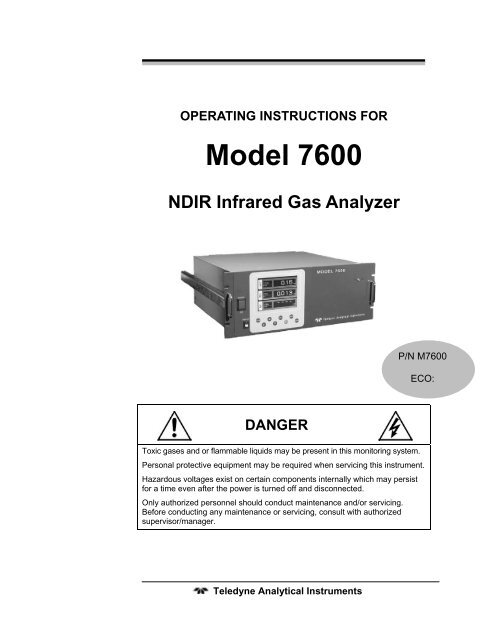
OPERATING INSTRUCTIONS FOR<strong>Model</strong> <strong>7600</strong>NDIR Infrared Gas AnalyzerP/N M<strong>7600</strong>ECO:DANGERToxic gases and or flammable liquids may be present in this monitoring system.Personal protective equipment may be required when servicing this instrument.Hazardous voltages exist on certain components internally which may persistfor a time even after the power is turned off and disconnected.Only authorized personnel should conduct maintenance and/or servicing.Before conducting any maintenance or servicing, consult with authorizedsupervisor/manager.<strong>Teledyne</strong> <strong>Analytical</strong> <strong>Instruments</strong>
<strong>Model</strong> <strong>7600</strong>Safety MessagesYour safety and the safety of others is very important. We haveprovided many important safety messages in this manual. Please readthese messages carefully.A safety message alerts you to potential hazards that could hurt youor others. Each safety message is associated with a safety alert symbol.These symbols are found in the manual and inside the instrument. Thedefinition of these symbols is described below:GENERAL WARNING/CAUTION: Refer to the instructionsfor details on the specific danger. These cautions warn ofspecific procedures which if not followed could cause bodilyInjury and/or damage the instrument.CAUTION: HOT SURFACE WARNING: This warning isspecific to heated components within the instrument. Failureto heed the warning could result in serious burns to skin andunderlying tissue.WARNING: ELECTRICAL SHOCK HAZARD: Dangerousvoltages appear within this instrument. This warning isspecific to an electrical hazard existing at or nearby thecomponent or procedure under discussion. Failure to heed thiswarning could result in injury and/or death fromelectrocution.Technician Symbol: All operations marked with this symbolare to be performed by qualified maintenance personnel only.NoSymbolNOTE: Additional information and comments regarding aspecific component or procedure are highlighted in the formof a note.CAUTION:THE ANALYZER SHOULD ONLY BE USED FOR THEPURPOSE AND IN THE MANNER DESCRIBED INTHIS MANUAL.<strong>Teledyne</strong> <strong>Analytical</strong> <strong>Instruments</strong>iv
Infrared Gas AnalyzerIF YOU USE THE ANALYZER IN A MANNER OTHERTHAN THAT FOR WHICH IT WAS INTENDED,UNPREDICTABLE BEHAVIOR COULD RESULTPOSSIBLY ACCOMPANIED WITH HAZARDOUSCONSEQUENCES.This manual provides information designed to guide you throughthe installation, calibration operation and maintenance of your newanalyzer. Please read this manual and keep it available.Occasionally, some instruments are customized for a particularapplication or features and/or options added per customer requests.Please check the front of this manual for any additional information inthe form of an Addendum which discusses specific information,procedures, cautions and warnings that may be peculiar to yourinstrument.Manuals do get lost. Additional manuals can be obtained fromTI/AI at the address given in the Appendix. Some of our manuals areavailable in electronic form via the internet. Please visit our website at:www.teledyne-ai.com.<strong>Teledyne</strong> <strong>Analytical</strong> <strong>Instruments</strong>v
<strong>Model</strong> <strong>7600</strong>Table of ContentsList of Figures ............................................................................... xList of Tables ............................................................................... xiiIntroduction ................................................................................. 151.1 Overview 151.2 Main Features of the Analyzer 151.3 Options Available 171.4 Applications 171.5 Description of the Main Unit 18Installation ................................................................................... 212.1 Unpacking the Analyzer 212.2 Choosing a Location 222.3 Mounting the Analyzer 232.4 Mounting the Input/Output Terminal Module 232.5 Gas Connections 252.5.1 Internal Piping Diagram 252.5.2 External Piping Diagram 272.5.3 Gas Conditioning 282.5.4 Flowrate 292.5.5 Preparation of Calibration Gas 292.5.6 Purging the Analyzer 302.5.7 Sample Gas Pressure 302.5.8 Example configuration of gas sampling system 302.6 Electrical Connections 322.6.1 Power Inlet 322.6.2 Input/Output Terminal Module 332.7 Testing the System 34<strong>Teledyne</strong> <strong>Analytical</strong> <strong>Instruments</strong>vi
Infrared Gas AnalyzerOperation ..................................................................................... 353.1 General Information 353.2 Display and Available Menus 363.3 The Display Screen 383.3.1 Measurement Mode 383.3.2 Setting/Selection Screen 403.4 Basic Operation 413.5 Setting Up the Analyzer in the User Mode 423.5.1 Switch Ranges 423.5.1.1 Manual Range Switching 433.5.1.2 Range identification contact operation 443.5.1.3 Remote Range Selection 453.5.1.4 Autoranging 463.5.2 Calibration Parameters 463.5.2.1 Calibration Value 463.5.2.2 Setting of Manual Zero Calibration 483.5.2.3 Setting of calibration range 503.5.2.4 Setting of auto calibration component/range 513.5.3 Alarm Setting 533.5.3.1 Configuring the Alarms 553.5.3.2 Hysteresis Setting 563.5.4 Setting of Auto Calibration 583.5.4.1 Auto Calibration 583.5.4.2 Gas Flow Time Setting 593.5.4.3 Cycle Setting Range 603.5.4.4 Remote Start 623.5.4.5 Forced Run/Stop of Auto Calibration 623.5.5 Setting of Auto Zero Calibration 653.5.5.1 Auto Zero Calibration 653.5.5.2 Forced run/stop of auto zero calibration 683.5.6 Peak Alarm Setting 703.5.7 Parameter Setting 73<strong>Teledyne</strong> <strong>Analytical</strong> <strong>Instruments</strong>vii
Infrared Gas AnalyzerA.3 Optional Functions 115A.4 Performance: 116A.5 Standard Requirements for Sample Gas 117A.6 Installation Requirements 118A.7 EC Directive Compliance 118A.8 Terminal Block Connections 119A.9 Description on Terminal Block 120Index........................................................................................... 125<strong>Teledyne</strong> <strong>Analytical</strong> <strong>Instruments</strong>ix
<strong>Model</strong> <strong>7600</strong>List of FiguresFigure 1-1: <strong>Model</strong> <strong>7600</strong>A Infrared Gas Analyzer ........................... 16Figure 1-2: <strong>Model</strong> <strong>7600</strong> Description .............................................. 19Figure 2-1: Slide Rail Mounting Dimensions ................................. 23Figure 2-2: Input/Output Terminal Module..................................... 24Figure 2-3: Mounting the I/O Module............................................. 24Figure 2-4: Internal Piping with Single or Dual Measuring Units ... 26Figure 2-5: External Piping with Single Inlet and Outlet ................ 27Figure 2-6: External Piping with Two Pair of Inlet/Outlet (1).......... 28Figure 2-7: External Piping with Two Pair of Inlet/Outlet (2).......... 28Figure 2-8: Five Component Analysis System .............................. 31Figure 2-9: <strong>Model</strong> <strong>7600</strong> Electrical Connections............................. 32Figure 2-10: Noise Suppression.................................................... 33Figure 2-11: I/O Cable Connection................................................ 33Figure 3-1: Front Panel of the <strong>Model</strong> <strong>7600</strong>.................................... 35Figure 3-2: Interface Keys on the Front Panel............................... 35Figure 3-3: Display Modes and Menu Hierarchy ........................... 37Figure 3-4: Example Screen—5 Component Analysis 12Channels................................................................................ 38Figure 3-5: Setting/Selection Screen Areas .................................. 41Figure 3-6: Hysteresis Example for a High Limit Alarm................. 57Figure 3-7: Example Auto Calibration ........................................... 61Figure 3-8: Example Auto Zero Calibration ................................... 67Figure 3-9: Peak Alarm Example .................................................. 72Figure 3-10: Output Hold for Manual Calibration........................... 75<strong>Teledyne</strong> <strong>Analytical</strong> <strong>Instruments</strong>x
Infrared Gas AnalyzerFigure 3-11: Output Hold for Auto Calibration ............................... 76Figure 3-12: Output Hold for External Hold ................................... 76Figure 3-13: Average Value Reset ................................................ 79Figure 3-14: Example Average Period .......................................... 80Figure 4-1: Top Cover Removal .................................................... 95Figure 4-2: Sample Cell Removal.................................................. 95Figure 4-3: Sample Cell................................................................. 96Figure 4-4: IR Window Assembly .................................................. 97Figure 4-5: Detector Secure Nut.................................................... 98Figure 4-6: Cell Block Assembly.................................................... 99Figure 4-7: Optical Adjustment Display for Dual Optical SystemOption................................................................................... 100Figure 4-8: Optical Zero Adjustment............................................ 101Figure 4-9: Beam Adjustment Plate............................................. 102Figure 4-10: Bubbler Apparatus .................................................. 103Figure 4-11: The Error Log Screen.............................................. 107<strong>Teledyne</strong> <strong>Analytical</strong> <strong>Instruments</strong>xi
<strong>Model</strong> <strong>7600</strong>List of TablesTable 2-1: Correspondence of Measured Components andMeasuring Units ..................................................................... 27Table 2-2: Zero and Span Gas...................................................... 29Table 4.1 Troubleshooting and Maintenance ................................ 93Table 4-2: Components of Optical Adjustment Screen ............... 100Table 4-3: Error Messages.......................................................... 104<strong>Teledyne</strong> <strong>Analytical</strong> <strong>Instruments</strong>xii
Infrared Gas AnalyzerDANGERCOMBUSTIBLE GAS USAGEWARNINGThis is a general purpose instrument designed for use in anon-hazardous area. It is the customer's responsibility toensure safety especially when combustible gases are beinganalyzed since the potential of gas leaks always exist.The customer should ensure that the principles of operatingthis equipment are well understood by the user. Misuse ofthis product in any manner, tampering with its components,or unauthorized substitution of any component mayadversely affect the safety of this instrument.Since the use of this instrument is beyond the control of<strong>Teledyne</strong> <strong>Instruments</strong>/ <strong>Analytical</strong> <strong>Instruments</strong>, referred asTI/AI, no responsibility by TI/AI, its affiliates, and agents fordamage or injury from misuse or neglect of this equipment isimplied or assumed.<strong>Teledyne</strong> <strong>Analytical</strong> <strong>Instruments</strong>xiii
<strong>Model</strong> <strong>7600</strong><strong>Teledyne</strong> <strong>Analytical</strong> <strong>Instruments</strong>xiv
Infrared Gas AnalyzerIntroductionIntroduction1.1 OverviewThe <strong>Model</strong> <strong>7600</strong> Infrared Gas Analyzer is a microprocessor basedinfrared gas analyzer used to measure the concentration of NO, SO 2 ,CO 2 , CO and CH 4 contained in sample gas. It is based on the principlethat different molecular species have unique absorption spectrum in theinfrared, and the intensity of absorption is determined by the Lambert-Beer law.In addition to the infrared analyzer, the <strong>Model</strong> <strong>7600</strong> can also beequipped with a built-in compact paramagnetic O 2 sensor or employ anexternal zirconia oxygen sensor to increase to 5 the number ofsimultaneous component species the unit can analyze.<strong>Teledyne</strong>'s Series <strong>7600</strong> Infrared (IR) Gas Analyzer is convenientlypackaged in either a 19" rack mount or NEMA-4 wall mount enclosure.The NEMA-4 enclosure can be X or Z-purged to satisfy hazardous areainstallation requirements.A high-sensitivity mass flow type twin detector is used for infraredmeasurements. By utilizing a single beam, double path design inconjunction with a serial dual-layer transmission detector, the Series<strong>7600</strong> delivers long term, drift-free performance.The concentration of the desired gases is displayed on a large, easyto-readback-lit LCD. Figure 1-1 shows the standard rack mountable<strong>Model</strong> <strong>7600</strong>. The user interface is very intuitive and the menu / modeselection buttons, which are readily accessible, provide the operator withdynamic control and extensive diagnostic capabilities.1.2 Main Features of the AnalyzerThe <strong>Model</strong> <strong>7600</strong> Infrared Gas Analyzer is designed for accurateand reliable gas analysis and is easy to operate. The following featuresare standard on the <strong>7600</strong> instrument:<strong>Teledyne</strong> <strong>Analytical</strong> <strong>Instruments</strong> 15
Introduction <strong>Model</strong> <strong>7600</strong>Figure 1-1: <strong>Model</strong> <strong>7600</strong>A Infrared Gas Analyzer• Simultaneous measurement of up to five components• Excellent long-term stability• Large, easy to read LCD display showing all simultaneousmeasurements and computations• Slide-out, chassis design to facilitate any optical ormaintenance adjustments required to fine tune analyzerperformance (<strong>7600</strong>A)• Multiple, in-depth on-screen analyzer functions easilyaccessible using the front-panel user interface buttons• Follow & Hold output signal control (during calibration)• Remote range change control• Low / Hi limit alarms• Range ID signals• Auto-calibration with user adjustable frequency and gas flowtime setting programming capabilities• Remote auto-calibration initiation• Auto-calibration status contacts<strong>Teledyne</strong> <strong>Analytical</strong> <strong>Instruments</strong> 16
Infrared Gas AnalyzerIntroduction• Instrument or calibration error contact outputs• Extra functions included such as average value computation,O 2 conversion• Pump ON/OFF contact1.3 Options Available• Percent O 2 detector — Paramagnetic (built-in) or ZrO 2(externally installed), user preference• O 2 correction (the conversion of measured CO and SO 2readings into values at standard O 2 concentration). Consultfactory for more detail for this function.• Communication functions:• RS-232C (9 pins D-Sub connector)• Half-duplex bit serial• Modbus protocol1.4 ApplicationsThe <strong>Model</strong> <strong>7600</strong> Infrared Gas Analyzer is a versatile analyticalinstrument tool and is ideally suited for multi-parameter gas analysisrequirements for applications such as:• Combustion control within the power, pulp and paper, steel,and cement industries• Heat treating / Inert gas blanketing atmosphere control• Bulk-gas impurity analysis within the air separation industry• Anaerobic digester / Bio-gas / Land-fill gas analysis• Vent gas analysis of oxyhydrochlorination reactors (EDC)• Off-gas analysis on PTA and Maleic Anhydride reactors• Fluid Catalytic Cracker (FCC) regeneration gas analysis• Ammonia / Fertilizer process gas stream analysis• Continuous Emissions Monitoring Systems (CEMS)<strong>Teledyne</strong> <strong>Analytical</strong> <strong>Instruments</strong> 17
Introduction <strong>Model</strong> <strong>7600</strong>• Biochemistry and fermentation,• Automotive emission analysis• Explosive and toxic gas analysis• Chemical analysis• Refinery operation• Research applications1.5 Description of the Main Unit<strong>Teledyne</strong>'s Series <strong>7600</strong> Infrared Gas Analyzer measures theconcentration of NO, SO 2 , CO 2 , CO, and CH 4 in a gas mixture on acontinuous basis. The Series <strong>7600</strong> can also be supplied with an oxygensensor, which allows the simultaneous measurement of oxygenconcentration as well. The NEMA-4 enclosure can be X or Z-purged tosatisfy hazardous area installation requirements.The system uses a high-sensitivity mass flow type twin detector forinfrared measurements. A single beam, double path optical bench isinstalled in conjunction with a serial dual-layer transmission detector.The concentration of the desired gases is displayed on a large, easyto-readbacklit LCD. The user interface is very intuitive and the menu /mode selection buttons, which are readily accessible, provide theoperator with dynamic control and extensive diagnostic capabilities. SeeFigure 1-2.The front panel mounted power switch turns the instrument on andoff while the display switch controls power to the display.Front panel mounted handles make sliding the instrument out of thepanel rack or enclosure a simple task for easy maintenance.<strong>Teledyne</strong> <strong>Analytical</strong> <strong>Instruments</strong> 18
Infrared Gas AnalyzerIntroductionFigure 1-2: <strong>Model</strong> <strong>7600</strong> DescriptionGas connections for the <strong>7600</strong> instrument are made on the rear panelof the instrument using the ¼” NPT fittings installed. The standardinstrument has two measuring units and a pair of inlet/outlet gasconnections exist for each unit. See Section 2.5 Gas Connections.A power receptacle on the rear panel accepts the three-prong powercable supplied with the instrument. The <strong>Model</strong> <strong>7600</strong> operates on 100-240 VAC 50/60 Hz power. The power inlet conforms to EN60320Protection Class 1 specifications.<strong>Teledyne</strong> <strong>Analytical</strong> <strong>Instruments</strong> 19
Introduction <strong>Model</strong> <strong>7600</strong><strong>Teledyne</strong> <strong>Analytical</strong> <strong>Instruments</strong> 20
Infrared Gas AnalyzerInstallationInstallationInstallation of the analyzer includes:1. Unpacking the system.2. Choosing a suitable location3. Mounting the analyzer4. Mounting the terminal module5. Installing gas connections6. Making electrical connections7. Testing the installation.CAUTION:READ THIS CHAPTER IN ITS ENTIRETY BEFOREINSTALLING THE SYSTEM.FOR INDOOR USE ONLY.2.1 Unpacking the AnalyzerThe <strong>Model</strong> <strong>7600</strong> Infrared Gas Analyzer is shipped with thefollowing components:• <strong>7600</strong> Analyzer• Input/Output terminal module set• Connection cable• Power cable• Fuse (2)• Cell window mounting tool• Slide rail (2)*• Relay board for auto calibration*• Relay board connection cable*• Instruction manual<strong>Teledyne</strong> <strong>Analytical</strong> <strong>Instruments</strong> 21
Installation <strong>Model</strong> <strong>7600</strong>* These optional items are included if specified at the time of purchaseAs soon as you receive the instrument, carefully unpack and inspectthe analyzer and components for damage. Immediately report anydamage to the shipping agent. The analyzer is shipped with all thematerials you need to install and prepare the system for operation.2.2 Choosing a LocationCAUTION:THIS UNIT IS NOT EXPLOSION-PROOF. DO NOTINSTALL IT IN A LOCATION WHERE EXPLOSIVE ORFLAMMABLE GASES ARE PRESENT.Select an installation location that meets the following criteria:• This instrument should be rack mounted, or mounted in asteel enclosure.• Indoor location.• Vibration-free.• Not exposed to direct sunlight.• Clean and non-cluttered space.• Depending on the options selected at the time of purchase,the model <strong>7600</strong> requires an AC power source of 100V to240V AC.• Operating voltage: 85V to 264V AC• Rated frequency: 50/60 Hz• Power consumption: 250 VA max.• Plug: Comformity to EN60320 class I type 3-pin inlet• Operation conditions:• Ambient temperature: -5° to 45°C• Ambient humidity: 90 % RH or less, no condensation<strong>Teledyne</strong> <strong>Analytical</strong> <strong>Instruments</strong> 22
Infrared Gas AnalyzerInstallation2.3 Mounting the AnalyzerThe 19” rack mountable <strong>7600</strong> analyzer is designed for either aguide rail or slide rail mounting within a rack or cabinet. The guide railmethod supports the weight of the instrument from the bottom and canbe used when there is adequate space for removing the top cover formaintenance. The slide rail mount supports the instrument from slidersmounted on the side of the instrument as shown in Figure 2-1. Theinstrument is then able to slide out of the rack or enclosure for requiredaccess during maintenance.Figure 2-1: Slide Rail Mounting Dimensions2.4 Mounting the Input/Output Terminal ModuleThe input/output module is the electronic interface that handles thevarious signals to and from the analyzer. It consists of up to fiveterminal blocks, a communications connector, a cable connector, and asolenoid drive output connector mounted together on a single mountingplate. See Figure 2-2.Mount the input/output terminal module to the rack or cabinet panelusing the six M4 screws supplied. For grounding, see Figure 2-3.Note: To avoid noise generated from external units, mount theI/O terminal module mounting plate to the panel makingsure there is adequate metal contact for continuity at the<strong>Teledyne</strong> <strong>Analytical</strong> <strong>Instruments</strong> 23
Installation <strong>Model</strong> <strong>7600</strong>mounting surface. Connect the panel to the same groundas the analyzer main unit.Figure 2-2: Input/Output Terminal ModuleFigure 2-3: Mounting the I/O Module<strong>Teledyne</strong> <strong>Analytical</strong> <strong>Instruments</strong> 24
Infrared Gas AnalyzerInstallation2.5 Gas ConnectionsGas connections are made on the rear panel of the analyzer. Adhereto the following guidelines when making gas connections:• Use a corrosion resistant tube such as Teflon, stainless orpolyethylene to connect the instrument to a sampling system.Even if there is a danger of corrosion, refrain from usingrubber or soft vinyl tubing. This would result in instrumentinaccuracies due to gas absorption by the piping materials.• Pipe connection port is Rc1/4 female thread (or NPT1/4).Piping should be cut as short as possible for quickerresponse. About 4 mm inner diameter is recommended.• Keep out dust and debris from the tubing and connections .Always use clean tubing and fittings.Connect the gas tube as follows:• Sample gas inlet: Attach the sample gas tube to the inletfitting. The sample gas should be filtered and dehumidifiedbefore passing into the analyzer. This port is also used toconnect the zero and span calibration gases.• The gas flow should be constant within the range of 0.5L/min ±0.2 L/min.• Sample gas outlet: Sample gas exits the analyzer throughthe gas out port at atmospheric pressure. Exhaust gases mustbe vented safely.• Purge gas inlet: This connection is used for purging theinside of the analyzer. Purging is not always required. SeeSection 2.5.6 Purging the Analyzer. When required, use dryN 2 or instrumentation air for the purge gas. Use a flow rate of1L/min or greater).2.5.1 Internal Piping DiagramNote: When the purge gas inlet is provided, an internalconnection to measuring unit 2 is installed.<strong>Teledyne</strong> <strong>Analytical</strong> <strong>Instruments</strong> 25
Installation <strong>Model</strong> <strong>7600</strong>An internal piping diagram for an instrument with one or twomeasuring units is shown in Figure 2-4. When there are two measuringunits, if a built-in oxygen sensor is used, it must be installed inmeasuring unit 2. The diagram shows the combination of two cells usedin measuring unit #2. This is possible by combining ranges. When asingle measuring unit is used, there is only a single inlet and outlet gasconnection.Figure 2-4: Internal Piping with Single or Dual Measuring UnitsDepending on the options chosen, the analyzer can be configured inseveral ways. Table 2-1 lists the possible configurations for single anddual measuring units with 1 to 4 component meters.<strong>Teledyne</strong> <strong>Analytical</strong> <strong>Instruments</strong> 26
Infrared Gas AnalyzerInstallationTable 2-1: Correspondence of Measured Components and MeasuringUnitsMeasuring components Measuring unit 1 Measuring unit 21-component meter for NO,SO 2 , CO 2 , CO and CH 42-component meter forNO/SO 2 and CO 2 /CO2-component meter forNO/CO3-component meter forNO/SO 2 /CO4-component meter forNO/SO 2 /CO 2 /COEach componentNO/SO 2CO 2 /CONONO/SO 2NO/SO 2NoneNoneCOCOCO 2 /CO2.5.2 External Piping DiagramThere are several ways to bring sample gas to the analyzerdepending on the number of inlet/outlet gas connections on yourinstrument Recommended piping diagrams are shown in Figures 2-5, 2-6 and 2-7. Figure 2-5 is a schematic for an instrument with a single pairof inlet/outlet gas connections. Figures 2-6 and 2-7 are used when thereare two pair of inlet/outlet connections. Note that a NO 2 /NO converteris used when NO measurement is used for NOx analysis.Figure 2-5: External Piping with Single Inlet and Outlet<strong>Teledyne</strong> <strong>Analytical</strong> <strong>Instruments</strong> 27
Installation <strong>Model</strong> <strong>7600</strong>Figure 2-6: External Piping with Two Pair of Inlet/Outlet (1)Figure 2-7: External Piping with Two Pair of Inlet/Outlet (2)2.5.3 Gas ConditioningFor optimum performance, the sample gas should be treated asfollows:• A filter should be installed to remove any dust or particles inthe sample gas. For a final stage filter, use a filter that canremove dust particles of 0.3 μm.<strong>Teledyne</strong> <strong>Analytical</strong> <strong>Instruments</strong> 28
Infrared Gas AnalyzerInstallation• The dew point of the sample gas must be lower than theambient temperature to avoid condensation in the analyzer. Ifvapor is contained in the sampling gas, the dew point shouldbe lowered to 0°C by using a dehumidifier.• If SO 2 mist is contained in the sample gas, use a mist filter orcooler to remove the SO 2 mist. Other mists should beremoved by using an appropriate mist filter or cooler.• Corrosive gases such as Cl 2 , F 2 and HCl, if contained in thesample gas in considerable amounts, will shorten the life ofthe instrument.• Sample gas temperature should be within 0 to 50°C. Hot gasshould not be fed directly into the instrument.2.5.4 FlowrateUse a flowrate of 0.5L/min ±0.2L/min. The sample system shouldbe designed to avoid any flow fluctuation during measurement.Use a flowmeter to observe the flow reading as shown in theexternal piping diagrams of Figures 2.5, 2.6 and 2.7.2.5.5 Preparation of Calibration GasRoutine calibration using calibration gases is required foroptimizing the performance of this instrument. Once a week is asuggested calibration frequency. Table 2-2 indicates the zero and spangas required for calibration.Table 2-2: Zero and Span GasAnalyzer withoutO 2Analyzer with built-inO 2Zero gas N 2 gas N 2 gas Dry airAnalyzer with externalzirconia O 2 sensorSpan gasother than forO 2tSpan gas forO 2 analysisGas concentrationof 90% or more offull scaleNAGas concentration of90% or more of fullscaleGas concentration of90% or more of fullscaleGas concentration of 90%or more of full scale1 to 2% O 2<strong>Teledyne</strong> <strong>Analytical</strong> <strong>Instruments</strong> 29
Installation <strong>Model</strong> <strong>7600</strong>2.5.6 Purging the AnalyzerIn general, purging the analyzer is not required unless one of thefollowing cases apply:• A combustible gas component is contained in sample gas.• Corrosive gas is contained in the atmospheric air at theinstallation site.• The same gas as the sample gas component is contained inthe atmospheric air at the installation site.In the above situations, the inside of analyzer should be purgedwith instrument air or N 2 . Use a purge flow rate of about 1 L/min.Use a filter to remove dust or mist from the purge gas.2.5.7 Sample Gas PressureThe sample gas pressure at the outlet should be atmosphericpressure.2.5.8 Example configuration of gas sampling systemA typical system configuration with five component gas analysisfor monitoring combustion exhaust gas from boiler, refuse incinerator,etc. is shown in Figure 2-8. Contact <strong>Teledyne</strong> for specific applicationsystem configuration or further information.The system shown is comprised of:• <strong>Model</strong> <strong>7600</strong>—with dual measuring unit option and externalzirconia oxygen sensor.• Gas Extractor—with stainless steel filter of standard mesh 40μm equipped with integral heater.• Mist Filter—to remove condensate, mist and dust from thesample before it enters the analyzer.• Safety Drain Trap—with two compartments for positive andnegative pressure. It monitors and adjusts the sample gaspressure.• Gas Aspirator—to aspirate the sample gas.• Electronic Gas Cooler—used to dry the sample gas to a dewpoint of approximately 2°C (35.6°F).<strong>Teledyne</strong> <strong>Analytical</strong> <strong>Instruments</strong> 30
Infrared Gas AnalyzerInstallation• Solenoid Valve—for introducing calibration gas andOFF/ON flow of sample gas.• Membrane Filter—PTFE filter for rempval of fine dustparticles.• Flowmeter—adjusts and monitors the sample gas flowrate.• Standard Gas—a bank of calibration gases used for settingzero and span of the analyzer for each species monitored.• Zirconia Sensor— an external zirconia sensor is used formeasuring the oxygen concentration in the sample gas. Someinstruments use a built-in paramagnetic oxygen sensorinstead aof an external zirconia sensor.• NO 2 /NO Converter—added to the NO analysis circuit whichuses an efficient catalyst for converting NO 2 to NO foranalysis.Figure 2-8: Five-Component Analysis System<strong>Teledyne</strong> <strong>Analytical</strong> <strong>Instruments</strong> 31
Installation <strong>Model</strong> <strong>7600</strong>2.6 Electrical Connections2.6.1 Power InletThe power inlet for the <strong>Model</strong> <strong>7600</strong> is located on the rear panel asshown in Figure 2-9. The proper 3-prong power cord has been suppliedwith your instrument. Connect the power cable to the power inlet.Figure 2-9: <strong>Model</strong> <strong>7600</strong> Electrical ConnectionsThe <strong>Model</strong> <strong>7600</strong> requires 100-240 VAC 50/60 Hz power.Avoid installing this instrument near an electrical unit thatgenerates electrical noise such as a high frequency furnace or electricwelder. If using the instrument near such a noise-generating unit isunavoidable, use a separate power line to avoid noise.Mount a noise suppressor such as varister or spark killer as shownin Figure 2-10 to the noise generating unit when noise is generated fromrelays or solenoid valves. The suppressor must be mounted near thenoise generating source, or it will have no effect.<strong>Teledyne</strong> <strong>Analytical</strong> <strong>Instruments</strong> 32
Infrared Gas AnalyzerInstallationFigure 2-10: Noise Suppression2.6.2 Input/Output Terminal ModuleUse the supplied cable to interface the I/O Module to the analyzer.Plug the cable connector into the receptacle at the rear panel of theanalyzer and the receptacle on the PC board of the input/output module.Make sure that the ferrite core attached to the I/O cable goes to theanalyzer. See Figures 2-9 and 2-11.Figure 2-11: I/O Cable ConnectionThe I/O Module carries various input and output signals. A detailedlist of these signals and pinout information is given in the Appendix.<strong>Teledyne</strong> <strong>Analytical</strong> <strong>Instruments</strong> 33
Installation <strong>Model</strong> <strong>7600</strong>2.7 Testing the SystemAfter the analyzer has been installed with gas and electricalconnections but prior to powering up the unit make sure you have:• Installed the unit correctly• Checked the gas connections for leaksOnce the above checks have been made, you can connect the powersource and turn the analyzer on using the power switch on the frontpanel. Allow the analyzer to warm up for four hours.When the instrument is first turned on, you will see themeasurement screen. While in the warm up stage, the readings areinaccurate. They may even be above the upper limit of range, however,this is not an error.After the analyzer has come to equilibrium (approximately fourhours after first powering up) the instrument is ready to be configuredand calibrated for your process. This is described in Section 3.<strong>Teledyne</strong> <strong>Analytical</strong> <strong>Instruments</strong> 34
Infrared Gas AnalyzerOperationOperation3.1 General InformationThis section describes the front panel interface of the analyzer.Figure 3-1 Shows the <strong>Model</strong> <strong>7600</strong> Infrared Gas Analyzer frontpanel. The user interface consists of 8 membrane switch buttons or keys,a power ON/OFF switch and a display ON/OFF switch. The 8 user keysare shown in Figure 3-2 and described below.Figure 3-1: Front Panel of the <strong>Model</strong> <strong>7600</strong>Figure 3-2: Interface Keys on the Front Panel<strong>Teledyne</strong> <strong>Analytical</strong> <strong>Instruments</strong> 35
Operation <strong>Model</strong> <strong>7600</strong>MODE key:LEFT/RIGHTArrow key:UP key:DOWN key:Used to switch the mode.Used to change the selected item by moving thecursor and numeral digit.Used to change the selected item by moving thecursor and to increase a numeric value.Used to change the selected item by moving thecursor and to decrease a numeric value.ESC key:Used to return to a previous screen or cancel thesetting midway.ENT key:Used for confirmation of selected item or value, andfor performing a calibration.ZERO key:Used for zero calibration.SPAN key:Used for spancalibration.3.2 Display and Available MenusThe display on the <strong>Model</strong> <strong>7600</strong> has two modes: measurement modeand user mode. To change between modes, press the MODE key.In the measurement mode, the display indicates the composition ofthe sample gas. Up to 12 channels of output are available although thescreen only shows 5 channels at a time. To see additional channels,scroll down or up using the UP or DOWN keys.Calibration is performed from the measurement mode by pressingZERO or SPAN. See Section 3.7 Calibration.<strong>Teledyne</strong> <strong>Analytical</strong> <strong>Instruments</strong> 36
Infrared Gas AnalyzerOperationFigure 3-3: Display Modes and Menu Hierarchy<strong>Teledyne</strong> <strong>Analytical</strong> <strong>Instruments</strong> 37
Operation <strong>Model</strong> <strong>7600</strong>The user mode is where the operator configures the instrument andsets up various parameters for the intended application. From the usermode the following menus are available:• Switch Ranges• Calibration Parameters• Alarm Setting• Setting of Auto Calibration• Setting of Auto Zero Calibration• Setting of Peak Alarm• Parameter SettingFigure 3-3 shows the overall structure of the <strong>Model</strong> <strong>7600</strong> displayand menu hierarchy.3.3 The Display Screen3.3.1 Measurement ModeThe measurement mode screen is the default mode when the power isturned on. It displays component and concentration information about theprocess. The screen depends on the number of components. Figure 3-4 is anexample of a measurement mode screen for an instrument configured forNO, SO 2 , CO 2 , CO and O 2 analysis with a 12 channel output.Figure 3-4: Example Screen—5 Component Analysis 12 Channels<strong>Teledyne</strong> <strong>Analytical</strong> <strong>Instruments</strong> 38
Infrared Gas AnalyzerOperationThe numbered call outs in Figure 3-4 refer to:No. Name Function(1) ComponentdisplayDisplays component of instantaneousvalue, corrected instantaneous value,corrected average value, etc.(2) ConcentrationdisplayDisplays measured value of concentration.(3) Range display Displays range values.(4) Unit display Displays unit with ppm and vol %.(5) Peak alarmcomponent(6) Peak alarmconcentration(7) Peak alarmtimes(8) Peak alarmunit displayDisplays peak alarm component.Displays peak alarm concentration display.(Upper limit value)Displays the alarm times exceeding thepeak value.Displays units of peak alarm with times/H.Instantaneous value and concentration value:The concentration display of Ch (component) where samplingcomponents such as “CO 2 ”, “CO” or “O 2 are displayed in the componentdisplay, indicates current concentration values of the measuredcomponents contained in gas that is now under measurement.O 2 correction concentration values:Ch components where “cv**” is displayed as “cv CO” in thecomponent display are calculated values. They are obtained from thefollowing equation by setting sampling components, O 2 instantaneous/concentration values and O 2 correction reference value (see item 6.8).⎛ 21- On ⎞Correction output = ⎜ ⎟ × Cs⎝ 21−Os ⎠<strong>Teledyne</strong> <strong>Analytical</strong> <strong>Instruments</strong> 39
Operation <strong>Model</strong> <strong>7600</strong>Where:On: The value of the O 2 correction reference value (Value set byapplication)Os: Oxygen concentration (%)Cs: Concentration of relevant measured component. Note that Osdoes not exceed the O 2 limit value set in “Other Parameter”See Section 3.6 Maintenance Mode.The corrected sampling components are NO X , SO 2 and CO only.O2 correction concentration average value:In the Ch (component) and O 2 average value where “CV/AV **” isdisplayed as “ AV CO” in the component display, a value obtained byaveraging O 2 correction concentration value or O 2 average value in afixed time is output every 30 seconds.Averaging time can be changed between 1 minute and 59 minutesor 1 hour and 4 hours according to the average time settings (SeeSection 3.5.7 Parameter Setting).The set time is displayed as “1h” , for instance, in the range display.* The measurement ranges of O 2 correction concentration value and O 2correction concentration average value are the same as that of themeasuring components. Also, the measurement range of O 2 averagevalue is the same as that of O 2 .3.3.2 Setting/Selection ScreenThe setting/selection screen is configured as shown in Figure 3-5:• In the status display area, the current status is displayed.• In the message display area, messages associated withoperation are displayed.• In the setting item and selection item display area, items orvalues to be set are displayed, as required. To work in aparticular area, move the cursor to any item by using the UP,DOWN and LEFT/RIGHT keys.<strong>Teledyne</strong> <strong>Analytical</strong> <strong>Instruments</strong> 40
Infrared Gas AnalyzerOperationFigure 3-5: Setting/Selection Screen Areas3.4 Basic OperationMeasurement modeThe measurement mode is the default mode of the instrument andappears when the unit is first turned on. It displays information about theprocess being analyzed such as: channel number, component speciesanalyzed, concentration or calculated value, etc. In this mode, thedisplay can show up to 5 channels on a single screen. To view additionalchannels, scroll down by pressing the DOWN key or back up using theUP key. Each press scrolls the screen by one channel. You can alsocalibrate the instrument from this mode by pressing the appropriateZERO or SPAN button. See Section 3.7 Calibration.User mode displays:In the user mode you can:• Switch ranges• Set calibration parameters• Adjust alarm settings<strong>Teledyne</strong> <strong>Analytical</strong> <strong>Instruments</strong> 41
Operation <strong>Model</strong> <strong>7600</strong>• Set up the Auto Calibration feature• Setup an auto zero calibration• Adjust the peak alarm parameter Setting.These settings are described in Section 3.5.To enter the user mode from the measurement mode, press theMODE key. To return to the measurement mode, press the MODE keyagain or ESC.3.5 Setting Up the Analyzer in the User Mode3.5.1 Switch RangesFrom the Switch Ranges menu you can:a. Manually select a desired range for any channel.b. Use the remote range switch contacts to select a range.c. Select autoranging.To enter the Switch Ranges menu:1. Press the MODE key to enter the user mode.<strong>Teledyne</strong> <strong>Analytical</strong> <strong>Instruments</strong> 42
Infrared Gas AnalyzerOperation2. Move the cursor to the “Switch Ranges” option and pressENT. The “Channel Selection” screen appears.3. Move the cursor by pressing the UP/DOWN keys to thedesired channel and press ENT.There are 3 range switch modes in the second column to select from:MR: Manual selectionRR: Remote range switchAR: AutorangingThe selected range switch mode is highlighted for the channel youselected.4. Press the UP/DOWN keys to toggle between theavailable switch modes.5. Then press the ENT key to confirm the selection.3.5.1.1 MANUAL RANGE SWITCHINGTo manually switch between analysis ranges:1. Select the MR option from the Switch Range screen andpress the ENT key.<strong>Teledyne</strong> <strong>Analytical</strong> <strong>Instruments</strong> 43
Operation <strong>Model</strong> <strong>7600</strong>2. Move the highlight of the cursor to range selection andselect the desired range using the UP/DOWN keys. Thehighlighted arrow indicates the currently selected range.3. Press ENT to accept the selection. Measurement is nowcarried out using the selected range.Note: If “RR” or “AR” is selected as range switch mode, manualrange selection as described above is not possibleThe range for O 2 correction value, O 2 correction averagevalue, and O 2 average value is automatically switched ifthe corresponding instantaneous value range is switched.To abort the range selection, press the ESC key and the settingoperation is made invalid and the previous screen appears.3.5.1.2 RANGE IDENTIFICATION CONTACT OPERATIONIn all of the range switch modes (MR, RR, AR), the status of therange identification relay contact corresponding to each Ch (component)is closed when Range 1 is selected, and open when Range 2 is selected.Note that even if the range is switched while a hold of measurementis in place, for instance, by a remote hold contact input or the hold ofmeasurement value during calibration, the range identification contactmaintains the contact state immediately before the hold. After stop of thehold, the contact state of the current range is resumed.<strong>Teledyne</strong> <strong>Analytical</strong> <strong>Instruments</strong> 44
Infrared Gas AnalyzerOperation3.5.1.3 REMOTE RANGE SELECTIONThe range can be selected remotely if a remote switch has beeninstalled. To use this feature, the range mode must be switched in thedisplay to RR (Remote Range) .To configure the instrument for remote range selection:1. Press the MODE key to enter the user mode.2. Move the cursor to the “Switch Ranges” option and pressENT. The “Channel Selection” screen appears.3. Move the cursor by pressing the UP/DOWN keys to thedesired channel and press ENT.The selected range switch mode is highlighted for the channel youselected.4. Press the UP/DOWN keys to toggle between theavailable switch modes until RR is displayed.5. Press the ENT key to accept the selection.<strong>Teledyne</strong> <strong>Analytical</strong> <strong>Instruments</strong> 45
Operation <strong>Model</strong> <strong>7600</strong>3.5.1.4 AUTORANGINGThe <strong>Model</strong> <strong>7600</strong> can be set to autorange where the instrument willselect the analysis range automatically. To use the autorange feature, ARmust be selected for the switch mode. Note that each channel isindependent so that autoranging can be used for some or all of theavailable channels. the remaining channels can be configured to manualor remote switching.To setup autoranging use the same procedure as Section 3.5.1.1except you must select AR for the switch mode on the channel orchannels you want to autorange.3.5.2 Calibration ParametersThe next menu choice from the user screen is the CalibrationParameters menu. Here calibration settings can be configured for yourparticular application. There are 4 submenus in the CalibrationParameters menu. They are:• Calibration Value—set the concentration of calibration gas• About ZERO Calibration—set each or all components to bezero calibrated during a manual zero calibration.• About Calibration Range—sets whether each componentduring a zero or span calibration should be calibrated with asingle or dual range.• Auto Calibration Components/Range— select the componentand range with which auto calibration is to be performed.3.5.2.1 CALIBRATION VALUEThis submenu allows you to set the concentration of the standardgas (zero and span) for each channel used for calibration.To enter the Calibration Value submenu:1. From measurement mode, press the MODE key todisplay the user mode.2. Point the cursor to “Calibration Parameters” by pressingthe UP or DOWN key.3. Press the ENT key to enter the Calibration Parametersmenu.<strong>Teledyne</strong> <strong>Analytical</strong> <strong>Instruments</strong> 46
Infrared Gas AnalyzerOperation4. In the “Calibration Parameters” screen that appears, pointthe cursor to “Calibration Value” by pressing the UP orDOWN key. Press the ENT key.To change the concentration of a calibration gas:1. Point the cursor to the channel you want to set by usingthe UP or DOWN key. Press the ENT key.2. Select the concentration item you want to set by pressingthe UP or DOWN or SIDE key. Press the ENT key, andthe selected value is highlighted.3. Enter the calibration gas concentration values (zero andspan). For any numerical value entry, press the UP orDOWN key to increase or decrease a single digit. Selectthe next digit by pressing the SIDE key.4. When the concentration is correct, save the entry bypressing the ENT key. The saved value becomes validfrom the next calibration process.<strong>Teledyne</strong> <strong>Analytical</strong> <strong>Instruments</strong> 47
Operation <strong>Model</strong> <strong>7600</strong>Note: Enter settings that correspond to each range. If a zirconiatype O 2 sensor is used, select 21.00 for the field of Zero(when air is used), and select the concentration listed onthe cylinder if the air contained in a cylinder is used.To close the calibration concentration value setting process orcancel this mode midway, press the ESC key. The previous screen willreturn.Setting range of values:For NO x , SO 2 , CO 2 , CO, CH \4 , external O 2 measurement and builtinparamagnetic O 2 sensors, the setting range for span gas is 1 to 105%of full scale. The instrument will not accept values outside of this range.For external Zirconia O 2 sensors, the setting range for zero gas is 5to 25 vol % and span from 0/01 to 5 vol %3.5.2.2 SETTING OF MANUAL ZERO CALIBRATIONWhen zero calibration is performed manually, you can choosewhether all components are to be calibrated simultaneously or eachcomponent calibrated while selecting one by one.This is configured from the About Zero submenu of the CalibrationParameters menu. To get to the About Zero submenu:1. From the measurement mode, press the MODE key todisplay the user mode.2. Point the cursor to “Calibration Parameters” by pressingthe UP or DOWN key and press the ENT key.3. In the “Calibration Parameters” screen that appears, pointthe cursor to “About ZERO Calibration” by pressing theUP or DOWN key. Press the ENT key.<strong>Teledyne</strong> <strong>Analytical</strong> <strong>Instruments</strong> 48
Infrared Gas AnalyzerOperationThis brings up the Cal. Settings ZERO Cal. screen where you canset whether all components or individually selected components arezeroed during a manual zero calibration. The choices are:• at once—these components will be zeroed simultaneouslyduring a manual zero.• each—these components will be zeroed individually during amanual zero.To change the manual zero setting:1. In the “Cal. Settings ZERO Cal.” screen, point the cursorto the channel you want to set by using the UP or DOWNkey. Press the ENT key.2. Select “at once” or “each” by pressing the UP or DOWNkey to toggle between the two options. Press the ENTkey when the desired option is displayed.To close the Cal. Settings ZERO Cal. screen or cancel this modemidway, press the ESC key. The previous screen will return.Example:The options “each” or “at once” can be determined for eachchannel.• When the setting is “each”, select the channel on the manualzero calibration screen (see Section 3.7) and perform a zerocalibration. Only that component is zeroed.• When the setting is “at once”, performing a manualcalibration (see Section 3.7) will zero calibrate allcomponents tagged “at once”. You will notice on the manual<strong>Teledyne</strong> <strong>Analytical</strong> <strong>Instruments</strong> 49
Operation <strong>Model</strong> <strong>7600</strong>zero calibration screen that all there are cursors on allcomponents where “at once” is set.Note: When the cylinder air or atmospheric air is used for thezero gas, select “at once.”3.5.2.3 SETTING OF CALIBRATION RANGEUse the “About Calibration Range” submenu to configure theinstrument for calibration on one or two ranges for a channel.To set calibration one or both ranges:1. From the measurement mode, press the MODE key todisplay the user mode.2. Point the cursor to “Calibration Parameters” by pressingthe UP or DOWN key and press the ENT key.3. In the “Calibration Parameters” screen that appears, pointthe cursor to “About Calibration Range” by pressing theUP or DOWN key. Press the ENT key.4. In the next screen that appears, point the cursor to thechannel you want to set by pressing the UP or DOWNkey then press the ENT key.5. On the “calibration range selection” screen that appears,select “both” or “current” by pressing the UP or DOWNkey.If “both” is selected, zero or span calibration is performedwith Range 1 and Range 2 of the selected channel.If “current” is selected, zero or span calibration is<strong>Teledyne</strong> <strong>Analytical</strong> <strong>Instruments</strong> 50
Infrared Gas AnalyzerOperationperformed only for the range displayed when calibrationof the selected channel is performed.6. Press the ENT key after the selection, and the specifiedcalibration is set.To close the calibration range selection screen or cancel this modemidway, press the ESC key. The previous screen will return.Note: To perform calibration for “both,” set the same calibrationgas concentration for both ranges.After setting the calibration range to “both”, you will notice inthe Manual Calibration screen (see Section 3.7), that there are cursorsnext to both ranges whereas there would only be a single cursor next tothe range for calibration if “current” was set. For example, if channel 1and channel 4 were set to “both” then cursors will appear in both rangesof Ch1 and Ch4 in the Manual Calibration screen shown below.3.5.2.4 SETTING OF AUTO CALIBRATION COMPONENT/RANGEThis menu is used to select the channel and the range in which autocalibration is to be performed. If a channel has been set to autoranging<strong>Teledyne</strong> <strong>Analytical</strong> <strong>Instruments</strong> 51
Operation <strong>Model</strong> <strong>7600</strong>(AR), it will be calibrated in the range set in this menu when autocalibration is performed. From this menu you can enable or disable theauto calibration feature.To navigate to the Auto Calibration Components/Range menu:1. From the measurement mode, press the MODE key todisplay the user mode.2. Point the cursor to “Calibration Parameters” by pressingthe UP or DOWN key and press the ENT key.3. In the “Calibration Parameters” screen that appears, pointthe cursor to “Auto Calibration Components/Range” bypressing the UP or DOWN key. Press the ENT key.4. In the “Calibration Parameters” screen that appears, pointthe cursor to “Auto Calibration Components / Range” bypressing the UP or DOWN key. Then press the ENT key.To set the range used for auto calibration:1. In the “Auto Calibration Components / Range” selectionscreen that appears, point the cursor to the channel whose<strong>Teledyne</strong> <strong>Analytical</strong> <strong>Instruments</strong> 52
Infrared Gas AnalyzerOperationrange you want to set using the UP or DOWN key. Thenpress the ENT.2. The cursor next to the range of the selected channel ishighlighted. Select the range to be calibrated using theUP or DOWN key. Then press the ENT key. The autocalibration will be performed on the selected range.Channels which have been set for autoranging (AR) will undergothe auto calibration and manual calibration on the range selected here.Once the calibration has started, the range will automatically switch andon completion of the calibration, the original range is resumed.The range identification contact is interlocked with the range afterthe switch. However if the hold setting is set to “ON” the contact statusbefore calibration is maintained.To ENABLE/DISABLE the auto calibration feature:1. With the cursor next to the range of the selected channelyou want to enable or disable for autocalibration (seesteps 1 and 2 above), use the SIDE key to highlight the“enable” or “disable” option.2. Use the UP or DOWN keys to toggle between the twooptions then select the desired status by pressing ENT.To close the Auto Calibration Components/Range screen or cancelthis mode midway, press the ESC key. The previous screen will return.Note: The order in which the Zero and Span calibrations areperformed in the auto calibration routine are different. Forthe zero calibration, the calibration is performed accordingto the order in which the channels were set to “enable”. ForSpan, the calibration begins with the lowest channelnumber first and proceeds sequentially to the highestchannel number set to “enable”.3.5.3 Alarm SettingThe <strong>Model</strong> <strong>7600</strong> is equipped with 6 alarms (5 or 6 concentrationand a power failure alarm). The alarm configuration and settings can beassigned to any channel and adjusted at any time by entering the usermode and navigating to the Alarm Setting submenu. Arbitrary 6 alarmcontact outputs are used which can be configured as:<strong>Teledyne</strong> <strong>Analytical</strong> <strong>Instruments</strong> 53
Operation <strong>Model</strong> <strong>7600</strong>• High Limit: sets the upper value (concentration) above whichthe alarm will trigger. Has an on-screen display.• Low Limit: sets a lower value (concentration) below whichthe alarm will trigger. Has an on-screen display• High or Low Limit: triggers an alarm when the concentrationis above the high limit or below the low limit.• High-High: sets the upper value (concentration) above whichthe alarm will trigger.• Low-Low: sets a lower value (concentration) below whichthe alarm will trigger.• Power Failure: (Alarm 6 only) normally closed contacts openwhen power is removed.Configuring the alarms involves:• Selecting the alarm type• Assigning it to a channel• Establishing setpoints (concentration alarms only)• Enabling or disabling itA channel can be configured for multiple alarms.ON/OFF enables the alarm function if set at ON, or disables thealarm function if set at OFF. The H-limit value cannot be set below theL-limit value, and the L-limit value cannot be set above the H-limitvalue.If it is desired to set the H-limit value below the L-limit valuealready stored in the memory, reduce the L-limit value beforehand, andvice versa.A typical on-screen display for a High alarm is shown below.When the H-limit alarm occurs, the “H-alarm” message comes onin the field of relevant channel. Similarly for L-alarm. There is no screendisplay for the HH-alarm”, and “LL-alarm” but otherwise, they functionlike the H and L limit alarms.<strong>Teledyne</strong> <strong>Analytical</strong> <strong>Instruments</strong> 54
Infrared Gas AnalyzerOperationCAUTION:ALARMS ARE INACTIVE FOR 10 MINUTES AFTERTURNING ON POWER.3.5.3.1 CONFIGURING THE ALARMSNote: To change an alarm setting, first set the alarm ON/OFFsetting to OFF, and then change the value.1. From the measurement mode, press the MODE key todisplay the user mode.2. Point the cursor to “Alarm Setting” by pressing the UP orDOWN key and press the ENT key.3. In the “Alarm Setting” screen that appears, point thecursor to the alarm number you want to set (1 through 6)using the UP or DOWN key. Press the ENT key when thecursor is on the alarm number you desire.<strong>Teledyne</strong> <strong>Analytical</strong> <strong>Instruments</strong> 55
Operation <strong>Model</strong> <strong>7600</strong>4. The alarm item selection screen will appear where youcan select the alarm type, assign it to a channel, definesetpoints, and enable or disable the alarm. Use the UP orDOWN keys until the cursor is aligned with the desiredfunction and press the ENT key.Note: Setpoints are adjustable form 0 to 100% of fullscalehowever they must be defined so that H-limit value > L-limitvalue and that (H-limit value- L-limit value) > hysteresis.5. After setting the last feature, store the values by pressingENT again.To close the Alarm Setting screen or cancel this mode midway,press the ESC key. The previous screen will return.3.5.3.2 HYSTERESIS SETTINGThe hysteresis setting is used prevent chattering of an alarm outputnear the alarm setpoint. The hysteresis value range is 0-20% of fullscaleon any analysis range. Figure 3-6 shows the hysteresis width (in %fullscale) set for a high limit alarm.<strong>Teledyne</strong> <strong>Analytical</strong> <strong>Instruments</strong> 56
Infrared Gas AnalyzerOperationFigure 3-6: Hysteresis Example for a High Limit AlarmAn alarm output is turned ON if measurement value exceeds theupper limit value as shown in Figure 3-6. Once the alarm output hasbeen turned ON, it is not turned OFF until the process value falls belowthe hysteresis width.Note: The hysteresis setting is common to all alarms.To set the hysteresis value:1. From the “Alarm No. Selection” screen, point the cursorto “Hysteresis” by pressing the UP or DOWN key thenpress ENT.2. In the “Hysteresis Value Setting” screen that appears,enter hysteresis values using the UP or DOWN keys toincrement or decrement a digit. Use the SIDE key tomove to the next digit. When finished, press ENT.<strong>Teledyne</strong> <strong>Analytical</strong> <strong>Instruments</strong> 57
Operation <strong>Model</strong> <strong>7600</strong>To close the “Hysteresis Setting” or cancel the mode midway, pressthe ESC key. A previous screen will return.3.5.4 Setting of Auto Calibration3.5.4.1 AUTO CALIBRATIONAuto calibration is automatically carried out when zero and spancalibrations are set.In this menu you can set when and how frequent the autocalibration is performed. You also enable or disable the auto calibrationfeature here.Description of setting items:Start Time: Setting at the first calibration (day of the week, hour,minute)Cycle: A period between the start time of one calibration andanother (unit: hour/day)Flow Time: The time required for replacement by calibration gas.Time required for replacement of sample gas after thecalibration is completed (Set by calibration gas.)ON/OFF: Enable/disable the auto calibration feature.Note: Before changing the settings of auto calibration, set theON/OFF to OFF.To change the settings:3. From the measurement mode, press the MODE key todisplay the user mode.4. Point the cursor to “Setting of Auto Calibration” bypressing the UP or DOWN key and press the ENT key.<strong>Teledyne</strong> <strong>Analytical</strong> <strong>Instruments</strong> 58
Infrared Gas AnalyzerOperation5. In the “Setting of Auto Calibration” screen that appears,point the cursor to any item you want to set by pressingthe UP or DOWN key. Press the ENT key.6. In the “Auto Calibration Parameter Setting” screen thatappears, perform the value entry or the setting. For thevalue entry or setting change, use the UP or DOWN key.To change the setting, use the SIDE key to move thecursor to the right.7. After changing the setting, press the ENT key to acceptthe change. Auto calibration will now be carried outusing the entered setting value.To close the “Setting of Auto Calibration” or cancel the modemidway, press the ESC key. A previous screen will return.3.5.4.2 GAS FLOW TIME SETTINGIn this submenu you select the gas whose flow time is to bechanged. The flow time range is from 60 to 900 seconds. The initialvalue is set for 300 seconds.<strong>Teledyne</strong> <strong>Analytical</strong> <strong>Instruments</strong> 59
Operation <strong>Model</strong> <strong>7600</strong>To set the flow time:1. Place the cursor next to “Flow Time,” then press the ENTkey.2. On the flow time setting screen that appears, use the UPand DOWN keys to move the cursor to the gas whosesettings you want to change, then press ENT.3. The highlighted value can be changed. Change the valueby pressing the UP or DOWN key, and then move thecursor to the right by pressing the SIDE key.4. After changing the value, press the ENT key.5. Press the ESC key to return to the automatic calibrationsetting screen.Note: Only the channels used are displayed on this screen. TheEx. time is the output signal hold extension time after thecompletion of calibration. It is valid only when the holdsetting is set to “ON.” The Ex. time set here is also used ina manual calibration.The auto calibration contacts are closed during an auto calibrationevent.3.5.4.3 CYCLE SETTING RANGEThe cycle range is settable from 1 to 99 hours or 1 to 40 days. Theinitial value is set at 7days.Note: When an auto calibration starts, the measurement screenautomatically appears.<strong>Teledyne</strong> <strong>Analytical</strong> <strong>Instruments</strong> 60
Infrared Gas AnalyzerOperationAny operation other than “Stop Auto Calibration” (seeSection 3.5.4.5) is not permitted during auto calibration.“Stop Auto Calibration” cannot be performed when the keylock is ON.To cancel auto calibration, set the key lock to OFF andthen execute “Stop Auto Calibration”.Auto Calibration ExampleStart Time SUN 12:00Cycle 1 dayFlow Time Zero 350 secCh1 Span 350 secCh1 Span 350 secCh1 Span 350 secCh1 Span 300 secCh1 Span 300 secEX. time 300 secON/OFFONFigure 3-7 shows the auto calibration with the above settings.Figure 3-7: Example Auto Calibration<strong>Teledyne</strong> <strong>Analytical</strong> <strong>Instruments</strong> 61
Operation <strong>Model</strong> <strong>7600</strong>When a channel enabled for auto calibration is in the calibrationmode, a message indicating ZERO cal. or SPAN cal. will appear on themeasurement screen. For example, if channels 1 and 2 have the autocalibration setting enabled, when the calibration event takes place, bothchannels 1 and 2 will indicate ZERO cal. when the zero calibration isbeing performed. Zero calibrations are performed first and all enabledchannels will zero simultaneously.When the zero calibrations are finished, channel 1 will enter thespan calibration followed by channel 2.3.5.4.4 REMOTE STARTAn auto calibration is always available by keeping the remote startinput closed for at least 1.5 seconds. The remote start can initiate an autocalibration whether the parameter setting is ON or OFF.3.5.4.5 FORCED RUN/STOP OF AUTO CALIBRATIONAuto calibration can be performed manually or forcibly stoppedwhile the calibration is performed.<strong>Teledyne</strong> <strong>Analytical</strong> <strong>Instruments</strong> 62
Infrared Gas AnalyzerOperation3.5.4.5.1 MANUAL EXECUTION OF AUTO CALIBRATIONTo perform the auto calibration cycle manually:1. From the measurement mode, press the MODE key todisplay the user mode.2. Point the cursor to “Setting of Auto Calibration” bypressing the UP or DOWN key and press the ENT key.3. In the “Setting of Auto Calibration” item selection screenthat appears, point the cursor to “Auto Calibration Run”by pressing the UP or DOWN keys. Press the ENTkey.4. “Run” is highlighted, displaying a message to confirm theexecution of auto calibration. Press the ENT key toexecute the auto calibration, or press the ESC key tocancel.3.5.4.5.2 FORCIBLY END AN AUTO CALIBRATIONTo abort an auto calibration event:<strong>Teledyne</strong> <strong>Analytical</strong> <strong>Instruments</strong> 63
Operation <strong>Model</strong> <strong>7600</strong>5. From the measurement mode, press the MODE key todisplay the user mode.6. Point the cursor to “Setting of Auto Calibration” bypressing the UP or DOWN key and press the ENT key.7. In the “Setting of Auto Calibration” item selection screenthat appears, point the cursor to “Auto Calibration Run”by pressing the UP or DOWN keys. Press the ENTkey.8. “Stop” is highlighted, displaying a message to confirmthe stop of auto calibration. Press the ENT key to stop theauto calibration, or press the ESC key to cancel the abort.Note: During auto calibration, the keys are inoperable other thankey lock ON/OFF and “Stop Auto Calibration.”When the key lock is set to ON, even the “Auto CalibrationStop” is locked out. To stop “Auto Calibration” forcedly, setthe key lock to OFF and then execute “Auto CalibrationStop” as detailed above.<strong>Teledyne</strong> <strong>Analytical</strong> <strong>Instruments</strong> 64
Infrared Gas AnalyzerOperation3.5.5 Setting of Auto Zero Calibration3.5.5.1 AUTO ZERO CALIBRATIONAuto zero calibration is automatically carried out when the zerocalibration is set. Components for which a calibration is to be made aredetermined by setting of auto calibration component in Section 3.5.3.Similar to the menu choices and operation of the auto calibration, inthis menu you can set when and how frequent the auto zero calibration isperformed. You also enable or disable the auto zero calibration featurehere.Description of setting items:Start Time: Setting at the first calibration (day of the week, hour,minute)Cycle: A period between the start time of one calibration andanother (unit: hour/day)Flow Time: The time required for replacement by calibration gas.Time required for replacement of sample gas after thecalibration is completed (Set by calibration gas.)ON/OFF: Enable/disable the auto calibration feature.Note: Before changing the settings of auto calibration, set theON/OFF to OFF.To change the settings:1. From the measurement mode, press the MODE key todisplay the user mode.2. Point the cursor to “Setting of Auto Zero Calibration” bypressing the UP or DOWN key and press the ENT key.<strong>Teledyne</strong> <strong>Analytical</strong> <strong>Instruments</strong> 65
Operation <strong>Model</strong> <strong>7600</strong>3. In the “Setting of Auto Zero Calibration” screen thatappears, point the cursor to any item you want to set bypressing the UP or DOWN key. Press the ENT key.4. In the “Auto Zero Calibration Parameter Setting” screenthat appears, perform the value entry or the setting. Forthe value entry or setting change, use the UP or DOWNkey. To change the setting, use the SIDE key to move thecursor to the right.5. After changing the setting, press the ENT key to acceptthe change. Auto zero calibration will now be carried outusing the entered setting value.To close the “Setting of Auto Calibration” or cancel the modemidway, press the ESC key. A previous screen will return.The contacts for the auto zero calibration are closed during autozero calibration.Auto Zero Calibration ExampleStart Time SUN 12:00Cycle 12 hourFlow Time 300 secON/OFFONFigure 3-8 shows the auto zero calibration with the above settings.<strong>Teledyne</strong> <strong>Analytical</strong> <strong>Instruments</strong> 66
Infrared Gas AnalyzerOperationFigure 3-8: Example Auto Zero CalibrationNote: When an auto zero calibration starts, the measurementscreen automatically appears.Any operation other than “Stop Auto Zero Calibration” (seeSection 3.5.4.5 is not permitted during auto calibration.“Stop Auto Zero Calibration” cannot be performed whenthe key lock is ON.To cancel auto zero calibration, set the key lock to OFFand then execute “Stop Auto zero Calibration”. 0 If the autocalibration period and auto zero calibration period haveoverlapped, the auto calibration is retained, ignoring theauto zero calibration of that period.If the auto calibration and the auto zero calibration periodsoverlap, the auto calibration setting is retained. Theinstrument ignores the auto zero calibration period.When the hold setting is set to ON, the hold time of autocalibration contact and measurement value output signal isextended after calibration for gas replacement time.Turn on the power again after it is turned off (including thecase of power failure) at the time set as the next start timein auto zero calibration, and then repeat it in the set cycle.<strong>Teledyne</strong> <strong>Analytical</strong> <strong>Instruments</strong> 67
Operation <strong>Model</strong> <strong>7600</strong>3.5.5.2 FORCED RUN/STOP OF AUTO ZERO CALIBRATIONLike the auto calibration, the auto zero calibration can beperformed manually or forcibly stopped while the calibration isperformed.3.5.5.2.1 MANUAL EXECUTION OF AUTO ZERO CALIBRATIONTo perform the auto calibration cycle manually:1. From the measurement mode, press the MODE key todisplay the user mode.2. Point the cursor to “Setting of Auto Zero Calibration” bypressing the UP or DOWN key and press the ENT key.3. In the “Setting of Auto Zero Calibration” item selectionscreen that appears, point the cursor to “Auto zeroCalibration Run” by pressing the UP or DOWN keys.Press the ENT key.4. “Run” is highlighted, displaying a message to confirm theexecution of auto calibration. Press the ENT key toexecute the auto calibration, or press the ESC key tocancel.<strong>Teledyne</strong> <strong>Analytical</strong> <strong>Instruments</strong> 68
Infrared Gas AnalyzerOperation3.5.5.2.2 FORCIBLY END AN AUTO ZERO CALIBRATIONTo abort an auto zero calibration event:1. From the measurement mode, press the MODE key todisplay the user mode.2. Point the cursor to “Setting of Auto Calibration” bypressing the UP or DOWN key and press the ENT key.3. In the “Setting of Auto Calibration” item selection screenthat appears, point the cursor to “Auto Calibration Run”by pressing the UP or DOWN keys. Press the ENTkey.4. “Stop” is highlighted, displaying a message to confirmthe stop of auto calibration. Press the ENT key to stop theauto calibration, or press the ESC key to cancel the abort.<strong>Teledyne</strong> <strong>Analytical</strong> <strong>Instruments</strong> 69
Operation <strong>Model</strong> <strong>7600</strong>Note: During auto zero calibration, the keys are inoperable otherthan key lock ON/OFF and “Stop Auto Zero Calibration.”When the key lock is set to ON, even the “Auto ZeroCalibration Stop” is locked out. To stop “Auto ZeroCalibration” forcedly, set the key lock to OFF and thenexecute “Auto Zero Calibration Stop” as detailed above.3.5.6 Peak Alarm SettingThe optional peak alarm is triggered whenever the COconcentration exceeds the upper limit value for a preset number of times.The peak number is set from within the Peak Alarm Setting menu.Note: Only instruments with the peak alarm option installed willhave this menu.The following items are set within the peak alarm menu:• OFF/ON status of peak alarm• Alarm setpoint value• Alarm count (number of peaks)• HysteresisTo adjust the peak alarm settings:1. From the measurement mode, enter the user mode bypressing the MODE key.2. Point the cursor to “Setting of Peak Alarm” by pressingthe UP or DOWN key.<strong>Teledyne</strong> <strong>Analytical</strong> <strong>Instruments</strong> 70
Infrared Gas AnalyzerOperation3. Press the ENT key.4. In the “Peak Alarm Setting” item selection screen thatappears, point the cursor to any item you want to set bypressing the UP or DOWN key. Then press the ENT key.5. Enter numeric values by using the UP or DOWN keys.Use the SIDE key to move the cursor to the right. Pressthe ENT key to save the change.To close the “Peak Alarm Setting” or cancel the mode midway,press the ESC key. A previous screen will return.Description of setting items:Peak Alarm: ON/OFF of peak alarmAlarm Value: If measuring value exceeds the set alarm value inppm, a peak counter increments by 1.Alarm Count: When a peak in excess of the alarm value occurs,a peak count is incremented. The alarm count is<strong>Teledyne</strong> <strong>Analytical</strong> <strong>Instruments</strong> 71
Operation <strong>Model</strong> <strong>7600</strong>Hysteresis:Setting range:the numerical value which upon reaching willtrigger the peak alarm.To prevent possible chattering when themeasuring value may exceed the set peakconcentration by only 1 time, the peak count hasan allowance in the hysteresis width.Alarm value: 10 to 1000 ppm, 5 ppm step (initial value: 500ppm)Alarm count: 1 to 99 times (initial value: 5 times)Hysteresis: 0 to 20 % of full scale (initial value: 0% of fullscale).Action of peak alarm:If CO concentration exceeds the alarm value, counting will begin.If the number of peaks is over the set times per hour, the peak alarmcontact closes (ON). If it is less than the set times per hour, it is open(OFF).Figure 3-9: Peak Alarm ExampleFigure 3-9 depicts the behavior of the Peak alarm where the alarmcount has been set to 5. At the point labeled (1), the peak count alarm isturned ON since the alarm count has reached the threshold of 5 per hour.Since peaks of more than 5 times within an hour occur between the<strong>Teledyne</strong> <strong>Analytical</strong> <strong>Instruments</strong> 72
Infrared Gas AnalyzerOperationinterval (1) and (2), the peak count alarm remains ON. At (2), the peakcount has fallen to 4 per hour so the peak alarm is turned OFF.Like the hysteresis of the alarm setting , the hysteresis preventspossible chattering when measured gas is fluctuated near the alarmvalue.CAUTION:FOR 10 MINUTES AFTER THE POWER IS TURNEDON, A PEAK ALARM COUNTING IS NOTPERFORMED.Releasing peak count alarm:To release the peak count alarm, set the peak alarm to OFF.Turning the peak alarm back ON again resets the count to 0.3.5.7 Parameter SettingThis menu allows you to adjust parameter settings such as:• Time• Key lock• Output hold• Reset average output• Response time• Average period• Backlight timer• Enter maintenance modeDescription of setting items:Current Time: Current year, month, date, day of the week, hour, andminute setting in this order.Note: The clock backup time is 2 days. If power is off for 2 days orlonger, the time setting will need to be set again.Key Lock:Output Hold:Sets with ON/OFF. When set to ON, all keyoperations except key lock OFF are disabled.Sets whether calibration output is held or not, andthe holding value setting.<strong>Teledyne</strong> <strong>Analytical</strong> <strong>Instruments</strong> 73
Operation <strong>Model</strong> <strong>7600</strong>Reset Av. Output: Resets the average value.Response time: Sets the response time of the electrical system.Average Period: Sets the moving average time.Backlight Timer: Sets an automatic OFF of the backlight of displayunit and the time until the backlight is turned OFF.Maintenance mode: Enters passwords to switch to the Maintenancemode.For the maintenance mode, see Section 3.6.To make parameter changes:1. From the measurement mode, enter the user mode bypressing the MODE key.2. Point the cursor to “Parameter Setting” by pressing theUP and DOWN keys. Then press ENT.3. In the “Parameter Setting” screen that appears, point thecursor to any item you want to set by pressing the UP orDOWN key. Then Press ENT.4. Enter numeric values by using the UP or DOWN keys.Use the SIDE key to move the cursor to the right. Aftersetting, press the ENT key to save the parameter setting.<strong>Teledyne</strong> <strong>Analytical</strong> <strong>Instruments</strong> 74
Infrared Gas AnalyzerOperationTo close the “Setting of Auto Calibration” or cancel the modemidway, press the ESC key. A previous screen will return.Settings range:Hold setting: 0 to 100% FSResponse time: 1 to 60 sec. (Initial value: 15 sec)Average period: 1 to 59 min or 1 to 4 hours (Initial value: 1 hour)Backlight Timer: 1 to 60 min (Initial value: OFF)Maintenance mode: 0000 to 9999 (Initial value: 0000)3.5.7.1 OUTPUT HOLDBy setting an output hold to ON, the output signal of each channel isheld during the calibration (manual calibration and auto calibration) plusthe gas flow time as shown in Figures 3-10 through 3-12. Refer to Section3.5.4, Setting of Auto Calibration for a description of the gas flow time.Regardless of Hold ON/OFF setting, an output signal can always be heldvia an external input.Manual calibrationFigure 3-10: Output Hold for Manual Calibration<strong>Teledyne</strong> <strong>Analytical</strong> <strong>Instruments</strong> 75
Operation <strong>Model</strong> <strong>7600</strong>Auto calibrationExternal holdFigure 3-11: Output Hold for Auto CalibrationFigure 3-12: Output Hold for External HoldScreen display during holdFor Auto calibration and external holds, the “on Hold” messagewill be shown blinking on the measurement screen.In a manual calibration, the screen displays the process ofcalibration so the “on Hold” message is not displayed even if the outputsignal is held. However, “on Hold” message is displayed during the holdextending time shown in Figure 3-10.For both manual and auto calibration, if the calibration is cancelledafter the calibration gas has been directed to the analyzer, the holdextending time will be performed.There are two types of hold values that you can use: “current” or“setting”. Current uses the existing value immediately before enteringoutput hold, while “setting” uses an arbitrary value that you set beforeinitiating the hold.To change or set the value for a hold:<strong>Teledyne</strong> <strong>Analytical</strong> <strong>Instruments</strong> 76
Infrared Gas AnalyzerOperation1. From the measurement screen, press the MODE key toenter the user mode then navigate to the ParameterSetting option. Press the ENT key to bring up theparameter setting screen.2. Select the Output Hold option by moving the cursor to itusing the UP and Down keys. Select it by pressing ENT.3. “ON” or “OFF” is highlighted. If you desire to changethe state, press the UP or DOWN key to toggle betweenON and OFF. Press the ENT key to select the desiredstate.4. To change the hold value, use the SIDE key to highlight“Current” or “Setting”. Select “Setting” by pressing theUP or DOWN key until that option appears then pressENT. The screen changes to the hold setting screen whereyou can select the channel and hold value for thatchannel.<strong>Teledyne</strong> <strong>Analytical</strong> <strong>Instruments</strong> 77
Operation <strong>Model</strong> <strong>7600</strong>5. On the parameter hold screen that appears, move thecursor next to the channel you want to make the settingby pressing the UP or DOWN key, and then press ENT.6. The value is highlighted, indicating that the value can bechanged. Change the numerical value by pressing theUP or DOWN key, and then move the cursor to theright by pressing the SIDE key.7. After the value is changed, press the ENT key to save.8. Press the ESC key to return to the parameter settingscreen.The setting is expressed in % against the range for both ranges. Forexample, when 0 to 1000 ppm is selected as the range, and 10% FS isselected as hold setting, the output equivalent of 100 ppm is output andheld irrespective of the measurement value at that time.Description of setting:Instantaneous value display of the measurement cannot be held.Only the output can be held.If set value is selected for hold, instantaneous O 2 correction value iscalculated and held based on the set value.Range identification contact output cannot be switched even if therange is switched during the hold.3.5.7.2 AVERAGE VALUE RESET:This mode is used to clear all average values O 2 correction averageand O 2 average, and restarts averaging. All average values are reset atthe same time. The indication value and output value is 0 ppm, vol %etc. at the time of the reset input (Refer to the average period). To<strong>Teledyne</strong> <strong>Analytical</strong> <strong>Instruments</strong> 78
Infrared Gas AnalyzerOperationperform a reset, the contacts must close for at least 1.5 seconds. SeeFigure 3-13. Resetting occurs as the contacts reopen.Figure 3-13: Average Value Reset3.5.7.3 RESPONSE TIMEThe response time of the electrical system can be changed.Individual settings are available for each component.Note: Response time does not provide exact seconds for thesetting time, but rather it is a guide to the overall response.3.5.7.4 AVERAGE PERIODThis submenu allows you to set an averaging period over which theaverage value of O 2 correction and O 2 average are sampled.<strong>Teledyne</strong> <strong>Analytical</strong> <strong>Instruments</strong> 79
Operation <strong>Model</strong> <strong>7600</strong>To modify the average period:1. Choose the channel or channels you want to modify. Youcan set an average time from 1 to 59 minutes in 1-minutesteps or 1 to 4 hours in 1-hour steps.2. The UP and DOWN keys will increment or decrementthe numerical values while the SIDE key will move thecursor to the right to the next digit. Press ENT when thedesired value is displayed.Changing this parameter resets the average value of O 2 correctionand O 2 average value. Pressing the ENT key validates the resetting onlyfor components whose setting was changed.Example of average action:In the example shown in Figure 3-14, the average period was set to1 hour.Figure 3-14: Example Average PeriodSampling occurs every 30 seconds so every 30 seconds the averagefor the last 1 hour (time setting) is output.At the instant of resetting, zero is assumed for all past values. Thismeans that the average value will be incorrect for 1 hour (1 time period)after resetting.3.5.7.5 BACKLIGHT TIMERAutomatic OFF setting of the backlight of the LCD unit can beadjusted from this menu.Upon returning to the measurement screen, when the specified timeelapses, the backlight is automatically turned off. During operation,<strong>Teledyne</strong> <strong>Analytical</strong> <strong>Instruments</strong> 80
Infrared Gas AnalyzerOperationpressing any key will turn the backlight back ON for the specifiedduration.When ON is selected, the time until auto OFF is displayed. Tochange the backlight automatic shut off time:1. Select Parameter Setting from the user screen.2. With the UP or DOWN key, select Backlight Timer. andpress ENT.3. If the timer is not set to ON, change its state by pressingthe ENT key when OFF is highlighted.4. Press the SIDE key to move the cursor to the time valueand the time setting can be changed using the UP andDOWN keys. Press the ENT key to confirm the selection.Note: When OFF is selected, the backlight remains ON and isnot turned off automatically.3.5.7.6 MAINTENANCE MODEThe maintenance mode is covered in section 3.6. It is a detailedpassword protected set of screens that allows you to check sensor inputvalues, review error logs, set passwords and more.The default password setting for entering this mode is “0000.” Usethis password to initially enter the maintenance mode and then change itto one you can easily remember.To enter the maintenance mode:1. From the measurement screen press the MODE key toopen the user mode screen.<strong>Teledyne</strong> <strong>Analytical</strong> <strong>Instruments</strong> 81
Operation <strong>Model</strong> <strong>7600</strong>2. Select Parameter Setting from the user screen.3. With the UP or DOWN key, select Maintenance Modeand press ENT.3.6 Maintenance ModeThis mode is used for checking sensor input values, error log filedisplay, or setting of passwords, etc. A password is required to enter thismode.To get to the maintenance mode screen, select Maintenance Modefrom the Parameter Setting menu. See Section 3.5.7 Parameter Setting.”This brings up a screen for entering the password. Enter the 4 digitpassword using the UP and DOWN keys and the SIDE key to move tothe next digit. Press ENT when complete. If the password is enteredcorrectly, the maintenance mode screen will appear on the displayoffering a range of submenus.Note: The default password installed in new instruments is“0000”.The following submenus are accessed from the maintenance modescreen:1. Sensor Input2. Error Log3. Calibration Log4. Optical Adjustment5. Interference Compensation Adjustment6. Output Adjustment<strong>Teledyne</strong> <strong>Analytical</strong> <strong>Instruments</strong> 82
Infrared Gas AnalyzerOperation7. Additional Parametersa. Password Setb. O 2 Reference Valuec. Limitd. MODBUS Communication Station No.e. Range Setting8. Factory ModeIn the maintenance mode screen, point the cursor to the item youwant to set by pressing the UP or DOWN key and press the ENT key.The appropriate screen will automatically display.Note: “To Factory Mode” is used for factory service engineers.Do not use this mode.3.6.1 Sensor Input ValueUpon selecting Sensor Input Value, the following screen willappear. It lists the installed sensors along with the input value from themeasuring sensor (M) and the compensating detector (C).Where:NOx M: NOx sensor input valueNOx C: NOx interference compensation sensor input valueSO 2 M: SO 2 sensor input valueSO 2 C: SO 2 interference compensation sensor input valueCO 2 M: CO 2 sensor input valueCO 2 C: CO 2 interference compensation sensor input value<strong>Teledyne</strong> <strong>Analytical</strong> <strong>Instruments</strong> 83
Operation <strong>Model</strong> <strong>7600</strong>CO M: CO sensor input valueCO C: CO interference compensation sensor input valueTemperature: temperature sensor input value O 2 : O 2 sensor inputvalue3.6.2 Error LogThis screen gives the error history for the last fourteen loggederrors. It also shows the date and time of occurrence (year, month day,hour, minute) and the channel the error occurred on. For error number,date and time of occurrence, channel and other details of error, refer toSection 4.6 Error Messages.To clear the error log, select Clear Error Log and press the ENTkey.3.6.3 Calibration LogThe next screens detail the past calibration history on the analyzer.The first screen allows you to choose the channel whose informationyou want displayed. The next screen displays logged information onsensor input value, concentration value, and the dates when zero/spancalibration were performed for that channel. The last 10 calibrationevents are logged for each channel.The first screen also gives you the opportunity to clear the log. Toerase the log, move the cursor to Clear Calibration Log and press theENT key. The calibration log is cleared completely.<strong>Teledyne</strong> <strong>Analytical</strong> <strong>Instruments</strong> 84
Infrared Gas AnalyzerOperationZ1: Zero calibration (Z) of Range 1S1: Span calibration (S) of Range 1M: Value of measuring detector at the time of calibrationC: Value of the interference compensation detector at the time ofcalibrationCon: Concentration value displayed before calibration3.6.4 Optical AdjustmentCAUTION:IF THE OPTICAL ADJUSTMENT IS MADEINCORRECTLY, ANALYSIS MAY BE ADVERSELYAFFECTED. CARRY OUT THE OPERATION WITHUTMOST ATTENTION.For details of this item, refer to Section4.4 Optical ZeroAdjustment.Press ENT key and then turn ON the solenoid valve signal for eachcalibration gas by using the UP or DOWN keys.<strong>Teledyne</strong> <strong>Analytical</strong> <strong>Instruments</strong> 85
Operation <strong>Model</strong> <strong>7600</strong>3.6.5 Moisture Interference AdjustmentThis item is described in Section 4.5 Moisture InterferenceAdjustment.For the values listed in the middle column of the screen, themoisture interference for each component is already offset. The valuesin the right column are the interference compensation coefficients used.To change the coefficient:1. Move the cursor to a desired channel by pressing the UPor DOWN key, and then press the ENT key. Theselected interference compensation coefficient at the rightis highlighted.2. Check that the gas for moisture interferencecompensation is flowing. Change the moistureinterference compensation coefficient using the UP orDOWN key. Adjust the value until the value in the leftcolumn is near zero. Then press the ENT key to logmoisture interference compensation value.Note: An interference compensation detector is not provided so ifthe 1st range is beyond 0 to 10 vol %, no interferenceadjustment can be performed (no need).3.6.6 Output Adjustment ScreenIn this menu you can adjust the analog output. First, connect adigital multi meter to the output terminal corresponding to the output tobe adjusted. See the Appendix for terminal identification on the terminalblocks. Adjust the value so that 4 mA or 0 V is output at zero and 20mA or 1 V is output at span.<strong>Teledyne</strong> <strong>Analytical</strong> <strong>Instruments</strong> 86
Infrared Gas AnalyzerOperation1. From the output adjustment screen which accessible fromthe maintenance mode menu, move the cursor with theUP or DOWN key to the output (OUT No. and zero/span) to be adjusted, and then press the ENT key.2. The selected value is highlighted. Adjust the value usingthe UP or DOWN key while watching the output on thedigital multi-meter. Press the SIDE key to select the nextdigit.3. On completion of the adjustment, press the ENT key.3.6.7 Other ParametersThe last submenu of the maintenance mode menu contains a groupof parameters that may be modified by the user. These include:• Password Set: Set the password used to enter themaintenance mode. An arbitrary 4-digitnumber can be selected.• O 2 Ref. Value: Set the oxygen concentration referencevalue at the time of oxygen correctioncalculation. Settable in the range from 00to 19%.• Limit: Set the oxygen concentration limit at thetime of oxygen correction calculation.Settable in the range from 01 to 20%. SeeO 2 correction concentration value inSection 3.3.1 Measurement Mode foroxygen correction calculation procedure.<strong>Teledyne</strong> <strong>Analytical</strong> <strong>Instruments</strong> 87
Operation <strong>Model</strong> <strong>7600</strong>• Station No.: Set the station No. for MODBUScommunication. Settable in the range from00 to 32.• Range setting: Moves to the screen on which measuringrange is changed.To adjust or make changes to these parameters:1. Press the UP or DOWN key to move the cursor to theitem whose setting is to be changed.2. The values for password, oxygen correction, limit, andstation no. are highlighted.3. Press the UP or DOWN key to change the value and thenpress the ENT key.Note: If you forget the password you will be locked out from themaintenance mode. Keep a record of the password in asecure place. Contact the factory for instruction onreclaiming forgotten or lost passwords.To set or change the range:The measuring range can be arbitrarily selected in the minimumand the maximum range specified at the time of purchase. The range tobe used can be selected as 1 or 2.1. Move the cursor to the Range Setting option using the UPor DOWN key, and then press the ENT key.2. This brings up another screen that lists the channels andcomponents. Move the cursor to the channel whosesetting is to be changed by pressing the UP or DOWNkey, and then press the ENT key.<strong>Teledyne</strong> <strong>Analytical</strong> <strong>Instruments</strong> 88
Infrared Gas AnalyzerOperation3. Another screen appears which displays the current MINand MAX ranges established for that component. Tochange the existing range move the cursor to the rangeyou want to modify using the UP or DOWN key, andthen press the ENT key.Note: The value for range 1 and range 2 must fall within or beequal to the MIN the MAX range and range 1 must be lessthan range 2.The number of ranges (Range num.) is 1 or 2.4. Press the UP or DOWN key to change the value. Pressthe SIDE key to select the next digit. When the decimalpoint is highlighted, press the UP or DOWN key, and thedecimal point position can be changed.5. When complete, press the ENT key to save the change.<strong>Teledyne</strong> <strong>Analytical</strong> <strong>Instruments</strong> 89
Operation <strong>Model</strong> <strong>7600</strong>3.7 Calibration3.7.1 Zero CalibrationThe zero calibration is used for zero point adjustment. A suitablezero calibration gas is described in Section 2.5.5 Preparation ofCalibration Gas.To zero calibrate the analyzer:1. Press the ZERO key on the Measurement screen todisplay the Manual Zero Calibration screen.2. Select the channel to be calibrated by pressing the UP orDOWN key. After selection, press the ENT key, and zerogas will be supplied.Note: For channels that are set to “both” in the “Zero Calibration”of the Calibration Setting mode, the zero calibrations arecarried out at the same time.3. Wait until the display has stabilized with the zero gasflowing. After stabilization, press the ENT key. At thispoint, the zero calibration on the range indicated by thecursor is carried out.Note: If the selected channel was set for autoranging “AR” (seeSection 3.5.1 Switch Ranges. the cursor automaticallymoves to the range selected in “Setting of Auto CalibrationComponent/ Range” (Section 3.5.2.4), and calibration iscarried out within that range.<strong>Teledyne</strong> <strong>Analytical</strong> <strong>Instruments</strong> 90
Infrared Gas AnalyzerOperationTo close the “Zero Calibration” screen or cancel this modemidway, press the ESC key. A previous screen will return.3.7.2 Span CalibrationSpan calibration is used to perform a span point adjustment. Itrequires a span gas with a known concentration, preferably 90% or moreof the range value of the component being calibrated. For oxygen, whenmeasuring with the built-in O 2 use a standard gas containing 90% ormore of the range value. Use a standard gas of about 2 vol % whenmeasuring with an external zirconia O 2 sensor.To span calibrate the analyzer:1. From the measurement screen press the SPAN key todisplay the Manual Span Calibration screen.2. Select the channel to be calibrated by pressing the UP orDOWN key. Then press the ENT key and the calibrationgas will be supplied.Note: For channels that are set to “both” in the “Span Calibration”of the Calibration Setting mode, the span calibrations willbe carried out for each component.3. Wait until the display has stabilized with the span gasflowing. After stabilization, press the ENT key. Spancalibration on the range selected by the cursor is performed.Note: If the selected channel was set for autoranging “AR” (seeSection 3.5.1 Switch Ranges. the cursor automaticallymoves to the range selected in “Setting of Auto CalibrationComponent/ Range” (Section 3.5.2.4), and calibration iscarried out within that range.<strong>Teledyne</strong> <strong>Analytical</strong> <strong>Instruments</strong> 91
Operation <strong>Model</strong> <strong>7600</strong>To close "Span Calibration"To close the “Span Calibration” screen or cancel this modemidway, press the ESC key. A previous screen will return.<strong>Teledyne</strong> <strong>Analytical</strong> <strong>Instruments</strong> 92
Infrared Gas AnalyzerMaintenanceMaintenance4.1 Routine MaintenanceAside from normal cleaning of the instrument and making sureconnections are tight and secure, the following maintenance itemsshould be carried out on a daily basis.1. Zero and Span Calibration:Perform a zero calibration. For the calibrationprocedures, refer to Section 3.7.1 Zero Calibration.Then, perform span calibration. For the calibrationprocedures, refer to Section 3.7.2 Span Calibration.2. Flowrate Check:Sampling and purge gas flowrates are as follows:Sampling gas flow: 0.5L/min 0.2 L/minPurge gas flow: About 1 L/minCheck and adjust if necessary every day.4.2 Daily Check and Maintenance ProceduresTable 4.1 Troubleshooting and MaintenanceItem to becheckedDisplay valuePhenomena Cause RemedyDisplay values arelow.Display values arehigh.(1) Dust ismixed insampling cell.(1) Clean thesampling cell.Checksamplingsystemespecially gasfilter.<strong>Teledyne</strong> <strong>Analytical</strong> <strong>Instruments</strong> 93
Maintenance <strong>Model</strong> <strong>7600</strong>Item to becheckedPurge gas flow isincluded whenpurge gas insampling gasflow rate.Zero point of gasanalyzerSpan point ofgas analyzerPhenomena Cause RemedyStandard flow isbeyond the specifiedflow rate of 0.5 L/min,0.3 to 0.7 L/min.It is deflected.It is deflected.(2) Air isabsorbedmidway in thesampling pipe.(2) Find causeof leak andrepair.Adjust usingneedle valveon flowmeter.Adjust.Adjust.4.3 Analyzer Maintenance4.3.1 Sample Cell CleaningIn rare circumstances will the sample cell require cleaning.The procedure for dismantling and cleaning the sample cellshould be handled by qualified personnel only. In general,if it is absolutely required, contact the factory.The recommended procedure for cleaning the sample cell is asfollows:1. Turn off the power switch, stop the sample gas, andallow the zero gas to flow for several minutes to purgethe cell interior.2. Loosen the setscrew (2 pieces) from the top cover andremove it as shown in Figure 4-1.3. Remove the internal gas inlet tube.4. Loosen both right and left screws for cell holding plateand remove only the sample cell. See Figure 4-2.5. Turn the sample cell window to the left and remove itfrom the sample cell. See Figures 4-3 and 4-4.<strong>Teledyne</strong> <strong>Analytical</strong> <strong>Instruments</strong> 94
Infrared Gas AnalyzerMaintenance6. For cleaning the window and inside surface of the cell,first eliminate coarse dust using a soft brush and thenwipe with a soft rag.CAUTION:THE WINDOW IS EASILY SCRATCHED. USEEXTREME CARE WHEN PERFORMING THISOPERATION SO AS NOT TO DAMAGE IT.Figure 4-1: Top Cover RemovalFigure 4-2: Sample Cell Removal<strong>Teledyne</strong> <strong>Analytical</strong> <strong>Instruments</strong> 95
Maintenance <strong>Model</strong> <strong>7600</strong>Figure 4-3: Sample Cell<strong>Teledyne</strong> <strong>Analytical</strong> <strong>Instruments</strong> 96
Infrared Gas AnalyzerMaintenanceFigure 4-4: IR Window AssemblyNote: If the window or the cell interior is very dirty, gently wipe itusing a soft cloth moistened with absolute alcohol. Aslightly corroded infrared transmission window/sample cellcan be remedied by gentle rubbing with chromium oxidepowder on a cleani cloth but if excessively corroded, itmust be replaced. Do not use excessive force whencleaning the window.Reinstall the cell after cleaning. Be sure to perform an optical zeroadjustment (Section 4.4) and moisture interference compensationadjustment (Section 4.5) prior to analysis.4.3.2 Cleaning the Cell Block1. Turn off the power switch, stop the sample gas, and allowthe zero gas to flow for several minutes to purge the cellinterior.2. Loosen the 2 setscrews that secure the top cover andremove it.3. Remove the internal gas inlet tube.4. Loosen the 2 detector set bolts. See Figure 4-5.Note: The gas distribution block, cell block, and detector arefastened by the same bolts.<strong>Teledyne</strong> <strong>Analytical</strong> <strong>Instruments</strong> 97
Maintenance <strong>Model</strong> <strong>7600</strong>Figure 4-5: Detector Secure NutCAUTION:5. Using the furnished cell mounting tool, turn the windowfixture to the left and remove it from the cell. See Figure4-6.6. For cleaning the infrared transmission window and cellinside surface, first eliminate coarse dust using a softbrush and then wipe clean with a soft rag.THE WINDOW IS EASILY SCRATCHED. USEEXTREME CARE WHEN PERFORMING THISOPERATION SO AS NOT TO DAMAGE IT.7. After cleaning, reinstall the sample cell and perform anoptical zero adjustment (see Section 4.4) and moistureinterference compensation adjustment (see Section 4.5).<strong>Teledyne</strong> <strong>Analytical</strong> <strong>Instruments</strong> 98
Infrared Gas AnalyzerMaintenanceFigure 4-6: Cell Block Assembly4.4 Optical Zero AdjustmentIf the following operation is not performed correctly,subsequent analysis may adversely be affected. Thisoperation should be performed by a trained technician orthe unit sent back to the factory for service.The following adjustment is performed at reassembly afterremoving and cleaning the sample cell.1. Remove the top cover.2. Allow dry N 2 or air to flow through the analyzer samplegas inlet until the reading stabilizes. The sample gas is<strong>Teledyne</strong> <strong>Analytical</strong> <strong>Instruments</strong> 99
Maintenance <strong>Model</strong> <strong>7600</strong>introduced directly to the inlet of analyzer unit throughthe gas cylinder.3. Proceed to an optical adjustment as described in themaintenance mode. The display on the operation panel ofthe main unit is illustrated in Figure 4-7. Balance adjustmentis not required if the display falls within ±100.Figure 4-7: Optical Adjustment Display for Dual Optical SystemOptionTable 4-2: Components of Optical Adjustment ScreenNo. Of Componentsto be measureda b c d e f g h1-component meter Main Comp – – – – – –2-componentmeterNO/SO2CO2/CONO/CONOMainCO2MainNOMainNOCompCO2CompNOCompSO2MainCOMainSO2CompCOComp– –– – – –COMainCOComp–– –3-component meterNO/SO2/CONOMainNOCompSO2MainSO2CompCOMainCOComp– –4-component meterNO/SO2/CO2/CONOMainNOCompSO2MainSO2CompCO2Main–COMainCOComp<strong>Teledyne</strong> <strong>Analytical</strong> <strong>Instruments</strong> 100
Infrared Gas AnalyzerMaintenanceWhere:“Main” is signal input value from the main detector of each component.“Comp” is signal input value from interference compensation detector ofeach component. If low range exceeds the range of 0 to 10 vol %,detector signal of “comp” is not usable.In the above table, O 2 is excluded from the number of components.Sensor values which are not included in measuring componentsshould be ignored.4. Adjust the primary side of the optical system (ifinstrument is equipped with more than 1 measuring unit)so that the onscreen values for (a) to (d) in 1-1 and 1-2 ofbecome as close to 0 as possible within ±100 range.5. Adjust on the secondary side of the optical system so thatthe values for (e) to (h) in 2-1 and 2-2 become as close to0 as possible within ±100 range.6. Operate the optical zero adjustment knob to change thevalue displayed at (a) or (e). See Figure 4-8Figure 4-8: Optical Zero Adjustment7. Move the beam adjustment plate sideways to change thevalue displayed at (b) or (f ). See Figure 4-9.<strong>Teledyne</strong> <strong>Analytical</strong> <strong>Instruments</strong> 101
Maintenance <strong>Model</strong> <strong>7600</strong>Figure 4-9: Beam Adjustment Plate8. Move the beam adjustment plate sidewise to change thevalue displayed at (c) or (g).9. Move the beam adjustment plate sidewise to change thevalue displayed at (d) or (h).10. Repeat the procedures in (6) to 9) to make all thedisplayed values come close to 0 as possible within ±100range.Note: Adjust the beam adjustment plate which is the nearest tothe zero adjustment knob first, and sequentially.11. After the optical balance adjustment, remount the topcover of the analyzer unit, then carry out a moistureinterference compensation adjustment, and perform zeroand span calibrations.Note: Before moving the beam adjustment plate, loosen thedetector set bolts (just enough to make the plate movablefor snug adjustment.4.5 Moisture Interference Compensation AdjustmentIf the following operation is not performed correctly,subsequent analysis may adversely be affected. This<strong>Teledyne</strong> <strong>Analytical</strong> <strong>Instruments</strong> 102
Infrared Gas AnalyzerMaintenanceoperation should be performed by a trained technician orthe unit sent back to the factory for service.Perform an adjustment if excessively (beyond ±2% FS) affected bymoisture inteference.It is also necessary to adjust moisture interference compensationafter making an optical balance adjustment or whenever the cellstructure is opened to moist air.1. After warm-up, select the low range and allow dry gas(N 2 or air) to flow at 0.5 L/min and zero calibrate theanalyzer.2. Display the moisture interference compensation screen ofthe analyzer unit (see Section 3.6.5 Moisture InterferenceAdjustment). Set the dew point to 2°C by using anelectronic cooler, and introduce bubbled N 2 or air to theanalyzer (shown in the Figure 4-10).Figure 4-10: Bubbler Apparatus3. On the screen, select a desired channel by using the UPand DOWN keys then pressing ENT when the cursor ison the desired channel.4. Use the SIDE key to move the cursor to the numericalvalue in the right column. Adjust the value by the UP orDOWN key so that the value at left falls within ±10 (or as<strong>Teledyne</strong> <strong>Analytical</strong> <strong>Instruments</strong> 103
Maintenance <strong>Model</strong> <strong>7600</strong>close to 0 as possible), and then press the ENT key tosave the value. Alternatively, by selecting the“ALL”option and pressing the “ ENT ” key, you can zeroall components at once. You can abort the process at anytime by pressing the “ ESC ” key.5. It is sometimes easier to adjust all components byselecting ALL and then perform fine adjustment forcomponents one by one using UP and DOWN keys.Note: If any components exceed the range of 0 to 10 vol %, noadjustment can be performed (No interferencecompensation is required).4.6 Error MessagesYou may encounter an onscreen error message depending on theprocess state or operational error. The following table describes typicalerror messages and their cause.Table 4-3: Error MessagesErrorDisplayError No.1Error ContentsMotor rotation detection signalfaulty.Probable Cause• Motor rotation is faulty or stopped.• Motor rotation detector circuit is faulty.Note: Sector motor is a consumableitem. It is recommended to exchangethe motor once every two years.Error No.4 Zero gas not flowing • Zero gas is not supplied.<strong>Teledyne</strong> <strong>Analytical</strong> <strong>Instruments</strong> 104
Infrared Gas AnalyzerMaintenanceErrorDisplayError No.5Error ContentsAmount of zero calibration(indication value) is over 50% offull scale.Probable Cause• Zero is deflected much due to dirtycell.• Detector is faulty.• Optical balance is out of adjustment.Error No.6Error No.7Span calibration is not within theallowable range.Amount of span calibration(difference between indicationvalue and calibratedconcentration) is over 50% of fullscale.• Span gas is not supplied.• Calibrated concentration setting doesnot match cylinder concentration.• Zero calibration was performedincorrectly.• Dirty cell.• Detector sensitivity has deteriorated.Error No.8Error No.9Measured values fluctuate toomuch during zero and spancalibration.Calibration is abnormal duringauto calibration.• Calibration gas is not supplied.• Time for flowing calibration gas is tooshort.• No. 4 to No. 8 Error occurred duringError No.10 Output cable connection isimproper.• Wiring is detached between analyzerand interface module.• Wiring is disconnected betweenanalyzer and interface module.When errors No. 1 and No. 10 occur, the analyzing block errorcontact is closed. When errors No. 4 to No. 9 occur, calibration errorcontact is closed.When an error occurs, the error number message will appear at theoffending channel. The screen below shows that error No. 9 hasoccurred on Channel 1.<strong>Teledyne</strong> <strong>Analytical</strong> <strong>Instruments</strong> 105
Maintenance <strong>Model</strong> <strong>7600</strong>Pressing ENT displays the error contents screen which describesthe error, indicates what channel or component is affected and suggestsprobable causes for the error.If the ESC key is pressed without removing the cause of an error,the error will be displayed again. When more than one error occurs,pressing the SIDE key moves to another error display.4.6.1 Error Log FileIf error occurs, the history is saved in an error log file. The error logfile exists in the maintenance mode.4.6.2 Error Log ScreenUp to 14 errors can be saved in the error history; the oldest errorwill be deleted one by one each time a new error occurs. Figure 4-11shows the Error Log screen and identifies the fields.<strong>Teledyne</strong> <strong>Analytical</strong> <strong>Instruments</strong> 106
Infrared Gas AnalyzerMaintenanceFigure 4-11: The Error Log ScreenIf the power supply is turned OFF, the contents in the error log filewill not be lost or damaged.4.6.3 Deleting Error HstoryPress the ENT key on the above screen, and the “Error Log Clear”will be inverted. Pressing the ENT key again will clear the error history.<strong>Teledyne</strong> <strong>Analytical</strong> <strong>Instruments</strong> 107
Maintenance <strong>Model</strong> <strong>7600</strong><strong>Teledyne</strong> <strong>Analytical</strong> <strong>Instruments</strong> 108
Infrared Gas AnalyzerAppendixAppendixA.1 SPECIFICATIONSGeneral SpecificationsStandard specificationsMeasurable components: Max. 5 components including O 2 .Minimum range Maximam rangeNO 0 – 50ppm 0 – 5000ppmSO 2 0 – 50ppm 0 – 10vol %CO 2 0 – 20ppm 0 – 100vol %CO 0 – 50ppm 0 – 100vol %CH 4 0 – 200ppm 0 – 100vol %O 2 (built in) 0 – 5vol % 0 – 25vol %O 2 (Ext. Zirconia) 0 – 5vol % 0 – 25vol %Ranges: 2 each channel, user settable betweenMax. and Min.Measuring Range Ratio: ≤ 1:5 (O 2 )Principle of measurement:≤ 1:25 (other than O 2 )(NO, SO 2 , CO 2 , CO): Non-dispersion infrared-ray absorptionSingle light source and double beam(double-beam system)O 2 : Paramagnetic O2 sensor (built in) or zirconia O2 sensor (externally installed)Display: 4-digit digital LCD display with back light<strong>Teledyne</strong> <strong>Analytical</strong> <strong>Instruments</strong> 109
Appendix <strong>Model</strong> <strong>7600</strong>Analog Output: 12 points max.4 to 20 mA DC or 0 to 1V DC, nonisolatedoutputmax.load 550Ω for 4 to 20 mA DCmin.load 100kΩ for 0 to 1VDCAnalog Input: 0 to 1V DC non-isolated input fromexternally installed Zirconia type O 2sensor.Relay Contact Output: 1a contact (250V AC/2A, resistive load)Instrument error, calibration error, rangeidentification, auto calibration status,pump ON/OFF, peak alarm.1c contact (250V AC/2A, resistive loadselectable 6 outputs). High/Low limitalarm contact output. Power disconnectionalarm.Contact Input: No-voltage contact (ON/0V, OFF/5VDC, 5mA flowing at ON)Remote range switch, auto calibrationremote start, remote holding, averagevalue resetting, pump ON/OFFIsolated from the internal circuit withphotocoupler. Contact inputs are not isolatedfrom one another.Other Output: Solenoid valve drive signal for automaticcalibration.Transistor output (100mA or less)Power Supply: Voltage rating: 100V to 240V ACAllowable range: 85V to 264V ACFrequency: 50Hz/60HzPower consumption: 250VA max.Inlet: Conforms to EN60320 Protection Class 1<strong>Teledyne</strong> <strong>Analytical</strong> <strong>Instruments</strong> 110
Infrared Gas AnalyzerAppendixOperating conditions: Ambient temperature: -5°C to 45°CAmbient humidity: 90% RH max., noncondensingStorage Conditions: Ambient temperature: -20°C to 60°CAmbient humidity: 100% RH max.,non-condensingInternal Sample SystemDimensions: Analyzer main unit: 177 x 483 x 600mmInput/output module: 164 x 318 x 55mmWeight: Approx. 22 kg (Analyzer only)Wetted Parts: Gas inlet/outlet: SUS304Sample cell: SUS304,chloroprenerubberIR window: CaF 2 O 2sensor sample cell: SUS316Internal piping: Toaron, TeflonGas Inlet/Outlet: Rc1/4 or NPT1/4 internal threadPurge Gas Flowrate: 1L/min (when required)A.2 Standard FunctionsOutput signal holding:Remote output holding:Output signals are held during manual andauto calibrations by activation of holding(turning “ON” its setting).The values to be held are the ones justbefore start calibration mode or settingvalue. Selectable.Indication of instantaneous values will notbe held.Output signal is held at the latest value orsetting value by short-circuiting theremote output holding input terminals.Holding is maintained while the terminals<strong>Teledyne</strong> <strong>Analytical</strong> <strong>Instruments</strong> 111
Appendix <strong>Model</strong> <strong>7600</strong>Range switching:are short-circuited. Indication of instantaneousvalues will not be held.Range switching is available in manual,auto, and remote modes. Only presetswitch method is effective.Manual: Allows range to switch by keyoperation.Auto: Allows range to switch from low tohigh range when 90%FS or more isavailable in the low range.Allows range to switch from high to lowrange when 80%FS or less is available inthe low range.Remote: No-voltage contact input (formeasurable components)Allows range to switch via an externalsignal when remote range switch input isreceived.When the contact input terminals for eachcomponent are short-circuited, the firstrange is selected, and it is switched to thesecond range when the terminals are open.Range identification signal: The present measuring range is identifiedby a contact signal.Auto calibration:The contact output terminals for eachcomponent are short-circuited when thefirst range is selected, and when thesecond range is selected, the terminals areopen.Auto calibration is carried out periodicallyat the preset cycle.When a standard gas cylinder for calibrationand a solenoid valve for opening/closingthe gas flow line are preparedexternally by the customer, calibration<strong>Teledyne</strong> <strong>Analytical</strong> <strong>Instruments</strong> 112
Infrared Gas AnalyzerAppendixwill be carried out with the solenoid valvedrive contacts for zero calibration andeach span calibration turned on/offsequentially at the set auto calibrationtiming.Auto calibration cycle setting:Auto calibration cycle is set.Setting is variable within 1 to 99 hours (inincrements of 1 hour) or 1 to 40 days (inincrements of 1 day).Gas flow time setting:The time for flowing each calibration gasin auto calibration is set. Settable within60 to 900 seconds (in increments of 1second)Auto calibration remote start: Auto calibration is carried out onlyonce according to an external input signal.Calibration sequence is settable in thesame way as the general auto calibration.Auto calibration is started by opening theauto calibration remote start input terminalsafter short-circuiting for 1.5 secondsor longer.Auto zero calibration:Auto zero calibration is carried outperiodically at the preset cycle.This cycle is independent of “Autocalibration” cycle.When zero calibration gas and solenoidvalve for opening/closing the calibrationgas flow line are prepared externally bythe customer, zero calibration will be carriedout with the solenoid valve drive contactfor zero calibration turned on/off atthe set auto zero calibration timing.Auto zero calibration cycle setting:Auto zero calibration cycle is set.<strong>Teledyne</strong> <strong>Analytical</strong> <strong>Instruments</strong> 113
Appendix <strong>Model</strong> <strong>7600</strong>Upper/lower limit alarm:Setting is variable within 1 to 99 hours (inincrements of 1 hour) or Setting is variablewithin 1 to 40 days (in increments of 1day)Gas flow time setting:The timing for flowing zero gas in autozero calibration is set.Settable 60 to 900 seconds (in incrementsof 1 second)Alarm contact output turns on when measurementvalue reach to the preset high orlow limit alarm value.Contacts close when the channel value ofeach channel becomes larger than the highalarm limit value or smaller than the lowalarm limit value.Instrument error contact output:Contacts close at occurrence of analyzererror No. 1, 3 or 10.Calibration error contact output:Contacts close at occurrence of manual orauto calibration error (any of errors No. 4to 9).Auto calibration status contact outputs:Contacts close during auto calibration.Pump ON/OFF contact output:During measurement, this contact close.While calibration gas is flowing, this contactopen. This contact is connected inpower supply of pump, and stop thesample gas while calibration gas flowing.<strong>Teledyne</strong> <strong>Analytical</strong> <strong>Instruments</strong> 114
Infrared Gas AnalyzerAppendixA.3 Optional FunctionsO 2 correction: Correction of measured NO, SO 2 and COgas concentrations into values at referenceO 2 concentrationCorrection formula:21- OnC = × Cs21- OsC: Sample gas concentration after O 2correctionCs: Measured concentration of sample gasOs: Measured O 2 concentration (Limit setting:1 to 20% O 2 )On: Reference O 2 concentration (valuechangeable by setting. 0 to 19% O 2 )Average value after O 2 correction and O 2 average value calculation:The result of O 2 correction or instantaneousO 2 value can be output as an averagevalue in the preset period of time.The moving average method is used foraveraging in which sampling is carried outat intervals of 30 seconds.Output is updated every 30 seconds. It isthe average value in the determined periodof time just before the latest update.Averaging time is settable within 1 to 59minutes (in increments of 1 minute) or 1to 4 hours (in increments of 1 hour).Average value resetting: The above-mentioned output of averagevalue is started from the initial state byopening the average value resetting inputterminals after short-circuiting for 1.5 secondsor longer.Output is reset by short-circuiting and restartedby opening<strong>Teledyne</strong> <strong>Analytical</strong> <strong>Instruments</strong> 115
Appendix <strong>Model</strong> <strong>7600</strong>CO concentration peak count alarm: (added only for CO/O 2measurement) Alarm output turns onaccording to the pre-set concentration andcount.Whenever the instantaneous value of COexceeds the preset concentration value,count increments. If the count exceeds thepreset value in one hour, the alarmcontacts close.Communication function: RS-232C (9 pin D-sub)Half-duplex bit serialStart-stop synchronizationModbus TM protocolA.4 Performance:Contents:Read/Wright parametersRead measurement concentration andinstrument statusRemark:When connecting via RS-485interface, a RS-232C↔RS-485converter should be used.Repeatability: ±0.5% of full scaleLinearity: ±1% of full scaleZero drift: ±1% of full scale/week(±2% of full scale/week; range between 0to 50ppm and 0 to 200ppm)(±2% of full scale/day; below 0 to 50 ppmrange)Span drift: ±2% of full scale/week(±2% of full scale/day; below 0 to 50 ppmrange)<strong>Teledyne</strong> <strong>Analytical</strong> <strong>Instruments</strong> 116
Infrared Gas AnalyzerAppendixResponse time (90%): 15 sec electrical response.Within 60 seconds including replacementtime of sampling gas (with 0.5L/min gasflow rate). Gas replacement time dependson the number of components,andmeasuring range.A.5 Standard Requirements for Sample GasFlowrate: 0.5L / min ±0.2 L/ minTemperature: 0 to 50°CPressure: 10 kPa (1.45 psi) or less (Gas outlet sideshould be open to the atmospheric air.)Dust: 100 g/Nm 3 in particle size of 1μm or lessMist: UnallowableMoisture: Below saturation at 2°C (condensation unallowable).Corrosive component: 1 ppm or lessStandard gas for calibration: Zero gas: Dry N 2Span gas: Each sample gas havingconcentration 90 to 100% of its measuringrange (recommended). Concentrationabove 100% FS is unusable.If an external zirconia O 2 sensor isinstalled and calibration is carried out onthe same calibration gas line:Zero gas: Dry air or atmospheric air(provided without CO 2 sensor).Span gas: For other than O 2 measurement,each sample gas having concentration 90to 100% of its measuring range.For O 2 measurement: O 2 gas of 1 to 2 vol%.<strong>Teledyne</strong> <strong>Analytical</strong> <strong>Instruments</strong> 117
Appendix <strong>Model</strong> <strong>7600</strong>A.6 Installation Requirements• Indoor use. Select a place where the equipment does notreceive direct sunshine, draft/rain or radiation from hotsubstances. If such a place cannot be found, a roof or covershould be prepared for protection.• Avoid a location that is subject to heavy vibration.• Select a location where atmospheric air is clean.A.7 EC Directive ComplianceThe product conforms to the requirements of the Low VoltageDirective 73/23/EEC and EMC directive 89/336/EEC (as amended byDirective 92/31/EEC), both as amended by Directive 93/68/EEC.It conforms to following standards for product safety andelectromagnetic compatibility;• EN61010-1: 2001 Safety requirements for electricalequipment for measurement, control and laboratory use.“Installation Category II” “Pollution Degree 2”• EN61326-1: 1997, AI: 1998, A2: 2001 Electrical equipmentfor measurement, control and laboratory use — EMCrequirements.* The product mounted in a steel enclosure conforms to therequirements of EMC directive.<strong>Teledyne</strong> <strong>Analytical</strong> <strong>Instruments</strong> 118
Infrared Gas AnalyzerAppendixA.8 Terminal Block Connections<strong>Teledyne</strong> <strong>Analytical</strong> <strong>Instruments</strong> 119
Appendix <strong>Model</strong> <strong>7600</strong>A.9 Description on Terminal Block<strong>Teledyne</strong> <strong>Analytical</strong> <strong>Instruments</strong> 120
Infrared Gas AnalyzerAppendix<strong>Teledyne</strong> <strong>Analytical</strong> <strong>Instruments</strong> 121
Appendix <strong>Model</strong> <strong>7600</strong><strong>Teledyne</strong> <strong>Analytical</strong> <strong>Instruments</strong> 122
Infrared Gas AnalyzerAppendix<strong>Teledyne</strong> <strong>Analytical</strong> <strong>Instruments</strong> 123
Appendix <strong>Model</strong> <strong>7600</strong><strong>Teledyne</strong> <strong>Analytical</strong> <strong>Instruments</strong> 124
Infrared Gas AnalyzerIndexIndexcaution sign, ivcombustible gas warning, xicopyright, iifigures listing, ixinstasllation checklist, 33leak check, 33manuals, additional, vsafety information, ivserial number, iiitables listing, xtechnician symbol, ivwarning sign, ivwarranty, iiwebsite address, v<strong>Teledyne</strong> <strong>Analytical</strong> <strong>Instruments</strong> 125
Index <strong>Model</strong> <strong>7600</strong><strong>Teledyne</strong> <strong>Analytical</strong> <strong>Instruments</strong> 126