Model 3110 - Teledyne Analytical Instruments
Model 3110 - Teledyne Analytical Instruments
Model 3110 - Teledyne Analytical Instruments

You also want an ePaper? Increase the reach of your titles
YUMPU automatically turns print PDFs into web optimized ePapers that Google loves.
Portable Trace Oxygen AnalyzerSpecific <strong>Model</strong> InformationInstrument Serial Number: _______________________<strong>Teledyne</strong> <strong>Analytical</strong> <strong>Instruments</strong>iii
<strong>Model</strong> <strong>3110</strong>Safety MessagesYour safety and the safety of others is very important. We haveprovided many important safety messages in this manual. Please readthese messages carefully.A safety message alerts you to potential hazards that could hurt youor others. Each safety message is associated with a safety alert symbol.These symbols are found in the manual and inside the instrument. Thedefinition of these symbols is described below:GENERAL WARNING/CAUTION: Refer to theinstructions for details on the specific danger. These cautionswarn of specific procedures which if not followed could causebodily Injury and/or damage the instrument.CAUTION: HOT SURFACE WARNING: This warning isspecific to heated components within the instrument. Failureto heed the warning could result in serious burns to skin andunderlying tissue.WARNING: ELECTRICAL SHOCK HAZARD: Dangerousvoltages appear within this instrument. This warning isspecific to an electrical hazard existing at or nearby thecomponent or procedure under discussion. Failure to heed thiswarning could result in injury and/or death fromelectrocution.Technician Symbol: All operations marked with this symbolare to be performed by qualified maintenance personnel only.NoSymbolNOTE: Additional information and comments regarding aspecific component or procedure are highlighted in the formof a note.CAUTION:THE ANALYZER SHOULD ONLY BE USED FOR THEPURPOSE AND IN THE MANNER DESCRIBED INTHIS MANUAL.iv<strong>Teledyne</strong> <strong>Analytical</strong> <strong>Instruments</strong>
Portable Trace Oxygen AnalyzerIF YOU USE THE ANALYZER IN A MANNER OTHERTHAN THAT FOR WHICH IT WAS INTENDED,UNPREDICTABLE BEHAVIOR COULD RESULTPOSSIBLY ACCOMPANIED WITH HAZARDOUSCONSEQUENCES.This manual provides information designed to guide you throughthe installation, calibration operation and maintenance of your newanalyzer. Please read this manual and keep it available.Occasionally, some instruments are customized for a particularapplication or features and/or options added per customer requests.Please check the front of this manual for any additional information inthe form of an Addendum which discusses specific information,procedures, cautions and warnings that may be peculiar to yourinstrument.Manuals do get lost. Additional manuals can be obtained from TAIat the address given in the Appendix. Some of our manuals are availablein electronic form via the Internet. Please visit our website at:www.teledyne-ai.com.<strong>Teledyne</strong> <strong>Analytical</strong> <strong>Instruments</strong>v
<strong>Model</strong> <strong>3110</strong>Table of ContentsList of Figures............................................................................ viiiIntroduction ................................................................................ 101.1 Introduction 101.2 Features 111.3 Method of Analysis 131.4 Micro-Fuel Cell 131.4.1 Cell Warranty 131.5 Accuracy and Response 141.6 Signal Output 141.7 Compact Packaging 14Installation .................................................................................. 172.1 Charging the Batteries 172.2 Gas Connections 182.3 Sensor Installation 202.3.1 Installing a Trace Sensor 202.4 Calibration 212.4.1 Calibration Procedure for Trace Analysis 212.4.2 Bleeding the Regulator and Purging the Gas Line 222.5 Set the Sample Flow rate 222.6 External Signal 23Operation .................................................................................... 243.1 Front Panel Interface 243.1.1 ENTER Key 243.1.2 ESCAPE Key 253.1.3 UP/DOWN Keys 253.2 Operation and Setup Screens and Menus 263.2.1 POWER ON Screen 273.2.2 HOME Screen 27vi<strong>Teledyne</strong> <strong>Analytical</strong> <strong>Instruments</strong>
Portable Trace Oxygen Analyzer3.2.3 DATE Screen 273.2.4 TIME Screen 283.2.5 STANDARD ALARM Screen 293.2.6 ALARM Enable 293.2.7 FS ALARM Screen 303.2.8 HI-LOW ALARM Screen 303.2.9 LTCH ALARM Screen 313.2.10 RANGE 1 Screen 323.2.11 RANGE 2 Screen 323.2.12 Range Screen 333.2.13 SPAN VALUE Screen 343.2.14 SPAN Screen 343.2.15 Filter Screen 353.2.16 LOG INTV Screen 363.2.17 LOG RESET & START Screen 363.2.18 LOG TRANSMIT Screen 373.2.19 POWER DOWN Screen 38Maintenance & Troubleshooting................................................404.1 Routine Maintenance 404.2 Opening the Instrument Case 404.3 Replacing the Battery 404.4 Battery Power Supply Service 414.5 Cell Replacement 424.6 Cell Warranty 434.7 Temperature Compensation 444.8 Leak Testing 46Appendix .....................................................................................48A.1 Specifications 48A.2 Spare Parts List 49Index ............................................................................................50<strong>Teledyne</strong> <strong>Analytical</strong> <strong>Instruments</strong>vii
<strong>Model</strong> <strong>3110</strong>List of FiguresFigure 2-1: <strong>Model</strong> <strong>3110</strong> Rear Panel.............................................. 18Figure 3-1: Front Panel Keys........................................................ 25Figure 3-2: Available Menus and Their Sequence ........................ 26Figure 4-1: Battery Charger Port on the <strong>Model</strong> <strong>3110</strong> .................... 42viii<strong>Teledyne</strong> <strong>Analytical</strong> <strong>Instruments</strong>
Portable Trace Oxygen AnalyzerDANGERCOMBUSTIBLE GAS USAGEWARNINGThis is an intrinsically safe instrument which can be used inhazardous areas. It is the customer's responsibility to ensuresafety especially when combustible gases are beinganalyzed since the potential of gas leaks always exist.The customer should ensure that the principles of operatingthis equipment are well understood by the user. Misuse ofthis product in any manner, tampering with its components,or unauthorized substitution of any component mayadversely affect the safety of this instrument.Since the use of this instrument is beyond the control of<strong>Teledyne</strong> <strong>Analytical</strong> <strong>Instruments</strong>, referred as TAI, noresponsibility by TAI, its affiliates, and agents for damage orinjury from misuse or neglect of this equipment is implied orassumed.<strong>Teledyne</strong> <strong>Analytical</strong> <strong>Instruments</strong>ix
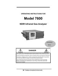
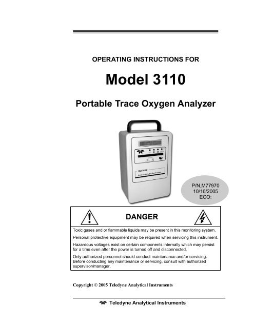
Introduction <strong>Model</strong> <strong>3110</strong>Introduction1.1 IntroductionThe <strong>Teledyne</strong> <strong>Analytical</strong> <strong>Instruments</strong> (TAI) <strong>Model</strong> <strong>3110</strong> PortableTrace Oxygen Analyzer is a portable, intrinsically safe oxygen analyzercapable of analyzing oxygen levels from 2 parts per million (ppm)oxygen.The instrument operates from internal rechargeable batteries and issupplied with a universal AC charge adapter. Featuring quickdisconnect fittings for sample connections and a rugged lightweighthousing with handle, this versatile instrument can be brought to thesample site and set up for analysis quickly and easily. Because of theintrinsically safe design, once calibrated, the instrument can beemployed even in hazardous environments without compromise. The<strong>Model</strong> <strong>3110</strong> incorporates a large standard feature list designed forversatile, accurate oxygen analysis for a wide range of applications.Figure 1-1 shows the standard <strong>Model</strong> <strong>3110</strong> Portable Trace OxygenAnalyzer.The microprocessor based <strong>Model</strong> <strong>3110</strong> instrument provides usersettable analysis ranges at the trace level. The range can be set from 0-2ppm to 0-25% oxygen. In auto-ranging mode two ranges can be set andthe analyzer move between these ranges as required. The adjustmentresolution is 0.1 ppm for trace analysis.Sample oxygen is displayed on a 2-line 20 character alphanumericLCD display mounted on the front panel. Four buttons are used tointerface with the instrument and access all of the analyzer features.Sample gas is introduced and vented via a pair of quick-disconnectfittings that feature integral shutoff valves that automatically close whenthe mating male fitting is withdrawn. The fittings are an integral part ofthe measuring cell manifold.10 <strong>Teledyne</strong> <strong>Analytical</strong> <strong>Instruments</strong>
Portable Trace Oxygen AnalyzerIntroductionWARNING Though the <strong>3110</strong> can be applied to monitor percentoxygen, doing so will lead to more frequent sensorreplacement requirements.Figure 1-1: <strong>Model</strong> <strong>3110</strong> Portable Trace Oxygen Analyzer1.2 FeaturesThis instrument is designed to be a versatile analytical instrumentand to perform reliably and accurately in analyzing oxygenconcentrations in gas mixtures from the ppm level through 25% oxygen.The following features are standard on the <strong>Model</strong> <strong>3110</strong>:• Data Logger: The optional built-in data logging featureallows the user to specify the time intervalbetween data recording sets. The date,time, and oxygen concentration readingsare stored in internal RAM at the userspecified interval. The data set can be<strong>Teledyne</strong> <strong>Analytical</strong> <strong>Instruments</strong> 11
Introduction <strong>Model</strong> <strong>3110</strong>downloaded using the instrument’soptional RS-232 interface.• Display: A 2-line 20 character alphanumeric LCDon the front panel displays data andoperational information through variousscreens. The contrast is adjustable forvarious lighting conditions.• Four-Button User Interface: Operation is performed using thefour front panel mounted buttons. Thesebuttons are used to enter data, select itemsand move through operational screens thatappear on the display.• Universal AC Charge Adapter: The rechargeable batteries canbe recharged without removing them fromthe instrument. The charger operates overthe range of 100-240 VAC.• LEDs: Two front panel mounted LEDs are usedto indicate low battery condition and whenthe battery is recharging.• Contrast Control: This feature allows the user to easilyadjust the contrast of the display foroptimum viewing under different lightingconditions. The adjustment is made usinga front panel control dial.• Auto-ranging: The user is able to specify two analyticalranges for analysis in the auto mode. The<strong>Model</strong> <strong>3110</strong> will automatically switchbetween these ranges depending on theoxygen level.• Percent of Range Voltage Output: An optional 0-1 VDCoutput is available that represents thepercentage of the current analysis range.• Real-time Clock: This feature allows the <strong>Model</strong> <strong>3110</strong> to dateand time stamp the data set recorded onthe data logger. It uses a 24 hour clock.12 <strong>Teledyne</strong> <strong>Analytical</strong> <strong>Instruments</strong>
Portable Trace Oxygen AnalyzerIntroduction• Quick Disconnect Fittings: Dual self-sealing quick disconnectfittings are installed for making easysample connections.1.3 Method of AnalysisThe sample oxygen is measured by a unique electrochemicaltransducer which functions as a fuel cell; in this instance, the fuel isoxygen. Oxygen diffusing into the cell reacts chemically to produce anelectrical current that is proportional to the oxygen concentration in thegas phase immediately adjacent to the transducer’s sensing surface. Thelinear, but minute signal produced by the transducer from oxygen isamplified by a two-stage amplifier. The O2 sensor output signal isdigitized and fed to the microprocessor. Additional signal conditioningand temperature compensation are handled electronically andappropriate signals are directed to the display and output ports.1.4 Micro-Fuel CellThe micro-fuel cell (U.S. Pat. Nos. 3,767,552 and 3,668,101) is asealed electrochemical transducer with no electrolyte to change orelectrodes to clean. When the cell reaches the end of its useful life, it isremoved, properly disposed of, and replaced with a new cell. The life ofthe cell is warranted by TAI (see below).The cell is specific for oxygen and is not sensitive to flow rate orreducing agents such as hydrocarbons, carbon monoxide, sulfur dioxide,etc. In the absence of oxygen, no current is produced; thus, no zeroing isrequired.1.4.1 Cell WarrantyThe Class B2-C, A2C, B2C-XL and Insta Trace micro-fuel cellscan be used in the <strong>Model</strong> <strong>3110</strong> and are warranted for six (6) monthsfrom the date of shipment.With regard to spare cells, service time starts when the cell isremoved from its shipping package. You should stock only one sparecell per instrument at a time.If a cell was working satisfactorily but ceases to function before thewarranty period expires, the sensor will be replaced at no cost.<strong>Teledyne</strong> <strong>Analytical</strong> <strong>Instruments</strong> 13
Introduction <strong>Model</strong> <strong>3110</strong>If you have a warranty claim, return the cell in question to thefactory for evaluation. If it is determined that failure is due to faultyworkmanship or material, the cell will be replaced at no cost to you.WARNING:EVIDENCE OF DAMAGE DUE TO TAMPERING ORMISHANDLING WILL RENDER THE CELLWARRANTY NULL AND VOID.The <strong>Model</strong> <strong>3110</strong> is designed to meet Factory Mutual standards forintrinsically safe for Class I, Division I, Groups A, B, C and Dhazardous locations. (Approval pending at time of manual printing.)This safety feature does not apply when the instrument is beingcharged with the 100- 240 VAC external charge adapter. The instrumentshould be removed from hazardous areas when the batteries are beingcharged.Note: Do not use the analyzer when the battery charge is low.1.5 Accuracy and ResponseThe <strong>Model</strong> <strong>3110</strong> provides monitoring accuracies of ±2% of fullscale or ±1 ppm, whichever is greater, at constant temperature.With a sample flow rate of 1 SCFH, a 90% response can be realizedin 60 seconds. The response time on the <strong>3110</strong> is limited by the filtersetting.1.6 Signal OutputThe standard 0-1 VDC output has a 100 ohm impedance and issuitable for driving external devices that have an input impedance of10,000 Ω or more. The signal output is available from a port on the rearpanel.1.7 Compact PackagingThe instrument is housed in 6 1/8" × 9 ½" × 5 5/8" (156 × 241 ×143 mm) aluminum case that is equipped with a carrying handle andfoot pads. Unlike analog instruments where uneven positioning may14 <strong>Teledyne</strong> <strong>Analytical</strong> <strong>Instruments</strong>
Portable Trace Oxygen AnalyzerIntroductionaffect meter accuracy, the <strong>Model</strong> <strong>3110</strong> can be used in any positionwithout interference.<strong>Teledyne</strong> <strong>Analytical</strong> <strong>Instruments</strong> 15
Introduction <strong>Model</strong> <strong>3110</strong>Intentionally left blank.16 <strong>Teledyne</strong> <strong>Analytical</strong> <strong>Instruments</strong>
Portable Trace Oxygen AnalyzerInstallationInstallationThe <strong>Model</strong> <strong>3110</strong> Trace Oxygen Analyzer is designed to be portableand easy to setup and configure. To setup the analyzer:• Read the Manual• Charge the battery• Install the sample and vent gas lines• Install the trace sensor and purge the analyzer• Calibrate the analyzer• Set the sample gas flow rate2.1 Charging the BatteriesThe unit is powered by 2 Intrinsically Safe rated sub-C Ni-Cdbatteries and is shipped with batteries fully charged. The batteries,however, will require periodic recharging. For recharging, access to anAC power source of 100 to 240 volt, 50/60 Hz will be required and theinstrument should not be recharged in a hazardous area. Connect theuniversal AC charger adapter supplied with the instrument to the ACpower outlet. Plug the other end of the charger into the port on the rearpanel as shown in Figure 2-1. The green charge indicator LED should beilluminated to indicate that the unit is charging.To fully recharge a set of batteries will take approximately 16hours. The instrument should not be left on the charger for longer than20 hours nor should the charger be left attached to the instrument whenthe unit is not charging. The <strong>Model</strong> <strong>3110</strong> cannot be operated while thebattery charger is attached.CAUTION:DO NOT CHARGE THE BATTERY IN A HAZARDOUSAREA. THE INTRINSICALLY SAFE CLASSIFICATIONOF THIS INSTRUMENT DOES NOT APPLY WHENTHE CHARGER IS ATTACHED TO THEINSTRUMENT. REMOVE THE INSTRUMENT TO ANON-HAZARDOUS AREA BEFORE CONNECTINGTHE BATTERY CHARGER TO THE INSTRUMENT.<strong>Teledyne</strong> <strong>Analytical</strong> <strong>Instruments</strong> 17
Installation <strong>Model</strong> <strong>3110</strong>The unit can operate continuously for approximately 4 days on a setof fully charged batteries. If more frequent charging is required, thebatteries are approaching the end of their useful life and should bereplaced. See Battery Replacement in Section 4.3 of this manual.A low battery condition is indicated by a blinking red Low BatteryLED on the front panel. This will also cause the display to flicker alongwith the blinking LED due to the power drain and low battery condition.At this point the unit should be removed from service and the batteriesrecharged.Figure 2-1: <strong>Model</strong> <strong>3110</strong> Rear Panel2.2 Gas ConnectionsThe customer must provide a means of controlling the pressure andflow rate of the sample and zero gas. For positive pressure applications,TAI suggests a simple throttle valve installed in the sample line betweenthe sample point and the analyzer. The flow rate should be limited tobetween 0.2 and 2.5 SCFH. The sample in port is used for both sample18 <strong>Teledyne</strong> <strong>Analytical</strong> <strong>Instruments</strong>
Portable Trace Oxygen AnalyzerInstallationand calibration gas. For atmospheric pressure sampling, connect a pumpand flow control valve downstream from the analyzer and draw (ratherthan push) the sample through the instrument.IMPORTANT: IF A PRESSURE REGULATOR IS USED, IT MUSTHAVE A METALLIC DIAPHRAGM. REGULATORSWITH ORGANIC OR PLASTIC DIAPHRAGMS AREPERMEABLE TO OXYGEN AND, IF USED IN THESAMPLING SYSTEM, WILL LEAD TO HIGH OXYGENREADINGS.The instrument is shipped with a gas sampling and calibration kit.This includes a 12” piece of clear tubing with a quick disconnect line foruse as a sample return or vent line plus 2 quick disconnect fittings to beinstalled on the sample and calibration lines. These fittings employ ¼”tube fittings which can be removed to reveal a 1/8” NPT internal thread.It is important in trace analysis applications to use metal for allwetted components of the sample system. This includes gas lines, filters,pump housing, diaphragms and any components in contact with thesample gas. Plastic tubing and parts will result in slow and inaccuratemeasurements at the ppm level.There are two quick disconnect fittings installed on the rear panelfor mating the instrument with the sample or calibration gas and the ventline. As shown in Figure 2-1, each fitting has a button which whendepressed allows the rapid detachment of the gas line from theinstrument. It is not necessary to press the button when inserting theline, just push the male fitting into the mating connector. When a line isremoved, an internal seal prevents gas escape from the female sectionsof the fitting.To avoid pressurizing the sensor, the vent line should beinstalled first and removed last.In setting up the sample lines, any valves used to set the sampleflow or filters must be located on the sample in line. Do not place anyvalves or restrictions on the vent line except as noted above foratmospheric pressure sampling when using a downstream pump. Doingso would increase the sensor operating pressure and result in inaccurateanalysis.<strong>Teledyne</strong> <strong>Analytical</strong> <strong>Instruments</strong> 19
Installation <strong>Model</strong> <strong>3110</strong>For trace analysis applications, a flowmeter should be installed inthe vent line but it should not incorporate any control valves orrestrictive devices.2.3 Sensor InstallationThe <strong>Model</strong> <strong>3110</strong>'s trace sensor requires that the instrument lines beimmediately purged with zero gas after installing the cell.2.3.1 Installing a Trace SensorPrior to installing the trace sensor, make sure the analyzer is readyto purge with zero gas. Connect the vent line to the analyzer thenconnect the zero gas line to the sample in port. Set the zero gas flow ratebetween 0.2 and 2.5 SCFH.Prior to using any bottled gas for calibration or purge, it is goodpractice to bleed the regulator and sample line to remove any traces oftrapped air. See Section 2.4.3 Bleeding the Regulator and Purging theGas Line.Once the vent and zero gas lines are attached and the lines bleed,proceed to install the trace sensor as follows:1. Remove the cell holder cap from the bottom of theinstrument.2. Remove the outer packaging from the sensor.3. Grab the shorting plug on the top of the sensor and pull itfree prior to removing the sensor from its packaging.4. Remove the packaging and rapidly place the sensor on thetop of the cell holder cap with the concentric gold ringsfacing up.5. Screw the cell holder cap and sensor into the bottom of theanalyzer.Note: Minimize the time the sensor is exposed to air.6. Start the purge flow through the analyzer and purgeovernight before calibrating the unit.20 <strong>Teledyne</strong> <strong>Analytical</strong> <strong>Instruments</strong>
Portable Trace Oxygen AnalyzerInstallation2.4 CalibrationCalibration involves using a span gas to set the span of theinstrument. The proper span gas concentration depends on the range thatthe instrument will be used on. The correct concentration should be 80-90% of the range used. For instance, if the analyzer is to be used on arange of 0-150 ppm oxygen, then a span gas should be prepared with120-135 ppm oxygen in nitrogen.2.4.1 Calibration Procedure for Trace AnalysisTo calibrate the <strong>Model</strong> <strong>3110</strong>, the instrument must be fitted with atrace sensor. The instrument must also be purged overnight using a zerogas (a pure gas with no oxygen, typically O 2 free N 2 ) before calibrating.For A-2C type cells, match the CO2 content in the span gas to that of thesample gas.To calibrate the analyzer for trace analysis:1. Purge the analyzer overnight.2. Purge the calibration gas sample line, regulator, and controlvalve. See Section 2.4.3.3. Set the calibration gas flow rate to 1 SCFH.4. Attach the vent line followed by the span gas line using thequick disconnect fittings.5. Navigate to the SPAN VALUE screen (see Section 3.2.13)and set the span value to the known oxygen concentration inppm of the span gas.6. Observe the oxygen reading on the screen to determine whenthe reading has stabilized.7. Navigate to the SPAN screen and select SPAN: START.8. When the screen changes and displays SPAN: FINISH, selectSPAN: FINISH to set the span.9. Allow the span gas to flow for several minutes to verify theproper span setting.10. Calibration is complete. Remove the span gas line firstfollowed by the vent line.<strong>Teledyne</strong> <strong>Analytical</strong> <strong>Instruments</strong> 21
Installation <strong>Model</strong> <strong>3110</strong>2.4.2 Bleeding the Regulator and Purging the Gas LineWhen using bottled gas (gas cylinder) as a calibration gas for traceanalysis applications, the regulator and sample lines must be bled toremove traces of trapped air. Otherwise air that is trapped in the linesespecially between the regulator and cylinder will result in a lengtheningof the calibration time.To bleed the regulator and sample line:1. Attach the regulator to the gas cylinder. Then attach a sampleline with a flow control/shut off valve preferably at the farend of the sample line.2. Open the shut off valve slightly, and then open the valve onthe gas cylinder.3. Adjust the regulator to the desired pressure (usually 5 psi)then close the cylinder valve.4. Open the cylinder valve to pressurize the regulator fully thenclose the cylinder valve again.5. Open the sample flow control valve and allow the gas tobleed down and vent to a safe area. Observe the secondarygauge (low pressure side) on the regulator. As the lowpressure gauge starts to fall, close the sample flow controlvalve.6. Repeat steps 4 and 5 seven (7) times.The sample delivery system is now purged and ready for calibrationor analysis. Keep the cylinder valve open to maintain systempressurization.Note: Make sure there are no leaks in the sample line andregulator connections. Check also the cylinder connectionfor leaks.2.5 Set the Sample Flow rateOnce the system has been calibrated, the instrument can be broughtto the analysis site and the sample gas line can be connected to the unit.Using the quick disconnect fittings supplied; connect the vent linefollowed by the sample line to the rear panel. See Figure 2-1.Once the sample gas is flowing, set the flow rate to 0.2-2.5 SCFH.22 <strong>Teledyne</strong> <strong>Analytical</strong> <strong>Instruments</strong>
Portable Trace Oxygen AnalyzerInstallation2.6 External SignalThe standard 0-1 VDC output signal represents the percentage ofthe current range. For instance, if the range was set for 0 to 10 ppm, then0.1 V would represent 1 ppm, 0.2V would be 2 ppm; 0.3V would be 3ppm etc.This output signal, when installed, is accessible from the rear panel.The output signal has an input impedance of 100Ω.<strong>Teledyne</strong> <strong>Analytical</strong> <strong>Instruments</strong> 23
Operation <strong>Model</strong> <strong>3110</strong>OperationThe micro-fuel cell is not installed in the analyzer prior toshipment. It is be a separate item that is to be installed according theprocedure in section 2.3 of this manual. Once the cell is installed andpurged down with zero gas, the integral shut-off valves in the quickdisconnect sample fittings, if not disturbed, will maintain this inertatmosphere within the manifold indefinitely.Turning the instrument on by pressing the ENTER key will powerthe display and show the power on screen briefly. The display will thenchange to indicate the residual oxygen concentration within the internalsample passageways if no sample line is attached.Note: To extend cell life and minimize the time required to makethe next analysis, the instrument should always be purgedwith an oxygen free inert gas prior to being taken out ofservice for standby or storage.3.1 Front Panel InterfaceThe <strong>Model</strong> <strong>3110</strong> is controlled from the keys on the front panel andis shown in Figure 3-1. These keys are also used to setup the instrumentfor your application. The keys are:• ENTER/ON• ESC• UP/DOWN3.1.1 ENTER KeyThe ENTER key is context sensitive. It is used as follows:• Powering ON or OFF—Pressing the ENTER key turns thepower ON. The ENTER key is also used the power OFFfrom within the POWER OFF screen.• Enter SETUP—In certain menus, pressing the ENTER keyselects a setup screen for that particular function. Navigation24 <strong>Teledyne</strong> <strong>Analytical</strong> <strong>Instruments</strong>
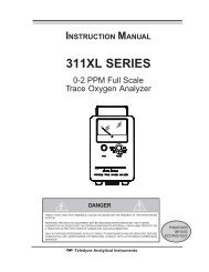
Portable Trace Oxygen AnalyzerOperationarrows on the left and right of the bottom line identify thesescreens as setup screens by changing from UP/DOWN toLEFT/RIGHT. The setup screens also blink.• Select a value—When multiple options or values exist for afunction, pressing ENTER selects the currently displayedoption.• Save changes—If a value or option has been modified,pressing ENTER saves the change and brings you back to theprevious screen.3.1.2 ESCAPE KeyFigure 3-1: Front Panel KeysThe ESCape key is used to exit a setup menu without saving anychanges made to that screen. The values will revert to the last valuesaved for that entry.3.1.3 UP/DOWN KeysThe UP/DOWN keys are used to:• Navigate from one screen to another• Toggle between multiple options within a menu<strong>Teledyne</strong> <strong>Analytical</strong> <strong>Instruments</strong> 25
Operation <strong>Model</strong> <strong>3110</strong>• Increment or decrement a value3.2 Operation and Setup Screens and MenusThe <strong>Model</strong> <strong>3110</strong> operation and setup functions are arranged in a setof 15 menus. All but the POWER ON screen are accessible via theUP/DOWN keys. Figure 3-2 shows the available menus and thesequence of screens when scrolling.Figure 3-2: Available Menus and Their Sequence26 <strong>Teledyne</strong> <strong>Analytical</strong> <strong>Instruments</strong>
Portable Trace Oxygen AnalyzerOperation3.2.1 POWER ON ScreenThe POWER ON screen automatically appears on the display whenthe unit is first powered up. The display appears briefly and shows themodel number and software version. After a few seconds the displayreverts to the HOME screen.3.2.2 HOME ScreenThe HOME screen displays the oxygen concentration at the level ofthe current range (ppm or %). The concentration is shown in the upperline the current range is indicated on the second line.Note: In almost all of the available screens, the first line displaysthe oxygen concentration.3.2.3 DATE ScreenUse the UP/DOWN keys to navigate to the DATE screen. Thesecond line of the DATE screen displays the current date and is used bythe data logger for date stamping data records. The currently set date isdisplayed on the second line of the display.To change the currently set date:1. Press ENTER to enter the date setup function. Note thenavigation arrows that appear on the left and right sides ofthe display change from UP/DOWN to pointingLEFT/RIGHT.<strong>Teledyne</strong> <strong>Analytical</strong> <strong>Instruments</strong> 27
Operation <strong>Model</strong> <strong>3110</strong>2. Use the UP/DOWN keys to alter the month. Then pressENTER. The cursor will move over to the next editable field.3. Use the UP/DOWN keys to alter the day. Then pressENTER. The cursor will move over to the next editable field.4. Use the UP/DOWN keys to alter the year. Then pressENTER.5. Press ENTER again to save the current date andautomatically return to the DATE screen.At any time you can press the ESC key to abort the entry and returnto the DATE screen.3.2.4 TIME ScreenUse the UP/DOWN keys to navigate to the TIME screen. Thesecond line of the this screen displays the current time in 24 hourmilitary format. This information is used by the data logger for timestamping data records. The currently set time is displayed on the secondline of the display.To change the currently set time:1. Press ENTER to enter the time setup function. Note thenavigation arrows that appear on the left and right sides ofthe display change from UP/DOWN to pointingLEFT/RIGHT.2. Use the UP/DOWN keys to alter the hour field. Then pressENTER. The cursor will move over to the next editable field.3. Use the UP/DOWN keys to alter the minute field. Then pressENTER. The cursor will move over to the next editable field.4. Use the UP/DOWN keys to alter the seconds field. Thenpress ENTER.5. Press ENTER again to save the current time andautomatically return to the TIME screen.28 <strong>Teledyne</strong> <strong>Analytical</strong> <strong>Instruments</strong>
Portable Trace Oxygen AnalyzerOperationAt any time you can press the ESC key to abort the entry and returnto the DATE screen.3.2.5 STANDARD ALARM ScreenNote: Alarm relays are not included on the standard version of the<strong>3110</strong>.During an alarm a blinking “AL” will appear in the upper rightcorner of the display. Use the UP/DOWN keys to navigate to theSTANDARD ALARM screen. This screen displays the alarm setpoint onthe lower line. You can change the setpoint and on this screen.To change the alarm setpoint or toggle between ppm and %:1. Press ENTER to enter the alarm setup function. Note thenavigation arrows that appear on the left and right sides ofthe display change from UP/DOWN to LEFT/RIGHT2. Use the UP/DOWN keys to alter the value in the setpointfield. Then press ENTER to accept this new value. Thecursor will move over to the next editable field.3. Use the UP/DOWN keys to toggle between PPM or % thenpress ENTER to accept the change.4. Press ENTER again to save the setpoint changes and returnto the STANDARD ALARM screen.3.2.6 ALARM EnableThe next four screens determine the characteristics of the alarm:whether it is on or off, failsafe or non-failsafe, HI or LOW activating, orlatching or non-latching in its operation.From the ALARM ENABLE screen you can set whether the alarm ison or off.<strong>Teledyne</strong> <strong>Analytical</strong> <strong>Instruments</strong> 29
Operation <strong>Model</strong> <strong>3110</strong>To enable or disable the alarm:1. Use the UP/DOWN keys to navigate to the ALARM ENABLEscreen. Then press ENTER to enter the alarm setup screen.2. Use the UP/DOWN keys to toggle between ENABLED orDISABLED. Then press ENTER to accept the displayedstatus.3. Press ENTER again to save the alarm status and return to theALARM ENABLE screen.3.2.7 FS ALARM ScreenThis screen indicates how the alarm relays activate—failsafe ornon-failsafe. In failsafe mode the relays are energized when analyzer isNOT in alarm mode. In non-failsafe mode the alarm relay energizeswhen the analyzer goes into alarm mode. You can change the alarmrelay behavior by entering the FS ALARM setup screen.To toggle between failsafe and non-failsafe operation:1. Use the UP/DOWN keys to navigate to the FS ALARMscreen. Then press ENTER to enter the setup screen.2. Use the UP/DOWN keys to toggle between FS or NON-FSoptions. Then press ENTER to accept the displayed status.3. Press ENTER again to save the alarm status and return to theFS ALARM screen.3.2.8 HI-LOW ALARM ScreenThe HI-LO screen indicates how the <strong>Model</strong> <strong>3110</strong> alarm functions.The alarm on the <strong>Model</strong> <strong>3110</strong> can be set up as either a HI alarm or LO30 <strong>Teledyne</strong> <strong>Analytical</strong> <strong>Instruments</strong>
Portable Trace Oxygen AnalyzerOperationalarm. A HI alarm activates when the oxygen concentration rises abovethe setpoint. The LO alarm activates when the oxygen concentrationfalls below the setpoint.To set the alarm as either a HI or LO alarm:1. Use the UP/DOWN keys to navigate to the HI-LO ALARMscreen. Then press ENTER to enter the setup screen.2. Use the UP/DOWN keys to toggle between HI and LOoption. Then press ENTER to accept the displayed status.3. Press ENTER again to save the alarm status and return to theHI-LO ALARM screen.3.2.9 LTCH ALARM ScreenThe alarm on the <strong>Model</strong> <strong>3110</strong> can be set up as latching or nonlatching.A latching alarm, once triggered, will remain in alarm statusuntil recognized and reset. Even if the concentration changes back to anon-alarm concentration, a latched alarm will remain in alarm status. Anon-latching alarm will cease to alarm when the concentration falls orrises to a non-alarm value.To set the alarm to either latching or non-latching:1. Use the UP/DOWN keys to navigate to the LTCH ALARMscreen. Then press ENTER to enter the setup screen.2. Use the UP/DOWN keys to toggle between LTCH and NON-LTCH options. Then press ENTER to accept the displayedstatus.3. Press ENTER again to save the alarm status and return to theLTCH ALARM screen.<strong>Teledyne</strong> <strong>Analytical</strong> <strong>Instruments</strong> 31
Operation <strong>Model</strong> <strong>3110</strong>To reset a latched alarm that has triggered use the ALARMENABLE screen and temporarily DISABLE the alarm. See Section3.2.6. This will restore the alarm to it previous non-alarm condition.Note: A latched alarm can only be reset when the concentrationfalls or rises to a non-alarm value. (It can be disabled)3.2.10 RANGE 1 ScreenThe <strong>Model</strong> <strong>3110</strong> is capable of using two user defined ranges in theauto-ranging mode however, if the instrument is used in manual mode(see Section 3.2.12), only RANGE 1 is recognized.The RANGE 1 screen displays the current range setting for range 1on the bottom line of the display.To define or change range 1:1. Use the UP/DOWN keys to navigate to the RANGE 1 screen.Then press ENTER to enter the setup screen.2. Use the UP /DOWN keys to change the value.3. The UP/DOWN keys will cycle through the ppm values.4. Press ENTER to accept the displayed unit and return to theRANGE 1 screen.Note: The range setting resolution is 0.1 PPM for trace analysis.3.2.11 RANGE 2 ScreenThe RANGE 2 screen displays the current range setting for range 2on the bottom line of the display. This range is used only when theinstrument is set for auto-ranging. See Section 3.2.12. In manual modethis range is ignored.32 <strong>Teledyne</strong> <strong>Analytical</strong> <strong>Instruments</strong>
Portable Trace Oxygen AnalyzerOperationTo define or change range 1:1. Use the UP/DOWN keys to navigate to the RANGE 2 screen.Then press ENTER to enter the setup screen.2. Use the UP /DOWN keys to change the initial value. PressENTER to accept the displayed value and to return to theRANGE 2 screen.Note: The range setting resolution is 0.1 PPM for trace analysis.Note: Make sure that the instrument is set for auto-ranging if youexpect to use this analysis range.3.2.12 Range ScreenThe RANGE screen indicates whether the instrument is currently inmanual or auto-ranging mode. When in manual mode, only range 1 isavailable. In auto-ranging mode, range 1 and range 2 are available andthe instrument will automatically switch between ranges as dictated bythe analysis.To switch between manual and auto-ranging modes:1. Use the UP/DOWN keys to navigate to the RANGE screen.Then press ENTER to enter the setup screen.2. Use the UP/DOWN keys to toggle between MAN and AUTOfor the range mode. Press ENTER to accept the displayedmode.3. Press ENTER again to return to the RANGE screen.<strong>Teledyne</strong> <strong>Analytical</strong> <strong>Instruments</strong> 33
Operation <strong>Model</strong> <strong>3110</strong>3.2.13 SPAN VALUE ScreenThe SPAN VALUE screen displays the oxygen concentration of thespan gas used for calibration. This is not a measured value; it is theknown span gas concentration that is input to the analyzer by theoperator.To change the span gas concentration:1. Use the UP/DOWN keys to navigate to the SPAN VALUEscreen. Then press ENTER to enter the setup screen.2. Use the UP /DOWN keys to change the span value. PressENTER to accept the displayed value and to return to theSPAN VALUE screen.3.2.14 SPAN ScreenThis screen is used to perform a span calibration on the <strong>Model</strong><strong>3110</strong>. The appropriate span value must have already been input to theinstrument. See Section 3.2.13 for entering a span value into theanalyzer.CAUTION:THE CORRECT SPAN VALUE MUST BE ENTEREDINTO THE INSTRUMENT THAT CORRESPONDS TOTHE ACTUAL SPAN GAS USED. FAILURE TO ENTERTHE PROPER VALUE WILL RESULT IN ERRONEOUSREADINGS.Note: The filter should be set to a low value to avoid errorsduring span setting. Allow the oxygen reading to become stableprior to setting the span.To perform a span calibration:34 <strong>Teledyne</strong> <strong>Analytical</strong> <strong>Instruments</strong>
Portable Trace Oxygen AnalyzerOperation1. Use the UP/DOWN keys to navigate to the SPAN screen.Then press ENTER to start the span calibration.Once the span calibration has begun the screen changes to reveal aspan finish selection.2. When the FINISH selection appears, press ENTER to end thespan calibration. The analyzer will accept the calibration andreturn to the HOME screen.Note: After successfully performing a span calibration, you arereturned directly to the HOME screen rather than back tothe previous menu.3.2.15 Filter ScreenThe <strong>3110</strong> includes user adjustable filter. The filter has settings 1-10. Setting 1 is the least amount of filtering and 10 is the highest level ofdamping. The filter is used to reduce the noise level of the O 2 readings.More filtering is required for lower trace ranges such as 10 ppm. Addingfiltering will slow down analyzers response to changing O 2 levels. Thelowest effective level of filtering should always selected. The filter levelshould be lowered to 1or 2 when setting the span to avoid delays. For a0-10 ppm range a filler setting or 6 or 7 should typically provide goodresults.<strong>Teledyne</strong> <strong>Analytical</strong> <strong>Instruments</strong> 35
Operation <strong>Model</strong> <strong>3110</strong>To use this feature:1. Use the UP/DOWN keys to navigate to the FILTER screen.Then press ENTER to enter the setup screen.2. Use the ENT/ON key to change the filter to the active mode.The arrows will point left and right and the filter setting willblink.3. Use the UP/DOWN keys to select the desired setting.4. Select the ENT/ON key to save the setting and to return tothe non-active mode on the filter screen.3.2.16 LOG INTV ScreenThis screen indicates the time interval between data samples taken bythe data logger. The interval can be set between 1 second (00m 01sec) to 60minutes (60m 00sec) in increments of 1 second.To change the interval between data samples:1. Use the UP/DOWN keys to navigate to the LOG INTVscreen. Then press ENTER to enter the setup screen.2. Use the UP /DOWN keys to change the interval value. Thevalue of the seconds will increase or decrease followed bythe minutes. Press ENTER to accept the displayed value andreturn to the LOG INTV screen.3.2.17 LOG RESET & START ScreenOnce a log interval has been input, the LOG RESET & STARTscreen is used to start the data logger.The data logger has a 3200 record capacity and each record uses 10bits of data. The data set is retained until it is reset by using the START36 <strong>Teledyne</strong> <strong>Analytical</strong> <strong>Instruments</strong>
Portable Trace Oxygen AnalyzerOperationRESET menu again. The data set can be downloaded using the LOGTRANSMIT screen (see Section 3.2.17).To start the data logger:1. Use the UP/DOWN keys to navigate to the LOG RESET &START screen and press ENTER.2. When the screen begins to blink press ENTER again to startthe data logger. Once the data logger has started, the screenchanges RESET&START to STOP. During logging ablinking “L” appears in the upper left corner of the screen.To stop the data logger:1. Press ENTER to stop the data logger and return to the LOGRESET & START screen.3.2.18 LOG TRANSMIT ScreenData can be downloaded to a computer using the optional RS-232port and cable attached to a PC. The RS-232 port accepts a standard datacable with a DB-9 connector. The computer must be able to accept datafrom a RS-232 source with the following characteristics:9600 baud8 bit datano parity<strong>Teledyne</strong> <strong>Analytical</strong> <strong>Instruments</strong> 37
Operation <strong>Model</strong> <strong>3110</strong>1 stop bitno flow controlRefer to your computer manual for details on how to setup theoptional RS-232 communications port on your computer.To download a data log:1. Use the UP/DOWN keys to navigate to the LOG TRANSMITscreen. Then press ENTER to enter the setup screen.2. Press ENTER again to transmit the current data log.Note: The data set will be transmitted each time you press theENTER key. Use the ESC key to exit the LOG TRANSMITmenu.3. Press ESC to exit out of the LOG TRANSMIT screen and goto the home screen.Note: The Date Log does not need to be stopped in order totransmit the date.3.2.19 POWER DOWN ScreenThis screen is used to power off the instrument.To turn the analyzer off:38 <strong>Teledyne</strong> <strong>Analytical</strong> <strong>Instruments</strong>
Portable Trace Oxygen AnalyzerOperation1. Use the UP/DOWN keys to navigate to the POWER DOWNscreen. Then press ENTER.2. Press ENTER again to turn the instrument OFF.In a few seconds the analyzer will turn off.<strong>Teledyne</strong> <strong>Analytical</strong> <strong>Instruments</strong> 39
Maintenance <strong>Model</strong> <strong>3110</strong>Maintenance & Troubleshooting4.1 Routine MaintenanceOther than replacing the sensor and cell holder O-ring, there are nouser-serviceable components within the instrument housing. Routinemaintenance consists of wiping down the instrument case, cleaning thescreen and checking for leaks.CAUTION:USING ABRASIVE CLEANSERS OR SOLVENTS WILLDAMAGE THE SCREEN. USE ONLY A MILDDETERGENT AND SOFT CLOTH WHEN REMOVINGDIRT OR GREASE MARKS FROM THE SCREEN.When cleaning the instrument case, do not flood with water or useharsh, abrasive or solvent cleansers. These cleansers will attack the LCDlens material as well as eventually wear off the silk-screened legends.4.2 Opening the Instrument CaseCAUTION:DEPENDING ON THE APPLICATION, IT MAY BENECESSARY TO PURGE THE INSTRUMENT THENREMOVE THE INSTRUMENT TO A NON-HAZARDOUS AREA BEFORE OPENING THEINSTRUMENT CASE.To open the enclosure:1. Loosen (counter-clockwise) the three (3) ¼-turn screwdrivertypefasteners on the back of the outer enclosure.2. Pull off the back section of the cover4.3 Replacing the BatteryAfter many charge/recharge cycles of the battery, eventually theNi-Cd batteries will have to be replaced. Usually, when the instrumentrequires more frequent charge cycles than before it is time to change the40 <strong>Teledyne</strong> <strong>Analytical</strong> <strong>Instruments</strong>
Portable Trace Oxygen AnalyzerMaintenancebatteries. Refer to the Spare Parts Listing in the Appendix for the correctreplacement battery.Note: The batteries are not user serviceable. They can only bereplaced by a qualified technician.4.4 Battery Power Supply ServiceThe <strong>Model</strong> <strong>3110</strong> is designed to be intrinsically safe, and is designedfor use only when not connected to the AC power line. TAI suggeststhat an overnight recharge be performed every few days for continuoususe.The low battery LED will begin to blink and the display will flickerwhen the batteries are getting low. At this point, the batteries should berecharged. To recharge the batteries, turn the instrument OFF (seeSection 3.2.19. Remove the instrument to a safe non-hazardous location.Note: Depending on the application, purging may be requiredbefore disconnecting the analyzer and moving it to a safelocation.Plug the AC charger into a suitable 100-240 VAC 60 Hz powersource. Plug the other end of the charger cable into the port on the rearof the instrument. Figure 4-1 shows the AC charger port on the rearpanel.Note: During charging, the green battery charging indicator LEDwill illuminate.When recharging is completed, unplug the unit from the AC outletand disconnect the cable from the AC charger port.Note: The analyzer cannot be turned on while the AC charger isattached.<strong>Teledyne</strong> <strong>Analytical</strong> <strong>Instruments</strong> 41
Maintenance <strong>Model</strong> <strong>3110</strong>Figure 4-1: Battery Charger Port on the <strong>Model</strong> <strong>3110</strong>4.5 Cell ReplacementThe characteristics of the micro-fuel cell are similar to those of aNiCad battery in that both provide an almost constant output through theiruseful life, and then fall off sharply towards zero at the end. If the samplebeing analyzed has a low oxygen concentration, cell failure will probablybe indicated by the inability to properly calibrate the analyzer. You will findthat very little span adjustment will be required to keep the analyzercalibrated properly during the duration of a given cell’s useful life. If largespan adjustments are required to calibrate the instrument, or calibrationcannot be achieved within the range of the control, the cell should beimmediately replaced. Refer to section 4.4 before replacing the cell.To offset the possibility of not having a replacement cell availablewhen it is needed, TAI recommends that a spare cell be purchasedshortly after the instrument is placed in service, and each time the cell isreplaced thereafter.The spare cell should be carefully stored in an area that is notsubject to large variations in ambient temperature (75 °F nominal), and42 <strong>Teledyne</strong> <strong>Analytical</strong> <strong>Instruments</strong>
Portable Trace Oxygen AnalyzerMaintenancein such a way as to obviate any possibility of incurring damage. Underno circumstances should you disturb the integrity of the cellpackage until the cell is to be actually used. If the cell package ispunctured and air permitted to enter, the cell will immediately start toreact to the presence of oxygen.CAUTION:THE MICRO-FUEL CELL CONTAINS KOH SOLUTION,WHICH IS CAUSTIC. SHOULD THE CELL RUPTURE,A LEAK MAY CAUSE INJURY. PLEASE REFER TOMATERIAL SAFETY DATA SHEET IN THE APPENDIXTO LEARN ABOUT POTENTIAL HAZARDS ANDCORRECTIVE ACTION IN CASE OF ACCIDENT.No tools are required to replace the cell in the instrument. Simplyunscrew (counterclockwise) the plug at the bottom of the analyzer andthe cell will drop out of the manifold cavity.Remove the new cell from its package, and carefully remove theshorting clip. Do not touch the silver-colored sensing surface of the cell,as it is covered with a delicate Teflon membrane that can be ruptured inhandling.Place the cell on the end of the cell holder cap so that the sensingsurface of the cell is in contact with the cap and the electrical contactplate end of the cell is facing upwards. Insert the cell and cap in themanifold cavity, and screw the cap back into place. Apply as muchpressure as you can with your fingers, but use no tools.After the cell has been installed, purge the instrument with an inertgas (or the sample), and then proceed as directed in section 3.1.1.4.6 Cell WarrantyThe Class B-2C, A-2C, B-2CXL and Insta Trace micro-fuel cellsused in the <strong>Model</strong> <strong>3110</strong> are warranted for six (6) months of service.With regard to spare cells, service time starts when the cell isremoved from its oxygen barrier packaging. The customer should stockonly one spare cell per instrument at a time. Do not attempt to stockpilespare cells.If the <strong>Model</strong> <strong>3110</strong> is used in trace analysis applications where CO 2is a major component in the sample, the A2C micro-fuel cell should beused. At low CO 2 concentrations (1,000 PPM or less) the standard B2C<strong>Teledyne</strong> <strong>Analytical</strong> <strong>Instruments</strong> 43
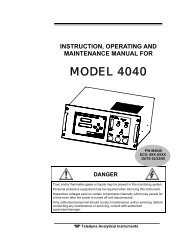
Maintenance <strong>Model</strong> <strong>3110</strong>cell performance will not be affected. On the following page is a graphshowing the effects of CO 2on cell life.WARNING:EVIDENCE OF DAMAGE DUE TO TAMPERING ORMISHANDLING WILL RENDER THE CELLWARRANTY NULL AND VOID.4.7 Temperature CompensationThe micro-fuel cell has an inherent positive temperature coefficient.Compensation is performed internally by the microprocessor and needs nofurther adjustment.Contact the factory if you suspect temperature related inaccuraciesduring monitoring and are operating within the instrument’s temperatureoperation range.44 <strong>Teledyne</strong> <strong>Analytical</strong> <strong>Instruments</strong>
Portable Trace Oxygen AnalyzerMaintenanceEffect of CO 2 on B-2 Cell Life1. This curve assumes continuous exposure.2. Intermittent exposure will extend life. Ingeneral, the CO 2effect is cumulative andthe average CO 2concentration should beused to find the predicted cell life.3. Cells can be used to make spot checkmeasurements of O 2in the presence ofhigh concentrations of CO 2(up to 50%and more). Any sample containing CO 2should be purged as soon as a constantreading is obtained.4. Abnormally slow response and recoveryis characteristic of cells used as indicatedin notes 1, 2, and 3 above.5. The reduction in cell life is primarily dueto a drop in output. Cell life will reduceto a point where the instrument can nolonger be spanned. <strong>Instruments</strong> using B-2cells in CO 2atmospheres should bespanned at intervals of 10-20% of thepredicted cell life.6. The CO 2effect on B-2 cells isindependent of the O 2level. Usage inCO 2contributes significantly to cell lifereduction and thus affects cell warranty.Figure 4-2: Effects of CO2 on B-2 Cell Life<strong>Teledyne</strong> <strong>Analytical</strong> <strong>Instruments</strong> 45
Maintenance <strong>Model</strong> <strong>3110</strong>4.8 Leak TestingWARNING:IF A LEAK IS SUSPECTED IN THE UNIT, DO NOTATTEMPT TO TIGHTEN THE QUICK DISCONNECTFITTINGS. THE FITTINGS ARE POTTED IN EPOXYAND TIGHTENING THEM WILL BREAK THE SEAL.To check for leaks, TAI recommends one of the followingprocedures:Procedure I:1. Purge the instrument to as low a value as possible. Use asensitive range for analysis for instance, 0-1% range. Takenote of the oxygen concentration.2. Place the vent line in water and disconnect the sample.3. Next, disconnect the vent line and use the same analysisrange. The reading should not increase above the level towhich you purged to.Procedure II:1. Purge the instrument with nitrogen at the sample port.2. Using a flow rate of approximately 1 SCFH, note the readingonce it has stabilized (at least 24 hours on the 0-10 PPMrange).3. Increase the flow rate from 1 SCFH to 2 SCFH.4. Note how much the reading has changed after a few minutes.5. Reduce the flow rate to 0.5 SCFH.6. Note how much the reading has changed.7. The reading should change by less than 10% of the originalvalue.46 <strong>Teledyne</strong> <strong>Analytical</strong> <strong>Instruments</strong>
Portable Trace Oxygen AnalyzerMaintenanceIntentionally left blank.<strong>Teledyne</strong> <strong>Analytical</strong> <strong>Instruments</strong> 47
Appendix <strong>Model</strong> <strong>3110</strong>AppendixA.1 SpecificationsTAI Sales Order Number:Instrument Serial Number:Micro-fuel Cell Class: B-2, A-2C, B-2CXL, Insta TransRanges of Analysis: 2 user defined ranges*Accuracy: ±2% of scale or ±1 PPM (whichever isgreater) at constant temperature;±5% of reading or ±1 PPM (whichever isgreater) over the operating temperaturerange.Operating Temp. Range: 0 °C to 40 °C (32 °F to 104 °F)Sample Temp. Range: 0-40°CSample Flow rate: 0.5 – 2.5 SCFHRecommended Span Gas: 80-90% of range most likely to be usedSignal Output: 0-1VDCDimensions: 10.9” x 6.2” x 5.2” deepWeight: 4.38 lbs. (1.99kg.)Power Requirements: 100-240 VAC 47-63H Charging Adapter* In auto range mode only48 <strong>Teledyne</strong> <strong>Analytical</strong> <strong>Instruments</strong>
Portable Trace Oxygen AnalyzerAppendixA.2 Spare Parts ListQTY P/N DESCRIPTION1 O-165 Cell Cap O-Ring (Std.)2 B27296 Battery (must be installed by a qualifiedtechnition).1 A761 Battery Charger, Universal1 CP2487 2-pin 0-1 VDC Output Plug1 A36289 Calibration Kit Std.2 F1378 Fuse 200 mA(T)1 A65476 Std. Cell Cap with O-Ring* Micro Fuel Cell Options1 C6689-B2C* Micro-Fuel Cell, Class B-2C1 C6689-A2C Micro-Fuel Cell, Class A2C1 C6689-B2C-XL Micro-Fuel Cell, Class B2C-XL1 C71792-C-1-NY-1 Insta Trace Retrofit Kit (Std.)1 C71792-C-13-NY-3 Insta Trace Retrofit Kit (XL)1 C71792-C-7-NY-2 Insta Trace Retrofit Kit (O 2 )A minimum charge of US$150.00 applies to spare parts orders.IMPORTANT: Orders for replacement parts should include the modelnumber, serial number, and range of the analyzer forwhich the parts are intended.Orders should be sent to:TELEDYNE ANALYTICAL INSTRUMENTS16830 Chestnut StreetCity of Industry, California 91748 USAPhone: (626) 934-1500FAX: (626) 934-1651or your local representativewww.teledyne-ai.com | email: ask_tai@teledyne.com<strong>Teledyne</strong> <strong>Analytical</strong> <strong>Instruments</strong> 49
Appendix <strong>Model</strong> <strong>3110</strong>IndexA2C cell, 43AC adapter. See charge adapterAC charger port, 41accuracy, 14, 48alarm, 29enable/disable, 29failsafe, 29HI/LOW, 29latching, 29, 31resetting, 32alarm setpoint, 29analysis range, 10, 48arrow, 25atmospheric pressure application, 19auto-ranging, 12, 32B2C cell, 44battery, 10, 17battery recharging, 12battery replacement, 40blinking screen, 25buttons, 12calibrateunable to, 42calibration, 20trace sensor, 21calibration kit, 19carbon monoxide, 13caution sign, ivcell holder cap, 43cell manifold, 10cell replacement, 43cell storage, 42cell warranty, 13, 43changing an alarm setpoint, 29changing ppm to %, 29changing the date, 27changing the range, 32changing the time, 28charge adapter, 10, 12charge indicator, 17charger adapter, 17cleaning the instrument, 40clock, 12CO2 component, 43combustible gas warning, ixcompany address, 49contact plate, 43continuous operation, 18, 41contrast, 12copyright, iicurrent date, 27current time, 28data logger, 27, 28, 36data logging, 11date & time setting, 11DATE screen, 27date stamping, 27DB-9 connector, 37dimensions, 48display, 10, 12downloading, 37electrochemical transducer, 13ENTER/ON key, 24ESC key, 24, 25Factory Mutual, 14failsafe. See alarmfeatures, 11filter, 35FILTER screen, 35filter setting, 14flickering display, 18, 41flow control valve, 19flow rate, 14, 18, 22, 46flow rate insensitivity, 13flowmeter, 19frequent charge cycles, 40front panel, 24front panel keys, 24gas connection, 18gas sampling, 19hazardous environment, 10, 14HI alarm, 31HI-LO screen, 30HOME screen, 2750 <strong>Teledyne</strong> <strong>Analytical</strong> <strong>Instruments</strong>
Portable Trace Oxygen AnalyzerIndexhousing, 10, 14hydrocarbons, 13impedance, 14, 23inaccurate analysis, 19incrementing a value, 26instrument position, 15intrinsically safe, 10, 14, 41leak testing, 46LED, 12LO alarm, 31LOG INTV screen, 36LOG RESET & START screen, 36LOG TRANSMIT screen, 37, 38low battery, 12, 41low battery indicator, 18, 41LTCH ALARM screen, 31maintenance, 40manual mode, 33manuals, additional, vmenu, 26micro-fuel cell, 13, 42, 44, 48microprocessor, 10, 13navigation arrows. See arrownoise, 35opening the housing, 40operating temperature, 48outputpercent of range, 12sensor, 13signal, 48voltage, 14, 22oxygen concentration, 13oxygen diffusion, 13oxygen level, 10plastic tubing, 19positive pressure application, 18power, 12, 48POWER DOWN screen, 39power off, 38power on, 24POWER ON screen, 27pressure control, 18pump, 19purge, 20, 21, 43, 46purge flow rate, 20quick disconnect button, 19quick disconnect fitting, 10, 13, 19RAM, 11range. See analysis rangeRANGE 1 screen, 32RANGE 2 screen, 32RANGE screen, 33rear panel, 18rechargeable batteries. See batteryrecharging batteries, 17recharging the batteries, 41recharging time, 17record capacity, 36regulator, 20bleeding of, 21relay, 30reset data, 36resolution, 10RS-232, 12, 37safety information, ivsample flow rate. Seesample in port, 18sample line, 22sample temperature, 48sampling interval, 36saving changes, 25screen sequence, 26selecting values, 25sensor installationtrace sensor, 20serial number, iiisetup, 17setup exit, 25setup screen, 24shorting clip, 43shutoff valve, 10signal conditioning, 13signal output. See outputsoftware version, 27span calibration, 34span gas, 20, 48span gas concentration, 20, 34SPAN screen, 34span value, 34SPAN VALUE screen, 34spare cell, 42spare cells, 13spare parts, 49STANDARD ALARM screen, 29stockpiling cells, 43sulfur dioxide, 13technician symbol, ivTeflon membrane, 43temperature coefficient, 44temperature compensation, 13, 44<strong>Teledyne</strong> <strong>Analytical</strong> <strong>Instruments</strong> 51
Appendix <strong>Model</strong> <strong>3110</strong>throttle valve, 18time format, 28TIME screen, 28time stamping, 28trace analysis application, 19trapped air, 20, 21tube fittings, 19UP/DOWN key, 24, 25user interface, 12vent line, 19, 22, 46vent line restriction, 19warning sign, ivwarranty, iiwarranty claim, 14website address, vweight, 48wetted components, 19zero, 13zero gas, 2052 <strong>Teledyne</strong> <strong>Analytical</strong> <strong>Instruments</strong>