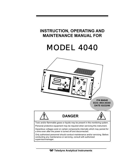
4040 - Methane / Nonmethane analyzer - Teledyne Analytical ...
4040 - Methane / Nonmethane analyzer - Teledyne Analytical ...
4040 - Methane / Nonmethane analyzer - Teledyne Analytical ...
You also want an ePaper? Increase the reach of your titles
YUMPU automatically turns print PDFs into web optimized ePapers that Google loves.
Table of ContentsSafety Messages ..........................................................................iiiAdditional Safety Information ..................................................... vProcedure for Removal of Internal Inaccessible Shock Hazards viiList of Figures.............................................................................. xiiList of Tables .............................................................................. xiiiIntroduction ................................................................................. 151.1 Main Features of the Analyzer 151.2 Principle of Operation 161.3 Analyzer Description 161.4 Applications 16Operational Theory ..................................................................... 172.1 Introduction 172.2 Sample System 182.2.2 Input Porting 182.2.2 Gas Flow Control System 202.2.3 Fuel and Blanket Air Systems 202.2.4 Flame Ionization Detection Cell 202.3 Detection Cell 202.3.1 Electrometer-Amplifier 222.3.2 Anode Power Supply 222.3.3 Flame Guard Circuit 222.3.4 Flame Ignition Circuit 22Installation ................................................................................... 253.1 Unpacking the Analyzer 253.2 Mounting the Analyzer 253.3 User Connections 263.3.1 Electrical Power Connections 26<strong>Teledyne</strong> <strong>Analytical</strong> Instrumentsix
Series <strong>4040</strong>3.3.3.1 Primary Input Power 293.3.3.2 Fuse Installation 293.3.3.3 50-Pin Equipment Interface Connector 293.3.3.4 Analog Output 293.3.3.5 Alarm Relays 303.3.3.6 Digital Remote Cal Inputs 323.3.3.7 Range ID Relays 333.3.3.8 Network I/O 333.3.3.9 Pin Out Table 333.3.4 RS-232 Port 353.3.5 Supporting Gases 353.3.5.2 Effluent 373.3.5.3 Sample Bypass Vent 373.3.5.4 Fuel and Air Connections 373.4 Placing the System in Operation 373.5 Activating the Support Gases 383.5.1 Air 383.5.2 Carrier Gas 383.5.3 Span Gas 383.5.4 Fuel 383.6 Flame Ignition 393.6.1 Verification of the Flame Guard Circuit 393.6.2 Ignition and/or Flame Guard Circuit Failure 403.6.3 Sample Pump 40Operation ..................................................................................... 434.1 Analyzer Operation 434.2 Default Parameters 444.3 Style Conventions 444.4 Navigation and Data Entry 454.4.1 Arrow Keys 454.4.2 ENTER 454.4.3 ESCAPE 464.5 Menu Structure 474.5.1 Main Menus 48x<strong>Teledyne</strong> <strong>Analytical</strong> Instruments
4.5.2 Expanded menus 494.6 Setting up an AUTO-CAL 534.7 Adjusting the GAIN 534.8 Password Protection 544.9 Logging Out 574.10 The Model Screen 584.11 System Self-Diagnostic Test 584.12 Span 594.13 The Alarms Function 604.14 The Range Function 624.15 Changing Stream 634.16 Analog output Adjustment 634.17 Standby 644.18 Advanced User Functions 654.18.1 Timing 65Appendix ...................................................................................... 67A.1 Specifications and Initial Settings: 67A.2 Recommended Spare Parts List 68A.3 Drawing List 69<strong>Teledyne</strong> <strong>Analytical</strong> Instrumentsxi
Series <strong>4040</strong>List of FiguresFigure 1-1: 19” Rack Piping Diagram-Model 4060 ..................... 22Figure 1-2: Flame Ionization Cell................................................... 24Figure 3-1: Gas Connections......................................................... 27Figure 3-2: Equipment Interface Connector Pin Arrangement....... 29Figure 4-1: Front Panel View of Regulator and Gages.................. 48xii<strong>Teledyne</strong> <strong>Analytical</strong> Instruments
List of TablesTable 3-1: Analog Output Connections ......................................... 30Table 3-4: Alarm Relay Contact Pins ............................................ 31Table 3-5: Remote Calibration Connections.................................. 32Table 3-6: Range ID Relay Connections ....................................... 33Table 3-7: Pin out of 50 pin D-Sub Connector............................... 33Table 3-8: Commands via RS-232 Input ....................................... 35Table 3-9: Required RS-232 Options ............................................ 35<strong>Teledyne</strong> <strong>Analytical</strong> Instrumentsxiii
Series <strong>4040</strong>xiv<strong>Teledyne</strong> <strong>Analytical</strong> Instruments
IntroductionIntroduction<strong>Teledyne</strong> <strong>Analytical</strong> Instruments Series <strong>4040</strong>, <strong>Methane</strong>/ <strong>Nonmethane</strong>Analyzer, is designed to measure the quantity of variety ofhydrocarbons present in the sample gas. The Analyzer is amicroprocessor controlled digital instrument based on <strong>Teledyne</strong>’s highlysuccessful Model 402R series analog Total Hydrocarbon Analyzer,coupled with a gas separation Column and a switching valve. TheAnalyzer allows for the separation and measurement of methanehydrocarbon from the rest of the hydrocarbons in the low ppm range.1.1 Main Features of the AnalyzerThe Analyzer is sophisticated yet simple to use. A dual display onthe front panel prompts and informs the operator during all phases ofoperation. The main features of the <strong>analyzer</strong> include:1. Easy-to-use front panel interface that includes a red 5-digit LEDdisplay and a vacuum fluorescent display (VFD), driven bymicroprocessor electronics.2. High resolution, accurate readings of concentration.3. Versatile analysis with three user-definable analysis ranges.4. Microprocessor based electronics: 8-bit CMOS microprocessorwith 32 kB RAM and 128 kB ROM.5. Auto ranging allows <strong>analyzer</strong> to automatically select the properpreset range for a given measurement. Manual override allowsthe user to lock onto a specific range of interest.6. Two adjustable concentration alarms and a system failure alarm.7. Extensive self-diagnostic testing at startup and on demand.8. RS-232 serial digital port for use with a computer or other digitalcommunication device.9. Analog outputs for concentration and range identification (0-1VDC standard and isolated 4-20 mA dc).10. Superior Accuracy<strong>Teledyne</strong> <strong>Analytical</strong> Instruments 15
Series <strong>4040</strong>1.2 Principle of OperationThe sample is brought to a heated compartment (50 - 80° C perapplication) and into a sample loop and a 10-port, 2 position (Position A& B) switching valve. In valve Position B the carrier gas, nitrogen,pushes the sample into a Column to separate methane from theremaining hydrocarbons. The eluted gases are analyzed for methane inthe FID detector. In valve Position A, the flow through the Column isreversed and the carrier gas pushes the sample into the FID to detectNMH. The electrical output is directly proportional to the concentrationof the ionizable hydrocarbons present in the sample stream.1.3 Analyzer DescriptionThe standard <strong>analyzer</strong> is housed in a sheet steel equipment caseflush-mounted in a 19" rack. The front interface panel is mounted on adoor which, when opened, allows convenient access to the Analyzerelectronics. The entire front panel can slide out of the chassis to providegreater access to the electronics and to the sample system. Gas pressureand flow controls are mounted on the front panel adjacent to the LEDand VFD displays and user interface.At the rear of the instrument are ports for the introduction of air,carrier, fuel, span, and sample gas. A single 50-pin user-interface cableconnector contains input/output and alarm signals available to the user.An RS-232 port is also available at the rear panel for connection to aremote computer or other digital communication device. The Analyzer isset up for either 120 VAC 60 Hz or 230 50/60 Hz operation dependingon the customer’s requirements. The appropriate power cord for yourunit has been shipped with this instrument.1.4 Applications• Monitoring the ambient air for methane/ non-methane inchemical and petrochemical plants.• Fugitive emission monitoring.• Process emission gases in the chemical industry.• Detecting trace methane/ non-methane in air.• Detecting atmospheric pollutants.16 <strong>Teledyne</strong> <strong>Analytical</strong> Instruments
Operational Theory Series <strong>4040</strong>Operational Theory2.1 IntroductionThe sample is brought to sample loop and a 10-port switching valvekept inside a heated (Temperature: 50° - 80° C per application)SAMPLE Chamber. Using a carrier gas and a microprocessor actuatedswitching valve, a fixed volume of sample collected in the Sample Loop,is pushed into the Column maintained at a constant temperature. Theeluted gas is analyzed for methane in a FID detector. Immediately, atthe end of the analysis of methane, the Valve is switched to reverse theflow through the Column, causing propane as NMH to elute and beanalyzed.Series <strong>4040</strong> uses a Flame Ionization Detector to sense hydrocarbons.The FID was selected based on the positive performance and extensiveexperience in the use of this detector in other <strong>Teledyne</strong> <strong>analyzer</strong>s namelyModel 402R and Model 4020. The FID has proven itself to be a rugged,stable, long life sensor giving years of trouble free operation in variousapplications.A packed Column was used at a constant temperature to separatemethane from the remaining non-methane hydrocarbons.The analysis has 2 modes: <strong>Methane</strong> Mode and Non-methane Mode.1) <strong>Methane</strong> Mode (POSITION B)In this mode, the eluted sample from the column is fed to the FID forthe analysis of the methane content of the hydrocarbons.2) Non-methane Mode (POSITION A)During this mode, the FID detector is monitoring Non-methanehydrocarbons, such as propane. At the end of the cycle, the methanecontent of the sample (from Position B) is added to the NMH valueto compute THC values.<strong>Teledyne</strong> <strong>Analytical</strong> Instruments 17
Operational TheoryThe Series <strong>4040</strong> Analyzer is composed of three subsystems:1. Sample System2. Detector Cell3. Electronic Signal Processing, Display and Control2.2 Sample SystemThe Analyzer contains three (3) separate isothermal chamberscontrolled by individual PID temperature controllers, viewed just behindthe Front Panel. The three chambers, ‘SAMPLE’, ‘FID’, and‘COLUMN’ are described below.The Analyzer consists of a SAMPLE Chamber containing the 10-port switching valve and 2 sample loops. The Analyzer also consists ofan ‘FID’ chamber containing the Flame, pressure regulators, pressuregauges and flow restrictors. The ‘COLUMN’ is housed in a separate‘COLUMN’ enclosure and maintained at a close temperature.2.2.2 Input PortingThe Analyzer is equipped with ports for the introduction of air, fuel,carrier gas, span, and sample gas. It is imperative that these gases aresupplied at constant pressures using two stage stainless steel diaphragmgas regulators. The recommended pressure range is 30 to 60 psig.However, the Span gas should be supplied at a pressure of 20 psig to therestrictor fitting on the Span/Sample Manifold (optional) on the back ofthe Analyzer.18 <strong>Teledyne</strong> <strong>Analytical</strong> Instruments
Operational Theory Series <strong>4040</strong>SENSOR VENTF.I.D.SENSORSAMPLELOOP #210-PORTVALVE2 POSITIONSAMPLELOOP #2COLUMNCHAMBER(70 C TYP)9898R3107107AIR INAIR P. REG. 3 ININ123SAMPLELOOP #1465123SAMPLELOOP #1465OUT IN FUEL(H 2 )FID CHAMBER(50 - 60 C TYP)FLOWCONTROLSV1N.C.P. REG. 2 FUELR2 R1CARRIER P. REG. 1REG. 1INSAMPLE CHAMBER(50 - 80 C PERAPPLICATION)(POSITION B)CH4 MODE(POSITION A)NMH MODESAMPLEFLOWF-10.1 - 2 LPMFILTERPUMPSAMPLEVENTSAMPLE INCARRIER IN(N )2SPAN/SAMPLE MANIFOLD(OPTIONAL)SSSAMPLE SPANFigure 2-1 19” Rack Piping Diagram-Model <strong>4040</strong><strong>Teledyne</strong> <strong>Analytical</strong> Instruments 19
Operational Theory2.2.2 Gas Flow Control SystemThe Piping diagram is shown in Fig. 2-1. A 10 port switching valveis used to control and direct gas flows including sampling, back flush,and carrier gas. The fixed volume sample loop ensures the same volumeof sample injection in the Column every cycle.2.2.3 Fuel and Blanket Air SystemsStable flow is achieved by maintaining a constant pressure acrossrestrictors upstream from the cell. Each system incorporates an adjustablepressure regulator, pressure gauge, and restrictor. A flame out light isincluded to indicate when the flame fails. A fuel shut-off solenoid valve,mounted on the line that supplies fuel, stops the fuel flow in case of flamefailure. This valve is located in line with the fuel port.2.2.4 Flame Ionization Detection CellThe carrier gas containing sample and fuel are combined within a teefitting located in the isothermal chamber. The mixed gas is emitted froma burner within the sensor assembly. Blanket air is introduced into thesensor (or cell) by means of a separate fitting that is located in the basesection of the assembly. The upper half of the assembly houses theanode-igniter, collector, and flame guard thermistor.2.3 Detection CellThe upper section of the stainless steel flame ionization cell housesthe cylindrical collector electrode, the high voltage (+260 VDC) anodeignitercoil, and the sensing thermistor of the flame guard circuit (seecell cross-section Figure 2-2).WARNING:DANGEROUS HIGH VOLTAGE EXISTS AT THEANODE IGNITER COIL (+260 VDC). DO NOTATTEMPT TO DISCONNECT THE IGNITER COILCABLE OR DISASSEMBLE ANY OF THE FLAMEIONIZATION CELL COMPONENTS WITHOUTTURNING OFF THE POWER AND DISCONNECTINGTHE POWER CORD.The collector is interconnected with the electrometer-amplifier PCboard by a coaxial cable. Although the cable and fittings are intended forcoaxial service, the cable is actually being used as a shielded singleconductorconnection.20 <strong>Teledyne</strong> <strong>Analytical</strong> Instruments
Operational Theory Series <strong>4040</strong>The anode-igniter, as its name implies, serves two functions. Whenrelay K2 at PCB part number B74671 is energized, the coil becomes anelectrical heating element that glows red-hot and ignites the hydrogenfuel. When relay K2 at B74671 is de-energized, the coil is connected tothe +260 volt DC terminal of the anode-flame guard power supply PCboard. In this configuration, the necessary potential difference isestablished between the coil (anode) and collector to promote ionizationof the burned hydrocarbons. The coil functions as the high voltage anodein all three-range positions of the selector switch.The thermistor acts as the sensor in the flame guard circuit. Itsambient temperature resistance is in the 100 K ohms region. When theflame is ignited, its resistance is reduced by a factor of 100. Thethermistor is coupled to a semiconductor control circuit on the anodeflameguard power supply PC board, which will be described in afollowing section.The cell electrodes of both the anode-igniter and flame guardthermistor are connected to the electronics chassis by means of a plug-incable.Figure 2-2: Flame Ionization Cell<strong>Teledyne</strong> <strong>Analytical</strong> Instruments 21
Operational TheoryThe electrode section of the cell may be removed for inspection byturning off the power, disconnecting the electrode lead plug, andremoving the screws, which retain the electrode assembly in the sensorbody.2.3.1 Electrometer-AmplifierThe collector cable is coupled directly to a coaxial fitting located onthe electrometer-amplifier PC board. The PC board is located on the sidepanel next to but outside of the isothermal chamber. See Figure 2-1 andconsists of an electrometer amplifier and an operational amplifier. Thiscircuit is a very high-gain, current-to-voltage converter circuit, havingan input impedance measuring in the billions of ohms. It is staticsensitive and highly susceptible to contamination. Special care must betaken in handling this PC board.Refer to Section 5.5.4: Electrometer-Amplifier PC Board for moreinformation concerning the electrometer-amplifier and the other printedcircuits that follow.2.3.2 Anode Power SupplyThe high voltage anode power supply components are mounted onthe anode power supply printed circuit board. High voltage regulation isachieved through the use of series-connected zener diodes. Thesimplicity of this circuit’s design can be attributed to the extremely lowcurrent demand of the anode circuit. The positive output voltage isnominally 125 volts. Output tolerance is ±10 volts from the specified125 volts.2.3.3 Flame Guard CircuitA thermistor-controlled, transistorized switching circuit is employedto operate a relay in the event of a flame-out condition. A panel indicatorlight and fuel shut-off solenoid valve are operated by the relay to alarmpersonnel that a flame-out condition has occurred. The fuel shut-offsolenoid valve stops the hydrogen flow.2.3.4 Flame Ignition CircuitThe flame ignition circuit includes the anode-igniter electrode (in thedetector cell), a transformer, and processor controlled relay. The circuitis automatically energized when the FID cools due to lack of flame.22 <strong>Teledyne</strong> <strong>Analytical</strong> Instruments
Operational Theory Series <strong>4040</strong>If automatic ignition fails five times, there will be a message thatreports this, and the flame can be manually ignited by pressingsimultaneously the Up and Down key.<strong>Teledyne</strong> <strong>Analytical</strong> Instruments 23
24 <strong>Teledyne</strong> <strong>Analytical</strong> InstrumentsOperational Theory
InstallationInstallationInstallation of the Series <strong>4040</strong> Analyzer includes:1. Unpacking2. Mounting3. Gas connections4. Electrical connections5. Testing the system.3.1 Unpacking the AnalyzerAlthough the Analyzer is shipped with all the materials you need toinstall and prepare the system for operation. Carefully unpack theAnalyzer and inspect it for damage. Immediately report any damage orshortages to the shipping agent.3.2 Mounting the AnalyzerThe Series <strong>4040</strong> is a general-purpose <strong>analyzer</strong> and as such isdesigned with (non-sealed) enclosures. It must be installed in an areawhere the ambient temperature is not permitted to drop below 32ºF norrise above 100ºF. In areas outside these temperatures, auxiliaryheating/cooling must be supplied. The <strong>4040</strong> enclosure is oil and dustresistant and although it is designed to resist moisture, it should NOT beconsidered completely watertight. Mounting to walls or racks must bemade securely. Avoid locations that are subject to extreme vibration andsway.Sufficient space must be provided around the <strong>analyzer</strong> toaccommodate the necessary electrical conduit and plumbing connections.The front panel must be allowed to be pulled out for possible serviceaccess to all components of the enclosure. Refer to the system/<strong>analyzer</strong>outline drawings for dimensions.Note: To completely slide the Analyzer out of the enclosure, pullAnalyzer out until it stops, and then push down on the releaselevers found almost at the end of the sliders, both sides at thesame time.<strong>Teledyne</strong> <strong>Analytical</strong> Instruments 25
Installation Series <strong>4040</strong>Regardless of configuration, the <strong>analyzer</strong>/system must be installedon a level surface with sufficient space allocated on either side forpersonnel and test equipment access. Subject to the foregoing, theAnalyzer/system should be placed as close to the sample point as ispossible.All pertinent dimensions, connecting points, and piping details canbe found in the drawings section as part of the outline, input-output, andpiping diagrams. These drawings are specific to the instrument orsystem to which the manual applies.3.3 User ConnectionsAll user connections are made on the rear panel. Consult the inputoutputand outline diagrams in the drawing section of the manual. Notall the features displayed may be present in your system. Refer to anyAddenda for additional information that may apply to your instrument.3.3.1 Electrical Power ConnectionsThe standard <strong>analyzer</strong> requires a supply of 100-125VAC, singlephasepower. Power connections are made at the rear panel of the unit.Refer to the input-output diagram for more information. The electricalpower service must include a high-quality ground wire. A high-qualityground wire is a wire that has zero potential difference when measuredto the power line neutral. If you have the 220 VAC option, you willrequire 220 or 240 VAC, 50/60 Hz power. Check the <strong>analyzer</strong> inputoutputdiagram, power schematic, outline, and wiring diagrams forincoming power specifications and connecting points.CAUTION:PRIMARY POWER TO THE SYSTEM SHOULD NOTBE SUPPLIED UNTIL ALL CUSTOMERS WIRING ISINSPECTED PROPERLY BY START-UP PERSONNEL.26 <strong>Teledyne</strong> <strong>Analytical</strong> Instruments
Installation3.3.2 Gas ConnectionsThe <strong>analyzer</strong> gas connection diagram identifies the various gasconnection points as to function and location. Figure 3-1 shows the gasconnection points for instruments with AutoCal module.SPAN GASFLOW RESTRICTOROPTIONALSAMPLE-SPANMANIFOLDFigure 3-1: Gas ConnectionsGas connections to the instrument are made at the 1/8”or 1/4”stainless steel tube fittings provided on the rear panel. Note that thePurge and Sensor Vent fittings are 1/4” while all other gas connectionsare 1/8”.It is recommended that all gas tubing leading to the connections onthe back of the <strong>analyzer</strong> be of the coiled type. This will facilitate slidingthe unit out of the case without disconnecting the gas supply to the<strong>analyzer</strong>.Before tubing is connected to the system, it must be decontaminatedto rid it of hydrocarbon deposits. Using a small torch, heat each lengthof tubing, while passing nitrogen through it, until it glows red. Begin atthe nitrogen source end and proceed down the length of the tube,“chasing” the red glow (and hydrocarbon deposits) down to the openend of the tube. Cap tubing while not in use with suitable noncontaminatingcaps.<strong>Teledyne</strong> <strong>Analytical</strong> Instruments 27
Installation Series <strong>4040</strong>All sample, calibration, and supporting gas lines, which deliver gasto the <strong>analyzer</strong>, must be decontaminated before connection; vent lines donot.When connecting the various gas lines to the system, be absolutelycertain that no “dead ends” are left; that is, no unused branch linesshould be left capped off, where pockets might form of material that isnot representative of the current contents of the line, or which mightkeep contaminants from being purged out of the system.CAUTION:THE GASES USED MUST BE OF THEHIGHEST QUALITY, ULTRA ZERO GRADES,AS SHOWN BELOW. FAILURE TO DO SOWILL RESULT IN CONTAMINATION ANDFAILURE TO DETECT LOW PPB BENZENE:AIR: USE WATER PUMPED AIR WITH THC LESSTHAN 0.1 PPM. DO NOT USE OIL PUMPEDAIR UNDER ANY CIRCUMSTANCES.FUEL: HYDROGEN GAS, 100%, ZERO QUALITYWITH THC LESS THAN 0.5 PPM.CARRIER GAS: NITROGEN GAS, ULTRA ZEROGRADE WITH THC LESS THAN 0.05 PPM.3.3.3 Electrical ConnectionsFigure 3-1 shows the Series <strong>4040</strong> rear panel. There are connectionsfor power, digital communications, and both digital and analogconcentration output.For safe connections, no uninsulated wiring should be able to comein contact with fingers, tools or clothing during normal operation.CAUTION:USE SHIELDED CABLES. ALSO, USE PLUGS THATPROVIDE EXCELLENT EMI/RFI PROTECTION. THEPLUG CASE MUST BE CONNECTED TO THE CABLESHIELD, AND IT MUST BE TIGHTLY FASTENED TOTHE ANALYZER WITH ITS FASTENING SCREWS.ULTIMATELY, IT IS THE INSTALLER WHO ENSURESTHAT THE CONNECTIONS PROVIDE ADEQUATEEMI/RFI SIELDING.28 <strong>Teledyne</strong> <strong>Analytical</strong> Instruments
Installation3.3.3.1 PRIMARY INPUT POWERThe power cord receptacle and fuse block are located in the sameassembly. Insert the power cord into the power cord receptacle.CAUTION:POWER IS APPLIED TO THE INSTRUMENT'SCIRCUITRY AS LONG AS THE INSTRUMENT ISCONNECTED TO THE POWER SOURCE.The standard power supply requires 110 VAC, 50/60 Hz or 220VAC, 50/60 Hz (optional) power.3.3.3.2 FUSE INSTALLATIONThe fuse block, at the right of the power cord receptacle, accepts USor European size fuses. A jumper replaces the fuse in whichever fusereceptacle is not used.3.3.3.3 50-PIN EQUIPMENT INTERFACE CONNECTORFigure 3-2 shows the pin layout of the Equipment Interfaceconnector. The arrangement is shown as seen when the viewer faces therear panel of the <strong>analyzer</strong>. The pin numbers for each input/outputfunction are given where each function is described in the paragraphsbelow.Figure 3-2: Equipment Interface Connector Pin Arrangement3.3.3.4 ANALOG OUTPUTThere are four DC output signal pins—two pins per output. Forpolarity, see Table 3-1. The outputs are 0-1 VDC, 0-1 VDC, 4-20mADC, and 4-20mA DC.The first and 3 rd outputs (0-1 VDC, and 4-20mA DC) operateanalogously as do the 2 nd and 4 th outputs (0-1 VDC, and 4-20mA DC).Each pair (1 st and 3 rd ), (2 nd and 4 th ) of outputs may be sourced to 1of 4 possible measurements:% of Range for CH4.% of Range for NMH.<strong>Teledyne</strong> <strong>Analytical</strong> Instruments 29
Installation Series <strong>4040</strong>% of Range for THC (THC – Total Hydrocarbon is the summationof the CH4 and NMH values).Waveform. Waveform is the FID detection level updated 10 timeseach second. The output is compared against the maximuminput for the Analog to Digital Conversion hardware andscaled to a 0-1VDC (or 4-20mA DC) output.Note: The Range setting applies to the CH4, NMH, and THC values.Table 3-1: Analog Output ConnectionsPin Function3 Channel 2, + 4-20 mA, floating4 Channel 2, – 4-20 mA, floating5 Channel 1, + 4-20 mA, floating6 Channel 1, – 4-20 mA, floating8 Channel 2, 0-1 VDC23 Channel 2, 0-1 VDC, negative ground24 Channel 1, 0-1 VDC7 Channel 1, negative ground3.3.3.5 ALARM RELAYSThe nine alarm-circuit connector pins connect to the internal alarmrelay contacts. Each set of three pins provides one set of Form C relaycontacts. Each relay has both normally open and normally closed contactconnections. The contact connections are shown in Table 3-4. They arecapable of switching up to 3 amperes at 250 VAC into a resistive load.The connectors are:Threshold Alarm 1:Can be configured as high (actuates when concentration is abovethreshold), or low (actuates when concentration is below threshold).Can be configured as failsafe or non-failsafeConfigured as non-latchingCan be configured out (defeated).Can be set to trigger by levels of CH4, NMH, or THC.30 <strong>Teledyne</strong> <strong>Analytical</strong> Instruments
InstallationThreshold Alarm 2:Can be configured as high (actuates when concentration is abovethreshold), or low (actuates when concentration is below threshold).Configured as failsafe or non-failsafeConfigured as non-latchingCan be configured out (defeated).Can be set to trigger by levels of CH4, NMH, or THC.System Alarm:Actuates when power is removed from <strong>analyzer</strong>.It is triggered if <strong>4040</strong> fails to ignite after five times.Note: (Reset by pressing the STANDBY button to remove power.Then press STANDBY again and any other button exceptSYSTEM to resume. Further detail can be found in Chapter 4,Section 4.5.15.Table 3-4: Alarm Relay Contact PinsPin Contact45 Threshold Alarm 1, normally closed contact28 Threshold Alarm 1, moving contact46 Threshold Alarm 1, normally open contact42 Threshold Alarm 2, normally closed contact44 Threshold Alarm 2, moving contact43 Threshold Alarm 2, normally open contact36 System Alarm, normally closed contact20 System Alarm, moving contact37 System Alarm, normally open contact<strong>Teledyne</strong> <strong>Analytical</strong> Instruments 31
Installation Series <strong>4040</strong>3.3.3.6 DIGITAL REMOTE CAL INPUTSThe digital remote calibration input accepts 0 V (off) or 24 V dc (on)for remote control of calibration. (See Remote Calibration Protocolbelow.) See Table 3-5 for pin connections.Span: Floating input. A 5–24 V input across the + and – pins puts the<strong>analyzer</strong> into the Span mode. Either side may be grounded at thesource of the signal. A 0–1 volt across the terminals allows Spanmode to terminate when done. A synchronous signal must openand close external span valve appropriately.Cal Contact: This relay contact is closed while <strong>analyzer</strong> is spanning.(See Remote Calibration Protocol below.)Table 3-5: Remote Calibration ConnectionsPin Function10 + Remote Span12 – Remote Span40 Cal Contact41 Cal ContactRemote Calibration Protocol: To properly time the Digital Remote CalInputs to the Model 4020 Analyzer, the customer's controller mustmonitor the Cal Relay Contact.When the contact is OPEN, the <strong>analyzer</strong> is analyzing, theRemote Cal Inputs are being polled, and a span command can besent.When the contact is CLOSED, the <strong>analyzer</strong> is already calibrating. Itwill ignore your request to calibrate, and it will not remember thatrequest.Once a span command is sent, and acknowledged (contact closes),release it. If the command is continued until after the span is complete,the calibration will repeat and the Cal Relay Contact (CRC) will closeagain.For example:Test the CRC. When the CRC is open, send a span command until theCRC closes (The CRC will quickly close.)When the CRC closes, remove the span command.When CRC opens again, the span calibration is done, and the sampleis being analyzed.32 <strong>Teledyne</strong> <strong>Analytical</strong> Instruments
Installation3.3.3.7 RANGE ID RELAYSThere are three dedicated Range ID relay contacts. They areassigned to relays in ascending order—Low range is assigned to Range1 ID, Medium range is assigned to Range 2 ID, and High range isassigned to Range 3 ID. Table 3-6 lists the pin connections. Contactsare normally open, and they close when <strong>4040</strong> switches to that particularrange.Table 3-6: Range ID Relay ConnectionsPin Function21 Range 1 ID Contact38 Range 1 ID Contact22 Range 2 ID Contact39 Range 2 ID Contact19 Range 3 ID Contact18 Range 3 ID Contact34 Not Used35 Not Used3.3.3.8 NETWORK I/OA serial digital input/output for local network protocol. At thisprinting, this port is not yet functional. It is to be used in future optionsto the instrument. Pins 13 (+) and 29 (–).3.3.3.9 PIN OUT TABLEThe following table summarizes all the outputs/inputs available inthe 50 pin D-Sub connector on the back panel of the Analyzer.Table 3-7: Pin out of 50 pin D-Sub Connectorpin #Description123 + Output 4-20 ma - Channel 24 - Output 4-20 ma - Channel 25 + Output 4-20 ma – Channel 16 - Output 4-20 ma – Channel 17 - Output 0-1 v (Channel 1)8 + Output 0-1 v (Channel 2)9<strong>Teledyne</strong> <strong>Analytical</strong> Instruments 33
Installation Series <strong>4040</strong>10 Remote Span +1112 Remote Span -13141516 Span Solenoid Return17 Span Solenoid Hot18 Range 3 Contact19 Range 3 Contact20 Alarm 3 C Contact21 Range 1 Contact22 Range 2 Contact23 - Output 0-1 v (Channel 2)24 + Output 0-1 v (Channel 1)25262728 Alarm 1 C Contact29303132 Exhaust Solenoid Hot33 Sample Solenoid Hot34 Range 4 Contact/ not used35 Range 4 Contact/not used36 Alarm 3 NC Contact37 Alarm 3 NO Contact38 Range 1 Contact39 Range 2 Contact40 Calibration Contact41 Calibration Contact42 Alarm 2 NC Contact43 Alarm 2 NO Contact44 Alarm 2 C Contact45 Alarm 1 NC Contact46 Alarm 1 NO Contact4748 Exhaust Solenoid Return4950 Sample Solenoid Return34 <strong>Teledyne</strong> <strong>Analytical</strong> Instruments
Installation3.3.4 RS-232 PortThe digital signal output is a standard RS-232 serial communicationsport used to connect the <strong>analyzer</strong> to a computer, terminal, or other digitaldevice. It requires a standard 9-pin D connector.Input: The input functions using RS-232 that have been implementedto date are described in Table 3-7.Table 3-8: Commands via RS-232 InputCommandASALRLRMRHRADescriptionImmediately starts an autospan.Immediately revert to Analyze (CH4 Mode)Change to Manual Range LOWChange to Manual Range MEDIUMChange to Manual Range HIGHChange to Manual Range AUTOImplementation: The RS-232 protocol allows some flexibility in itsimplementation. Table 3-9 lists certain RS-232 values that are requiredby the Model 4020 implementation.Table 3-9: Required RS-232 OptionsParameter SettingBaud 2400Byte 8 bitsParity noneStop Bits 1Message Interval Sent at the end of each cycle.3.3.5 Supporting GasesNormally, four supporting gases of different composition (seeSection 4.1: Equipment) will be required to operate the <strong>analyzer</strong>. Therecommended composition of these gases is specified in the ApplicationData section of the Appendix. The gases should be supplied fromcylinders that are equipped with the type of regulator specified in theaforementioned sections.<strong>Teledyne</strong> <strong>Analytical</strong> Instruments 35
Installation Series <strong>4040</strong>CAUTION:UNDER NO CIRCUMSTANCES SHOULD YOUEMPLOY A REGULATOR THAT IS NOT EQUIPPEDWITH A METALLIC DIAPHRAGM ANYWHERE IN THESYSTEM.The regulators should be inspected prior to installation to be surethat they are oil-free. Failure to comply with these directives will resultin a constant drift in <strong>analyzer</strong> output, as organic compounds will outgasinto the plumbing system at a rate that is related to the ambienttemperature. Use 316 stainless steel, dual-stage stainless steel diaphragmregulators only in fuel, sample, and blanket air lines; shutoff valvesshould be used downstream from each regulator.Place the supply cylinders as close to the <strong>analyzer</strong> as possible, andinterconnect them to the <strong>analyzer</strong> with new tubing. Be sure that allplumbing connections are free of leaks.Note: Use only stainless steel tubing throughout the system.Consult the assembly, piping, outline drawings, andany Addenda included with this manual to determine ifspecial conditions apply.CAUTION: THE GASES USED MUST BE OF THEHIGHEST QUALITY, ULTRA ZERO GRADES,AS SHOWN BELOW. FAILURE TO DO SOWILL RESULT IN CONTAMINATION ANDFAILURE TO DETECT LOW PPB BENZENE:AIR: USE WATER PUMPED AIR WITH THC LESSTHAN 0.1 PPM. DO NOT USE OIL PUMPED AIRUNDER ANY CIRCUMSTANCES.FUEL: HYDROGEN GAS, 100%, ZERO QUALITY WITHTHC LESS THAN 0.5 PPM.CARRIER GAS: NITROGEN GAS, ULTRA ZEROGRADE WITH THC LESS THAN 0.05 PPM.36 <strong>Teledyne</strong> <strong>Analytical</strong> Instruments
Installation3.3.5.2 EFFLUENTAll the gases introduced into the detection cell vent from one fittingat the rear of the <strong>analyzer</strong>. TAI recommends that the cell be permitted tovent directly to the atmosphere wherever possible.If a vent line is required, the installation must include a drop-out potto collect the water that is formed by the burning of the hydrogen fuel.The vent line must be constructed so that water and dirt cannot collect init.3.3.5.3 SAMPLE BYPASS VENTThe sample bypassed by the back-pressure regulation system ventsfrom a separate port at the rear of the <strong>analyzer</strong>. If a vent line is required,it must be installed so that water and dirt cannot accumulate in it.3.3.5.4 FUEL AND AIR CONNECTIONSThe fuel used to provide combustion should be Hydrogen gas, zeroquality with certified THC of less than 0.5 ppm and a pressure of 30psig. The compressed air, ultra zero gas quality with THC less than 0.1ppm should be used at a controlled pressure of 30 psig Connect the fueland air sources to the instrument according to the gas connectiondiagram included at the back of this manual.3.4 Placing the System in Operation1. Plug the power in the AC power inlet in the back of theAnalyzer.2. Allow at least 2 hours warm-up (heat up sensor & samplesystem) after making the air adjustment described below. Warmup time is set by the software at the factory but may beoverridden by pressing the key.DO NOT attempt to ignite the flame during warm upcountdown. Condensation will occur.<strong>Teledyne</strong> <strong>Analytical</strong> Instruments 37
Installation Series <strong>4040</strong>3.5 Activating the Support Gases3.5.1 Air1. Set the air tank regulator to 30 psig.2. Adjust the Analyzer Air regulator until the air pressure gaugereads the recommended air pressure of 9 psig.After the air is flowing through the sensor and warm-up time hasbeen completed, activate the following gases:3.5.2 Carrier GasSet the Carrier gas tank regulator to 50 psig and adjust the AnalyzerSample regulator until its (sample) pressure gauge reads therecommended sample pressure of 9.5 psig.3.5.3 Span GasThe Span gas containing methane and propane in air isrecommended. The concentration should be methane at about 80% ofthe full scale and propane at about 20% of the scale. For example, if the<strong>analyzer</strong> is to be primarily used in the 0 to 10 ppm range, werecommend a Span as mixture containing 8 ppm methane and 2 ppmpropaneThe Span Gas may be connected directly to the optionalSAMPLE/SPAN manifold provided in the back of the <strong>analyzer</strong>. TheSpan Gas should be a mixture of methane gas and propane gas in zeroair background.3.5.4 Fuel1) Open the main valve on the tank and set the fuel tankpressure regulator to 30 psig.2) Adjust the Fuel regulator until its pressure gauge reads therecommended pressure of 3.0 psig.Note: Adjust fuel settings only when the red LED (flamefailure light) is off.38 <strong>Teledyne</strong> <strong>Analytical</strong> Instruments
InstallationFigure 3-3: Front Panel View of Regulator and Gages3.6 Flame IgnitionObserve that after warm up count down timer reaches zero (timer topreheat the sensor), the amber heater lamp is blinking (indicating thatthe temperature controller is maintaining the temperature setpoint) andthe red flame failure lamp is on. See Figure 4-1.The Series <strong>4040</strong> will automatically attempt a flame ignitionsequence following the warm up period, which has been preset at thefactory. If the ignition process fails, the instrument will attempt to ignitethe flame 4 more times. If it continues to fail after the fifth attempt, aflame failure message will appear on the display. If this occurs refer toSection 5.3.6.1 Verification of the Flame Guard CircuitThe operation of the flame guard circuit has been checked at thefactory, but should be re-verified during start-up. Use the followingprocedure after ignition of the flame has been achieved:1. Turn off the fuel at the supply cylinder.2. Observe the fuel pressure gauge on the <strong>analyzer</strong> control panel. Thegauge indication will decay as the fuel in the line is exhausted.When the gauge reading reaches the vicinity zero, the flame willbe extinguish as the fuel solenoid shuts off the fuel supply. The<strong>analyzer</strong> will automatically try to re-ignite. After 5 attempts, it will<strong>Teledyne</strong> <strong>Analytical</strong> Instruments 39
Installation Series <strong>4040</strong>display: flame failure, check air, fuel and the flame failure LEDwill be on.3. Open the cylinder supply valve and re-ignite the flame bypushing the up and down buttons simultaneously.3.6.2 Ignition and/or Flame Guard Circuit FailureIf the flame ignition or guard circuits do not operate as described inthe above two sections, set the instrument fuel regulator to therecommended pressure.3.6.3 Sample PumpA built-in Sample Pump is provided to draw Sample Gas fromambient air. The gas flow rate should be maintained at about 1000 to1200 cc/minute using the Front Panel FLOW CONTROL valve(clockwise increases flow).40 <strong>Teledyne</strong> <strong>Analytical</strong> Instruments
Installation<strong>Teledyne</strong> <strong>Analytical</strong> Instruments 41
Operation Series <strong>4040</strong>42 <strong>Teledyne</strong> <strong>Analytical</strong> Instruments
OperationOperation4.1 Analyzer OperationAlthough the Model <strong>4040</strong> has been programmed for your applicationat the factory, it can be further configured at the operator level.Depending on the specifics of the application, this might include all or aset of the following procedures:1. Setting system parameters• Establish a security password, if desired, requiring operatorto log in• Establish and start an automatic calibration cycle• Choose autoranging or select a fixed range of analysis• Set alarm setpoints and modes of alarm operation• Calibrate analog output, select analog output source.2. Routine operation• Calibrate the instrumentProcedures for accessing and/or changing parameters as well as<strong>analyzer</strong> operation are detailed in the sections to follow. In general, thesequence of menus available on screen follows a logical course for setupand operation. It is not required, however to follow this sequential path.The user could, for instance, go directly to set an analysis range and thenprogram an offset to the current output for matching a range on theuser’s recording device. The only exception to this is when theinstrument is powered up. It will go through a warm-up period, followedby a diagnostic self-test routine.Note: The <strong>4040</strong> is always either analyzing or in a span calibration.The analysis has 2 phases, the CH4 phase and the NMH phase,as does the span calibration. For a detailed description ofthese phases, please refer to THEORY OF OPERATION.<strong>Teledyne</strong> <strong>Analytical</strong> Instruments 43
Operation Series <strong>4040</strong>4.2 Default ParametersThe versatility of this <strong>analyzer</strong> usually results in significant changesbeing made to parameters over the course of time to better suit aparticular application. Occasionally processes change requiringalteration to alarms, ranges etc. At some time, it may be beneficial toreset the <strong>analyzer</strong> to the default conditions as it was when shipped fromthe factory. Below is a listing of the default parameters used inconfiguring your instrument:Range/Application: Refer to the data sheet on the first page ofthis manualRange: AutoAlarms: Enabled, AL1=20ppm, AL2=50ppm, HI,NON-FAILSAFE, NON-LATCHING,CH4 levelsAuto Span Timing: 7 days, 12 hours, DEFEATEDCH4 Span: 8 ppmNMH Span: 2 ppmPassword: TAIAnalog Outputs: Ch1=CH4 levels4.3 Style ConventionsCh2=NMH levelsThe following typeface conventions are used when referring toscreen names, key presses and screen readout:Screens:Arial 12 pt. type in capital letters.Example: ANALYZE or MAINscreen or menu.Key presses: The particular keystroke toenter is placed between < and >.Example: or or (UP key) or (DOWNkey.Only when the keystroke is to beentered will it be placed betweenthe brackets. If discussing aparticular key it will be typed as44 <strong>Teledyne</strong> <strong>Analytical</strong> Instruments
OperationScreen Modes:Screen Readout:text using all caps. Example: this isthe ENTER key.Times New Roman 12 pt. italic.Example: Analysis Mode or SetupMode.Arial Narrow, 12 pt bold.Example: AUTOCAL or Zero in 12days.4.4 Navigation and Data EntryNote: All menus time out after 15 (fifteen) seconds elapsewith no button presses, the <strong>analyzer</strong> returns to theANALYSIS SCREEN, if parameters have been alteredbut not saved (with the ENTER key), the alterations arelost.Navigation and Data Entry is possible using 2 ARROW KEYS, theENTER key, and the ESCAPE key. It is important to read andunderstand the MENU STRUCTURE section to fully understandnavigation and data entry.4.4.1 Arrow KeysPressing the ARROW KEYS select menus and modifies values.1. In the ANALYSIS SCREEN, the ARROW KEYS causeentry into the MAIN MENU.When the selected option is a function on the MAIN MENU or any SUBMENU screen, the ARROW KEYS move to the next lower or uppermenu.If the selected option is a MODIFIABLE ITEM (value is flashing), TheARROW KEYS increment or decrement numeric values or toggleON/OFF, YES/NO, or ENABLE/DISABLE type values.4.4.2 ENTERThe ENTER key is used in several context-sensitive ways.2. When showing the CH4/NMH analysis modes, the ENTERkey toggles the LINE 2 display.LINE 2 display mode 1 data:- Current analysis mode<strong>Teledyne</strong> <strong>Analytical</strong> Instruments 45
Operation Series <strong>4040</strong>- Dynamic (real time) FID input level- Time spent in mode- Range- Activity indicatorLINE 2 display mode 2 data:- Current analysis mode- Analysis TOTAL AREA from most recent pass ofcurrent mode.- Time spent in mode- Range- Activity IndicatorNote In display mode 2, if the ESCAPE key is held down,then the TOTAL AREA for the most recent pass of theother mode is temporarily displayed (if current is CH4,then NMH TOTAL AREA is displayed).3. When the selected option is a function on the MAIN MENUor any SUB MENU screen, the function name appears withan arrow next to it. In some cases, the item in the menu isthe parent of another SUB MENU; in other cases, the item inthe menu is the parent of a MODIFIABLE ITEM.If the selected option is a MODIFIABLE ITEM, the ARROW KEYS areused to modify the value of the item. A modifiable item is flashing. TheENTER key is then used to accept the value and move you to the next field tocontinue programming.4.4.3 ESCAPEThe ESCAPE key is used in several context-sensitive ways.4. When showing the CH4/NMH analysis modes, the ESCAPEkey temporarily clears any present alarms. However, if thealarm condition is still present, the alarm will re-occur whenre-detected. Also, pressing the ESCAPE key clears themessages generated by incorrect gain settings (i.e. bad span,gain too high).Note: In display mode 2, if the ESCAPE key is held down,then the TOTAL AREA for the most recent pass of theother mode is temporarily displayed (if current is CH4,then NMH TOTAL AREA is displayed).46 <strong>Teledyne</strong> <strong>Analytical</strong> Instruments
Operation5. When the selected option is a function on the MAIN MENUor any SUB MENU screen (the menu name appears with aflashing arrow next to it), the ESCAPE key is used to returnto the parent menu finally returning to the ANALYSISSCREEN the function.If the selected option is a modifiable item (value is flashing), TheESCAPE key is used to escape to the parent menu without saving thevalue. The value will revert to the original before modification (if any).4.5 Menu StructureThe <strong>4040</strong> screen setup consists of several classes of screens anditems. No item occupies more than 1 line. It is important to read andunderstand the NAVIGATION AND DATA ENTRY section to fullyunderstand the menu structure.The ANALYSIS SCREEN displays the following:LINE 1:- Analysis values for CH4 and NMH alternating every 2seconds- Alarms, if present, dashes if not ("AL –2" means alarm2 has been triggered, "AL 1-" means alarm 1 has beentriggered). If in Span calibration, Alarm display is replacedwith the message "SPAN".LINE 2 (display mode 1):- Current analysis mode- Dynamic (real time) FID input level- Time spent in mode- Range- Activity indicatorLINE 2 (display mode 2):- Current analysis mode- Analysis TOTAL AREA from most recent pass ofcurrent mode, identified by the units 'vS' – volt Seconds (thealternate mode TOTAL AREA is shown while the ESCAPEkey is held down).- Time spent in mode<strong>Teledyne</strong> <strong>Analytical</strong> Instruments 47
Operation Series <strong>4040</strong>- Range- Activity IndicatorThe MAIN MENU and SUB MENU screens have a flashing arrow onthe left side indicating which item is being pointed to.MODIFIABLE ITEM screens have a flashing value somewhere in theline.4.5.1 Main MenusThe MAIN MENU consists of 13 functions you can use to customizeand check the operation of the <strong>analyzer</strong>. They are listed here with briefdescriptions:1. AUTO-CAL: Used to define and/or start an automatic calibrationsequence. AUTOCAL is not available for standardconfigurations of the <strong>4040</strong>.2. GAIN: Used to change the amplification of the incoming signal.This is factory set, and should not change.3. PASSWORD: Used to establish password protection or changethe existing password.4. LOGOUT: Logging out prevents unauthorized tampering with the<strong>analyzer</strong> settings.5. MODEL: Displays Manufacturer, Model, and Software version ofthe instrument.6. SELF-TEST: The instrument performs a self-diagnostic routine tocheck the integrity of the power supply, output boards, cell andamplifiers.7. SPAN: Set up and/or start a span calibration8. ALARMS: Used to set the alarm setpoints and determine whethereach alarm will be active or defeated, HI or LO acting, andfailsafe or not.9. RANGE: Used to set up three analysis ranges that can beswitched automatically. with auto-ranging or used as individualfixed ranges.10. ANALOG-OUT ADJUST: Adjust the analog output with offset andscaling for Channel 1 only.11. CHANGE STREAM: Controls relay switch for alternate gasses.CHANGE STREAM may not be set during a span calibration.48 <strong>Teledyne</strong> <strong>Analytical</strong> Instruments
Operation12. TIMING: Low level application specific timing parameters.Factory set. Do not change these.13. STANDBY: Removes power to outputs and displays, butmaintains power to internal circuitry.Any function can be selected at anytime. Just scroll through theMAIN MENU with the DOWN/UP keys to the appropriate function, andENTER it. The <strong>analyzer</strong> will immediately start that function, unlesspassword restrictions have been assigned. (Password assignment isexplained in Section 4.6.10).4.5.2 Expanded menusAn exhaustive list of menu messages is provided as follows.AUTOCAL-----------------------AS:7d12hAUTO SPAN DisabledSpan in 7 daysSpan in 12 hours-----------------------PASSWORD-----------------------Enter Password'T' 'A' 'I'-----------------------GAIN ADJUST-----------------------GAIN 1----------------------------------------------Password IncorrectChange Password----------------------------------------------Enter New Password'T' 'A' 'I'----------------------------------------------<strong>Teledyne</strong> <strong>Analytical</strong> Instruments 49
Operation Series <strong>4040</strong>Reenter New Password'A' 'A' 'A'----------------------------------------------Password Mismatch-----------------------Password Changed!-----------------------LOGOUT-----------------------Restrict Access?ENTER-YES ESCAPE-NO-----------------------MODEL-----------------------<strong>4040</strong> HC MonitorV2.0 8/22/05-----------------------SELF TEST-----------------------Begin Self-Test?ENTER-YES ESCAPE-NO----------------------------------------------Running Diagnostic5V - Test15V - TestDAC A - TestDAC B - Test----------------------------------------------Diagnostic Result5V - GOOD15V - GOOD50 <strong>Teledyne</strong> <strong>Analytical</strong> Instruments
OperationDAC A - GOODDAC B - GOOD-----------------------SPAN-----------------------CH4 Span 2: YesNMH Span 2: YesCH4 Sp: 8.00 ppmNMH Sp: 2.00 ppmSpan Begin----------------------------------------------Begin Span?ENTER-YES ESCAPE-NO-----------------------ALARMS-----------------------AL-1 DEFEATEDAL-1 HIGHAL-1 NON-FAILSAFEAL-1 NON-LATCHINGAL-1 20.00 ppmAL-1 SOURCE CH4AL-2 DEFEATEDAL-2 HIGHAL-2 NON-FAILSAFEAL-2 NON-LATCHINGAL-2 50.00 ppmAL-2 SOURCE CH4-----------------------RANGE-----------------------Range Select: AutoAutoRange Src: CH4Man Rng: R1<strong>Teledyne</strong> <strong>Analytical</strong> Instruments 51
Operation Series <strong>4040</strong>R1: 0-10.00ppmR2: 0-100.00ppmR3: 0-1000.00ppm-----------------------ANALOG-OUT ADJUST-----------------------CH1 mA Offset: 0CH1 mA Gain: 0CH1 Select: CH4CH2 Select: NMH-----------------------CHANGE STREAM-----------------------STREAM: ANALYZE-----------------------TIMING-----------------------CH4 I/P: 50%/50%CH4 TIME: 02m30sCH4 I Begin: 00m40sCH4 I End: 02m25sAIR I Begin: 00m07sAIR I End: 00m07sCH4 Base 1: 00m35sCH4 Base 2: 00m35sNMH I/P: 50%/50%NMH TIME: 03m30sNMH I Begin: 01m50sNMH I End: 03m25sNMH Base 1: 01m45sNMH Base 2: 01m45s52 <strong>Teledyne</strong> <strong>Analytical</strong> Instruments
Operation-----------------------STANDBYSwitch to Sleep ModeENTER-YES ESCAPE-NOnotification if logged out-----------------------Access RestrictedRe-enter Password-----------------------4.6 Setting up an AUTO-CALAUTOCAL is not available for standard configurations of the<strong>4040</strong>.4.7 Adjusting the GAINThe output of the FID is conditioned by an amplification circuit with3 user-adjustable settings:0) x11) x102) x100The resulting signal is converted to a number. Numbers outside therange –262144 to 262143 are unreliable and lead to inaccuratemeasurements. If the number is outside this range during analysis, themessage 'GAIN TOO HIGH' is shown on the 2 nd line of the display, andthe <strong>analyzer</strong> is not updated to a new, calculated value. The Gain TooHigh message may be removed by pressing the ESCAPE key.The gain has been set at the factory such that the <strong>analyzer</strong> will workreliably within the prescribed range of operation. The user may changethe gain when a different level of sample is to be analyzed.<strong>Teledyne</strong> <strong>Analytical</strong> Instruments 53
Operation Series <strong>4040</strong>To setup the GAIN:1) From the Analysis Screen, press an arrow key to enter the SetupMode. The VFD will display the first 2 lines of functions available.________________________________________________-> GAIN ADJUSTPASSWORD________________________________________________ If the arrow is not adjacent to the GAIN ADJUST menuitem, use the ▲▼ keys to move the arrow to the properposition. Press to activate the function and move you tothe next screen.________________________________________________-> GAIN 1________________________________________________Note: For instruction on how to, please refer to the section 4.6.3Navigation and Data Entry.In the example, the number to the right of the word 'GAIN' is 1,this reflects a gain of x10.4.8 Password ProtectionBefore a unique password is assigned, the system assigns TAI bydefault. If the password is the default, it will be displayed automatically.The operator just presses from the any of the MAIN MENUitems to be allowed access to that item's sub menu. If the password haspreviously been changed from the default then the initial display will be'A' 'A' 'A', and the correct letters must be input.If user has LOGGED OUT, then only the following SUB MENUprocedures may be executed:14. PASSWORD15. LOGOUT (which only repeats the logout)16. MODEL54 <strong>Teledyne</strong> <strong>Analytical</strong> Instruments
OperationNote however, that the instrument can still be used for analysiswithout entering the password. To defeat security the password must beentered.Note: If you use password security, it is strongly advised tokeep a copy of the password in a separate, safelocation. If the password is lost and security isenabled, the <strong>analyzer</strong> must be cold-booted. Coldbooting invalidates parameters necessary for correctoperation so they must be re-entered.ENTERING A PASSWORDTo install a new password or change a previously installed password,you must key in and ENTER the old password first. If the defaultpassword is in effect it will be displayed as the default gausses for eachletter, pressing for each letter of the password will enter thedefault password for you.To enter a password: From the ANALYSIS SCREEN Enter MAIN MENUsetup by pressing an ARROW KEY. Use the UP or DOWN key to scroll to PASSWORD.________________________________________________AUTOCAL-> PASSWORD________________________________________________ Press to activate the password function. Eitherthe default TAI password or AAA place holders for anexisting password will appear on screen.ENTER PASSWORD SCREEN________________________________________________Enter a Password'T' 'A' 'I'________________________________________________ Use the ▲▼ keys to change the letters to the properpassword. Press to advance to the next letter<strong>Teledyne</strong> <strong>Analytical</strong> Instruments 55
Operation Series <strong>4040</strong>The last enters the password.Steps back to the previously entered letter or, if on thefirst letter, returns to the MAIN MENU.If the correct password has been entered the <strong>4040</strong> now allows accessto all the SUBMENU items.The <strong>4040</strong> next presents the CHANGE PASSWORD screen.CHANGE PASSWORD SCREEN________________________________________________-> Change Password________________________________________________Press to return to the MAIN MENU, you arenow logged in and have access to ALL SUBMENUitems.Press to change the password.ENTER NEW PASSWORD SCREEN________________________________________________Enter a new Password'T' 'A' 'I'________________________________________________ Use the ▲▼ keys to change the letters to the newpassword. Press to advance to the next letter The last moves to the REPEAT PASSWORDENTRY screen. Steps back to the previously entered letter or, if on thefirst letter, returns to the CHANGE PASSWORD menu.REPEAT PASSWORD ENTRY SCREEN________________________________________________56 <strong>Teledyne</strong> <strong>Analytical</strong> Instruments
OperationReenter a new Password'A' 'A' 'A'________________________________________________Note that the new password has been replaced by 'A' as placeholdercharacters. This is to ensure that the wrong password is not mistakenlyentered. Use the ▲▼ keys to reenter the letters of the newpassword. Press to advance to the next letter If the repeated password matches the previously enterednew password, the new password is set, the 4060 resumesthe ANALYSIS SCREEN after displaying a briefmessage 'Password Changed'. Steps back to the previously entered letter or, if on thefirst letter, returns to the CHANGE PASSWORD menu.Note: If you log off the system using the LOGOUT function inthe MAIN MENU, you will now be required to reenterthe password to gain access to most menus.4.9 Logging OutThe LOGOUT function provides a convenient means of leaving the<strong>analyzer</strong> in a password protected mode without having to shut theinstrument off. By entering LOGOUT, you effectively log off theinstrument leaving the system parameters protected until the password isreentered. The system will continue analysis, however.To log out: From the MAIN MENU scroll to field of LOGOUTfunction. Press to logout .The screen will display the message:________________________________________________Restrict Access?ENTER=Yes ESCAPE=NO________________________________________________<strong>Teledyne</strong> <strong>Analytical</strong> Instruments 57
Operation Series <strong>4040</strong>Pressing will logout the current user and protect the systemfrom unauthorized changes to parameters.If user has LOGGED OUT, then only the following SUB MENUprocedures may be executed:17. PASSWORD18. LOGOUT (which only repeats the logout)19. MODELNote however, that the instrument can still be used for analysiswithout entering the password. To defeat security the password must beentered.4.10 The Model ScreenThe MODEL screen displays the model, and software versioninformation. It is accessed via the MAIN MENU by scrolling (▲▼> toMODEL and pressing .4.11 System Self-Diagnostic TestThe Model <strong>4040</strong> has a built-in self-diagnostic testing routine.Preprogramming signals are sent through the power supply, outputboard, preamp board and sensor circuit. The return signal is analyzed,and at the end of the test the status of each function is displayed on thescreen, either as OK or BAD. If any of the functions fail, the SystemAlarm is tripped.Note: The self diagnostics are run automatically by the<strong>analyzer</strong> whenever the instrument is turned on, but thetest can also be run by the operator at will.Note: The self diagnostics will interrupt analysis temporarily.To initiate a self-test: From the MAIN MENU scroll to the SELF-TESTfunction. Activate the SELF-TEST function by pressing .This brings up the SELF-TEST initialization screen.________________________________________________BeginSelf-Test?ENTER=Yes ESCAPE=NO________________________________________________58 <strong>Teledyne</strong> <strong>Analytical</strong> Instruments
Operation Start the diagnostic testing routine by pressing or cancel out by pressing .If you pressed the self-test routine will begin andafter a few moments the results will appear onscreen. Themodule is functioning properly if it is followed by OKotherwise it is followed by BAD. In this case, pleasecontact TAI Customer Service for an explanation of theproblem.4.12 SpanTo return the <strong>analyzer</strong> to the MAIN MENU, press after the results screen.If you pressed you will be returned to theAnalyze Mode.The SPAN function is used to calibrate the <strong>analyzer</strong>.The <strong>analyzer</strong> is calibrated using span gas as described in Section 4.1.This section assumes that this gas has been properly connected and theline checked for leaks.To initiate a pan calibration: From the MAIN MENU, scroll down to the SPANfunction. Press to activate the SPAN function.________________________________________________-> CH4 Sp: 8.00 ppmNMH Sp: 2.00 ppmSpan Begin________________________________________________________________________________________________Begin Span:ENTER-YES ESCAPE-NO________________________________________________<strong>Teledyne</strong> <strong>Analytical</strong> Instruments 59
Operation Series <strong>4040</strong>Pressing enters the SPAN mode in the NMH mode first.The first pass in the NMH mode only purges the sample gas from thecolumn (no span calculation is performed this time around). Then theCH4 is span calibrated followed by the second pass of the NMH mode,where the span calculation is performed.4.13 The Alarms FunctionThe Model <strong>4040</strong> is equipped with two alarms and a system failurealarm relay. Each alarm relay has a set of form "C" contacts rated for 3amperes resistive load at 250 VAC. See Figure in Chapter 3, Installationand/or the Interconnection Diagram included at the back of this manualfor relay terminal connections. The alarm relay contacts are accessible tothe user from the 50-pin Equipment Interface connector.The system failure alarm has a fixed configuration described inChapter 3 Installation.The concentration alarms can be configured from the ALARMfunction screen as follows:________________________________________________-> AL-1 DEFEATEDAL-1 HIGHAL-1 NON-FAILSAFEAL-1 NON-LATCHINGAL-1 20.00 ppbAL-1 SOURCE CH4AL-2 ACTIVEAL-2 LOWAL-2 FAILSAFEAL-2 LATCHINGAL-2 50.00 ppbAL-2 SOURCE CH4________________________________________________Note: For the purpose of example, Alarm 2 has been set differentlythan Alarm 1.)Note: An alarm in 'alarm condition' is signaling that action must betaken such as correcting the alarm or the analysis60 <strong>Teledyne</strong> <strong>Analytical</strong> Instruments
Operationconcentration. If an active (not defeated) alarm has been set toHIGH at 20.0 ppb, and the analysis concentration is above thatlevel, then the 'alarm condition' is occurring.DEFEATED: If an alarm is defeated, its relay is de-energized,regardless of failsafe condition. A defeated alarm does not react to atransition over its trip point in either direction.HIGH: If an alarm is set as HIGH, it will not create a new alarmcondition (see latching) if the analysis concentration is below the trippoint, if the analysis concentration is above the trip point, then an alarmcondition will be created or maintained.FAILSAFE: A non-defeated alarm that is in FAILSAFE modeenergizes an alarm relay in a non-alarm condition and de-energizes analarm relay in an alarm condition.Note: Failsafe condition of an alarm is in software. This is notrelated to relays that have both normally-open and normallyclosedterminals.LATCHING: The latching property configures the alarm such thatthe user must manually relieve the alarm condition even though theconcentration no longer violates the trip point of the alarm. So, if analarm is NON-LATCHING, and the analysis concentration temporarilydrifts above the trip point of a HIGH alarm, the alarm condition occursonly during the time the concentration is above the trip point. If thatalarm were LATCHING, the alarm condition would persist (even thoughthe concentration is no longer above the trip point), until the userreleased it.RELEASING A LATCHED ALARM: When alarm conditionsare present, the main analysis screen will have one or both of thefollowing messages: 'AL-1', 'AL-2' followed by the instruction'ENT/ACK’. Pressing ENTER will release a latched alarm. That is, ifthere will not be an alarm condition until the analysis concentration isagain violating the trip point. Furthermore, the alarms will besuppressed until the analysis value is updated, so even though the screenmay be reporting a value that should cause an alarm, until the <strong>analyzer</strong>again enters SAMPLE MODE, no alarm condition will reoccur.TRIGGER POINT: This is the threshold at which an active alarmcan enter into alarm condition. If an alarm is HIGH, ACTIVE, and setat 20.00 ppb, then when the analysis concentration is at or above 20.00ppb an alarm condition is initiated or maintained.<strong>Teledyne</strong> <strong>Analytical</strong> Instruments 61
Operation Series <strong>4040</strong>SOURCE: The alarm can react to measurement levels of CH4,NMH, or THC (the sum of the previous 2).CAUTION:IT IS NOT GOOD PRACTICE TO SILENCE ANEXISTING ALARM BY SETTING THE ALARMATTRIBUTE TO ‘DEFEAT”. THE ALARM WILL NOTAUTOMATICALLY RETURN TO “ACTIVE” STATUS.IT MUST BE RESET BY THE OPERATOR BYPRESSING THE ESCAPE BUTTON. IF IT IS NOTRESET, YOUR PROCESS WILL BE RUNNINGWITHOUT SAFEGUARDS THIS INSTRUMENT ISDESIGNED TO PROVIDE.4.14 The Range Function________________________________________________-> Range Select: ManAutorange Src: THCMan Rng: R1R1: 0-100.0 ppmR2: 0-1000.0 ppmR3: 0-10000.0 ppm________________________________________________The value of the upper limit of the currently selected range (AUTOor MANUAL) affects the voltage and current of the analog outputs onthe rear of the <strong>analyzer</strong> as well as contact closures indicating whichrange is current. The Analog outputs on the rear of the <strong>analyzer</strong>represent the proportion of the analysis concentration to the currentlyselected range limit.MANUAL/AUTO RANGE SELECT: In Manual Range select, theRange indicated on the second line 'Man Rng:' is maintained as thecurrent range of operation. In Auto Range select, the softwaredetermines the smallest range whose limit is larger than the analysisconcentration.AUTO RANGE SOURCE: The automatic selection of range canbe set to select according to the CH4, NMH, or THC concentration.62 <strong>Teledyne</strong> <strong>Analytical</strong> Instruments
OperationRANGE LIMITS: Ranges may be set as low as 50.0 ppb and ashigh as 1000.0 ppm. Range 3 can only be set at a value greater thanRange 2. Range 2 can only be set at a value greater than Range 1.4.15 Changing StreamAffects the relay on the rear panel that controls which gas is allowedto flow to the column and detector.When the instrument has electronically controlled calibration valves,the gas stream can be switched here. You can set the incoming gassource to span, sample (or zero gas, which is nothing more than a 3 rdsource of gas) without entering the calibration mode in order to checkinstrument response. During a span calibration, the span stream isactivated. After a span calibration, the stream reverts to whatever wasset before the span. This value is not remembered if the power in cycledon the unit, the <strong>analyzer</strong> will default to the analyze stream.4.16 Analog output AdjustmentThe software in this instrument provides a way to enter to managethe analog output of the <strong>analyzer</strong> FOR ANALOG CHANNEL 1ONLY. To access the offset function: From the MAIN MENU, scroll to the ANALOGADJUST function using the UP/DOWN keys. Pressing activates the function and takes you tothe next screen.ANALOG-OUT ADJUST-----------------------CH1 Offset: 0CH1 Gain: 0CH1 Select: CH4CH2 Select: NMH----------------------- Use the key to move over to the Offset field. Use the UP/DOWN keys to change each digits value. Use the key to save the value. Use the key to revert to the original value.<strong>Teledyne</strong> <strong>Analytical</strong> Instruments 63
Operation Series <strong>4040</strong>Use the same procedure to set the gain of the instrument. After thelast digit is entered, the final press will accept the gain value.The values entered do not have explicit units of current or voltage.Adjustment should be gauged using a voltmeter or current meterattached to the analog output. When the ANALOG ADJUST menu isentered the following is displayed:________________________________________________-> CH1 mA Offset: 0CH1 mA Gain: 0________________________________________________When the arrow is on the Offset, or when the user presses tomodify the offset, the analog output is 4mA plus a value that isproportionate to the number indicated to the right of 'Offset:' Thatnumber may be modified –500 to 500.When the arrow is on the Gain, or when the user presses tomodify the gain, the output is 20mA scaled by the value to the right of'Gain: ' plus the Offset value.If these 2 values are modified and entered and accepted, then theanalog output will be affected in like manner in ANALYSIS MODE.That is, it will be scaled byte the gain value, then summed with theoffset value.The analog output for each channel may be set to source CH4,NMH, THC, or WAVE. In the case of CH4/HMH/THC, the output willreflect the percent of range for the respective selection. In the case ofWAVE, the output will track the FID output.4.17 StandbyThis function allows you to place the instrument in STANDBY.CAUTION:STANDBY SHUTS DOWN POWER TO THE DISPLAYSONLY. INTERNAL CIRCUITS ARE STILL ENERGIZEDAND ELECTRICAL SHOCK HAZARD STILL EXISTS.To place the instrument in STANDBY status: From the MAIN MENU, scroll to the STANDBYfunction using the UP/DOWN keys. Pressing places the instrument in STANDBY.64 <strong>Teledyne</strong> <strong>Analytical</strong> Instruments
OperationTo exit STANDBY, scroll again to the STANDBYfunction and press again.4.18 Advanced User FunctionsThe Model <strong>4040</strong> provides additional functions for tailoring theinstrument to your specific application. These functions include:20. Timing4.18.1 TimingTiming controls the parameters of the valve and data acquisition. Itis specific to the setup of the instrument and must be determined at thefactory or TAI trained personnel. For further information please contactTAI customer service.<strong>Teledyne</strong> <strong>Analytical</strong> Instruments 65
Operation Series <strong>4040</strong>66 <strong>Teledyne</strong> <strong>Analytical</strong> Instruments
AppendixAppendixA.1 Specifications and Initial Settings:Range(s): Power Requirements: Signal Output: Two analog channels:- Channel 1: 0-1 VDC and isolated 4-20mADC- Channel 2 0-1 VDC and isolated 4-20mADCUser configures what each channel tracks:CH4, non-CH4, Total HC, and Peaktraces.Alarms: Two Concentration Alarm ‘C’ Typerelay contacts. User configurable.One System Alarm for AC power failureand flame out, fail safe, ‘C’ type relaycontacts.Calibration Contact: Calibration Contact, ‘A’ Type Relaycontact for span mode indication.RS232 Output: ProvidedAmbient Temp: 0 – 40º C. Install in a well ventilated area<strong>Teledyne</strong> <strong>Analytical</strong> Instruments 67
Appendix Series <strong>4040</strong>A.2 Recommended Spare Parts ListQty. P/N Description1 B74671 PC board, Flame guard & anode power supply1 B74677 PC board, Electrometer-amplifier1 B30927 PC board, Temperature control1 C75825A Micro-processor PC board1 A46128 Coaxial cable1 B-13207 Sensor Assy.1 C62371A Display PCB Assy.1 B74674A Interface to Motherboard PCB Assy.1 C65507A Backpanel/Power Supply PCB Assy.1 B74677A Electrometer PCB Assy.1 L79 Lamp, neon1 F77 Fuse, 6.25A (3 AG)1 L156 Lens, red1 L154 LED, red1 A33748 Thermistor assembly1 V825 Ten-way valve1 CP2408 PID temperature controllerA minimum charge of US $20.00 is applicable to spare parts orders.IMPORTANT: Orders for replacement parts should include the part numberand the model and serial number of the system for which the parts areintended.68 <strong>Teledyne</strong> <strong>Analytical</strong> Instruments
AppendixSend orders to:TELEDYNE INSTRUMENTS<strong>Analytical</strong> Instruments16830 Chestnut StreetCity of Industry, CA 91749-1580Telephone: (626) 934-1500Fax: (626) 961-2538Web: www.teledyne-ai.comor your local representative.Email: ask_tai@teledyne.comA.3 Drawing ListD76742 Outline diagramC76743 Piping diagramD76685 Wiring diagramB-74678 Schematic, Electrometer PC boardB-74672 Schematic, Flame guard, anode power supply PCboardD-65506 Schematic, Back panel/Power supply PC boardPC Board AssembliesB-74671 PCB Assy, anode power supply, flame guardB-74677 PCB Assy, electrometerC-75825A PCB MicroprocessorC-65507A PCB power supply<strong>Teledyne</strong> <strong>Analytical</strong> Instruments 69


