Model 7600 - Teledyne Analytical Instruments
Model 7600 - Teledyne Analytical Instruments
Model 7600 - Teledyne Analytical Instruments

You also want an ePaper? Increase the reach of your titles
YUMPU automatically turns print PDFs into web optimized ePapers that Google loves.
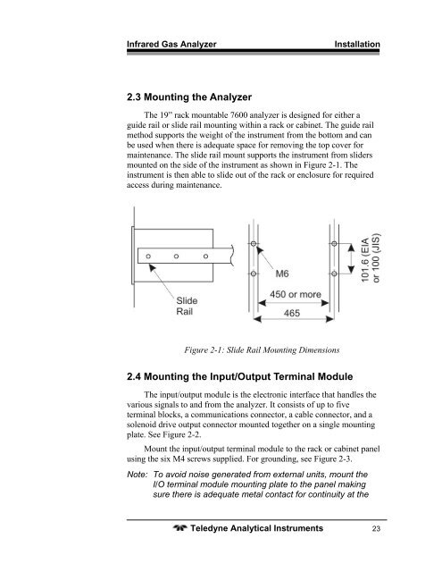
Infrared Gas AnalyzerInstallation2.3 Mounting the AnalyzerThe 19” rack mountable <strong>7600</strong> analyzer is designed for either aguide rail or slide rail mounting within a rack or cabinet. The guide railmethod supports the weight of the instrument from the bottom and canbe used when there is adequate space for removing the top cover formaintenance. The slide rail mount supports the instrument from slidersmounted on the side of the instrument as shown in Figure 2-1. Theinstrument is then able to slide out of the rack or enclosure for requiredaccess during maintenance.Figure 2-1: Slide Rail Mounting Dimensions2.4 Mounting the Input/Output Terminal ModuleThe input/output module is the electronic interface that handles thevarious signals to and from the analyzer. It consists of up to fiveterminal blocks, a communications connector, a cable connector, and asolenoid drive output connector mounted together on a single mountingplate. See Figure 2-2.Mount the input/output terminal module to the rack or cabinet panelusing the six M4 screws supplied. For grounding, see Figure 2-3.Note: To avoid noise generated from external units, mount theI/O terminal module mounting plate to the panel makingsure there is adequate metal contact for continuity at the<strong>Teledyne</strong> <strong>Analytical</strong> <strong>Instruments</strong> 23