EventsSeptember 2002Rhode Island, Warwick4th thru 8th, 22nd Annual National NarrowGauge Convention, Crowne Plaza Hotel at theCrossings, 801 Greenwich Ave (401/732-6000; $119/night). Trade show (all <strong>scale</strong>s),clinics, contests, etc. Info: 22nd National NarrowGauge Convention, P.O.Box 80573, So.Dartmouth, MA. 02748; (508) 996-0174;Email[JEB143@AOL.COM] or[http://www.22ndnngc.com/]Florida, Sarasota7th & 8th, Florida O Scalers Meet — 2 railonly — Sponsored by the Sarasota ModelRailroad Club, Ramada Inn Airport, 8440North Tamiami Trail, Sarasota, FL 34243, 1-941-355-7771, toll free 1-888-420-9704,room rate: $70.80. Features display andsales tables, door prizes, model contest, clinics,Florida O Scalers modular layout, SMRCClub layout. Advance registration fee of$25.00 includes Saturday lunch buffet andone six foot table. Contact Allen Novak, P.O.Box 1667, Tallevast, FL 34270-1667,anovak@ringling.edu, home: 941-351-9927,work 941-359-7583.Michigan, Holly7th & 8th, Detroit Model Railroad Club, Inc.Carrie Nation Open House, 104 N SaginawSt, Noon to 5:00 pm. Info: Edward MacDowell,DMRC, 104 N Saginaw St, Holly, MI48442; 248-634-5811.Indiana, Beech Grove (Indianapolis area)14th & 15th, Indianapolis Midwest O ScaleFall Meet, Holiday inn, 5120 Victory Dr. OScale, Proto:48, On3, On2, O Trolley/Tractiondisplays and sale. INFO: Jim Canter, 1203Rotherham Ln, Beech Grove, IN 46107-3323;317-888-8884; email [jcanternkp@aol.com].Oregon, Portland21st, 1st Pacific Northwest O Scale Meet (2-Rail & 3-Rail O Scale) hosted by the OregonO Scalers at St. John’s Episcopal Church,2036 SE Jefferson - This is an exclusively an O<strong>scale</strong> event with 2 and 3-rail’ers welcome.Includes layout tours, a silent auction, clinics,train videos and dinner. - Fri 3 pm to 6 pm;Sat 9 am to 6 pm, dinner 6 pm; $12 advanceregistration, $15 at door. Info:Dick Bublitz,12803 NE 100th St, Vancouver WA 98682;email [rsbublitz@attbi.com].New Jersey, Merchantville28th, Cherry Valley Model Railroad ClubAnnual Fall O Scale Only Train Meet - GraceEpiscopal Church, Maple Ave & Center St - 9am to 1:30 pm; $4, spouse & kids under 14free; 1st table $16 (includes 1 admission),additional tables $12 each. Info: Cherry ValleyModel Railroad Club, PO Box 192, MapleShade, NJ 08052; Chuck Jacobs (856) 234-1898 or Dave Richter (215) 639-7290.October 2002Oklahoma, Oklahoma City4th & 5th, Southwest O Scale Meet at OklahomaCity Community College, 7777 S MayAve., Oklahoma City, OK, Hotel: Ramada Limited- Reservations: (405) 682-2211, Fri: 1:00pm to 4:00 pm. Sat: 9:00 am to 4:00 pm.Info: George Wallace, 11937 Stratford Dr,Oklahoma City, OK 73120, (405) 751- 7649,Email [THUDCHIEF1@aol.com].Illinois, Vernon Hills11th, 6:30PM - 9:30 PM, (Doors open at5:30 PM for seller setup), Villa Park VFW Hall,39 E. St. Charles Rd. Villa Park, IL 60181(Located 1 mile west of IL Rt. 83 on St. CharlesRd.) Sponsored by the Prairie Scale ModelRailroaders. Admission: $4.00 (Spouses &Kids under 12 free with paying adult). Tables:$10.00 (One admission included with tablepurchase). Please limit items for sale to <strong>scale</strong>model railroad and railroad related items (NOLIONEL/TINPLATE). For more information or toreserve a table: Call: 847-702-0811 (leavemessage) or E-mail: info@psmr.orgMassachusetts, Gardner12th, Southern New England Model RR ClubO Scale Train Show, featuring 20’ x 70’ DCCOperating O <strong>scale</strong> layout. United MethodistChurch, 161 Chestnut St. 9:30 AM - 4:00 PM.Admission $5, Family Maximum $8. DealerTables: Before Labor Day, $15 (6 foot) and$20 (8 foot); After Labor Day, $20 (6 foot)and $25 (8 foot). Info: Bob Jones, 860-774-8622; P.O. Box 272, Ballouville CT 06233-0272, e-mail: bjmodels@neca.com, Web Site:www.snemrr.orgMaryland, Timonium12th & 13th, Double Show: The Great ScaleModel Train Show & The All-American High-Rail & Collectors Show, Maryland State Fairgrounds- 3 acres of <strong>trains</strong> separated intosections, Scale (by gauge) and Hi-Rail. Sevenhundred plus tables in the Scale area; 500tables available in the Hi-Rail/Tinplate section.The Harrisburg O Scalers will have their displaythere.November 2002Pennsylvania, Wind Gap2nd, Eastern O Scalers Swap Meet, PlainfieldFire Hall, 6480 Sullivan Trail, 9:00 am to 1:00pm. Info: EOS, PO Box 1781, Bensalem, PA19020; 215-639-3864; [www.EasternOScalers.com].Illinois, Rockford2nd & 3rd, 9th Annual Midway Village &Museum Center Model Train Show, 6799 GuilfordRd, Noon to 5:00 pm. Info: 815-397-9112; email [Fsm1019@aol.com].Ohio, Strongsville16th, Annual Western Reserve O Scale Meet,Holiday Inn Select, Strongsville (one exit southof turnpike on I-71 and Ohio Route 82), 9:00am to 3:00 pm. Info: Bob Boeddener, 32165Hickory Ln, Avon Lake, OH 44012; 440-933-7169.December 2002New Jersey, Pleasantville7th, 2-Rail O Scale Train Show sponsored bythe Tuckahoe O Scalers at the EpiphanyLutheran Church Hall, Franklin Blvd & TunisAve - Sale 10 am to 4 pm; Clinics; $3, family$5; tables $15 for 1st table, $12 for eachadditional table (supports O Scale Layout Projectat nearby Tuckahoe Railroad Museum;dealers checks payable to John P. Dunn, Sr.).Info: John P. Dunn, Sr, 38 E Revere Ave,Northfield, NJ 08225; (609) 484-8125; email[JDUNN8888@aol.com].Advertisers IndexAndersen’s Train Station 14AtlasO 36BTS 43Central Locomotive Works 14Chicagoland 10Get Real Productions 45Jim Hackworth Model Trains 45Harry Hieke 45HomaBed 14InterMountain 27Mickeys Model Works 22NCE Corp 43Norm’s O Scale 36O Scale Kings 39O Scale Realty 17Overland Models 15P&D Hobby Shop 10Pecos River BrassBCPrecision Scale Models IBCPRR Brass 17Public Delivery Track 31Red Caboose 33Rons Books 41Rich Yoder ModelsIFCRuss Briggs Design 17SGL Lines 33Stevenson Preservation Lines 17Sunset Models Inc. 35T Bone Models 17Tom Thorpe Curved Benchwork 1046 • O Scale Trains
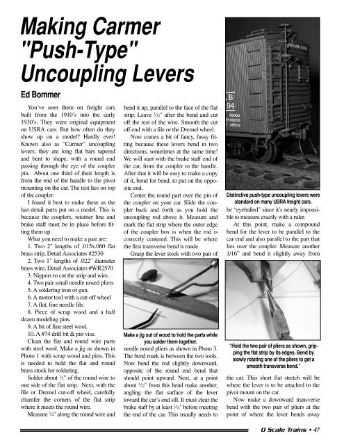
Making Carmer"Push-Type"Uncoupling LeversEd BommerYou’ve seen them on freight carsbuilt from the 1910’s into the early1930’s. They were original equipmenton USRA cars. But how often do theyshow up on a model? Hardly ever!Known also as “Carmer” uncouplinglevers, they are long flat bars taperedand bent to shape, with a round endpassing through the eye of the couplerpin. About one third of their length isfrom the end of the handle to the pivotmounting on the car. The rest lies on topof the coupler.I found it best to make these as thelast detail parts put on a model. This isbecause the couplers, retainer line andbrake staff must be in place before fittingthem up.What you need to make a pair are:1. Two 2" lengths of .015x.060 flatbrass strip, Detail Associates #25302. Two 1" lengths of .022" diameterbrass wire, Detail Associates #WR25703. Nippers to cut the strip and wire.4. Two pair small needle nosed pliers5. A soldering iron or gun.6. A motor tool with a cut-off wheel7. A flat, fine needle file.8. Piece of scrap wood and a halfdozen modeling pins.9. A bit of fine steel wool.10. A #74 drill bit & pin vise.Clean the flat and round wire partswith steel wool. Make a jig as shown inPhoto 1 with scrap wood and pins. Thisis needed to hold the flat and roundbrass stock for soldering.Solder about 1 ⁄2" of the round wire toone side of the flat strip. Next, with thefile or Dremel cut-off wheel, carefullychamfer the corners of the flat stripwhere it meets the round wire.Measure 1 ⁄4" along the round wire andbend it up, parallel to the face of the flatstrip. Leave 1 ⁄32" after the bend and cutoff the rest of the wire. Smooth the cutoff end with a file or the Dremel wheel.Now comes a bit of fancy, fussy fittingbecause these levers bend in twodirections, sometimes at the same time!We will start with the brake staff end ofthe car, from the coupler to the handle.After that it will be easy to make a copyof it, bend for bend, to put on the oppositeend.Center the round part over the pin ofthe coupler on your car. Slide the couplerback and forth as you hold theuncoupling rod above it. Measure andmark the flat strip where the outer edgeof the coupler box is when the rod iscorrectly centered. This will be wherethe first transverse bend is made.Grasp the lever stock with two pair ofMake a jig out of wood to hold the parts whileyou solder them together.needle nosed pliers as shown in Photo 3.The bend mark is between the two tools.Now bend the rod slightly downward,opposite of the round end bend thatshould point upward. Next, at a pointabout 1 ⁄32" from this bend make another,angling the flat surface of the levertoward the car’s end sill. It must clear thebrake staff by at least 1 ⁄32" before meetingthe end of the car. This usually needs toDistinctive push-type uncoupling levers werestandard on many USRA freight cars.be “eyeballed” since it’s nearly impossibleto measure exactly with a ruler.At this point, make a compoundbend for the lever to be parallel to thecar end and also parallel to the part thatlies over the coupler. Measure another1/16” and bend it slightly away from“Hold the two pair of pliers as shown, grippingthe flat strip by its edges. Bend byslowly rotating one of the pliers to get asmooth transverse bend.”the car. This short flat stretch will bewhere the lever is to be attached to thepivot mount on the car.Now make a downward transversebend with the two pair of pliers at thepoint of where the lever bends awayO Scale Trains • 47