CCC and TCC - Juniper Networks
CCC and TCC - Juniper Networks
CCC and TCC - Juniper Networks

You also want an ePaper? Increase the reach of your titles
YUMPU automatically turns print PDFs into web optimized ePapers that Google loves.
Junos ® OS<strong>CCC</strong> <strong>and</strong> <strong>TCC</strong>Release11.4Published: 2011-11-08Revision 1Copyright © 2011, <strong>Juniper</strong> <strong>Networks</strong>, Inc.
<strong>Juniper</strong> <strong>Networks</strong>, Inc.1194 North Mathilda AvenueSunnyvale, California 94089USA408-745-2000www.juniper.netThis product includes the Envoy SNMP Engine, developed by Epilogue Technology, an Integrated Systems Company. Copyright © 1986-1997,Epilogue Technology Corporation. All rights reserved. This program <strong>and</strong> its documentation were developed at private expense, <strong>and</strong> no partof them is in the public domain.This product includes memory allocation software developed by Mark Moraes, copyright © 1988, 1989, 1993, University of Toronto.This product includes FreeBSD software developed by the University of California, Berkeley, <strong>and</strong> its contributors. All of the documentation<strong>and</strong> software included in the 4.4BSD <strong>and</strong> 4.4BSD-Lite Releases is copyrighted by the Regents of the University of California. Copyright ©1979, 1980, 1983, 1986, 1988, 1989, 1991, 1992, 1993, 1994. The Regents of the University of California. All rights reserved.GateD software copyright © 1995, the Regents of the University. All rights reserved. Gate Daemon was originated <strong>and</strong> developed throughrelease 3.0 by Cornell University <strong>and</strong> its collaborators. Gated is based on Kirton’s EGP, UC Berkeley’s routing daemon (routed), <strong>and</strong> DCN’sHELLO routing protocol. Development of Gated has been supported in part by the National Science Foundation. Portions of the GateDsoftware copyright © 1988, Regents of the University of California. All rights reserved. Portions of the GateD software copyright © 1991, D.L. S. Associates.This product includes software developed by Maker Communications, Inc., copyright © 1996, 1997, Maker Communications, Inc.<strong>Juniper</strong> <strong>Networks</strong>, Junos, Steel-Belted Radius, NetScreen, <strong>and</strong> ScreenOS are registered trademarks of <strong>Juniper</strong> <strong>Networks</strong>, Inc. in the UnitedStates <strong>and</strong> other countries. The <strong>Juniper</strong> <strong>Networks</strong> Logo, the Junos logo, <strong>and</strong> JunosE are trademarks of <strong>Juniper</strong> <strong>Networks</strong>, Inc. All othertrademarks, service marks, registered trademarks, or registered service marks are the property of their respective owners.<strong>Juniper</strong> <strong>Networks</strong> assumes no responsibility for any inaccuracies in this document. <strong>Juniper</strong> <strong>Networks</strong> reserves the right to change, modify,transfer, or otherwise revise this publication without notice.Products made or sold by <strong>Juniper</strong> <strong>Networks</strong> or components thereof might be covered by one or more of the following patents that areowned by or licensed to <strong>Juniper</strong> <strong>Networks</strong>: U.S. Patent Nos. 5,473,599, 5,905,725, 5,909,440, 6,192,051, 6,333,650, 6,359,479, 6,406,312,6,429,706, 6,459,579, 6,493,347, 6,538,518, 6,538,899, 6,552,918, 6,567,902, 6,578,186, <strong>and</strong> 6,590,785.Junos ® OS <strong>CCC</strong> <strong>and</strong> T<strong>CCC</strong>opyright © 2011, <strong>Juniper</strong> <strong>Networks</strong>, Inc.All rights reserved.Revision HistoryOctober 2011—Revision 1; initial releaseThe information in this document is current as of the date listed in the revision history.END USER LICENSE AGREEMENTThe <strong>Juniper</strong> <strong>Networks</strong> product that is the subject of this technical documentation consists of (or is intended for use with) <strong>Juniper</strong> <strong>Networks</strong>software. Use of such software is subject to the terms <strong>and</strong> conditions of the End User License Agreement (“EULA”) posted athttp://www.juniper.net/support/eula.html. By downloading, installing or using such software, you agree to the terms <strong>and</strong> conditionsof that EULA.iiCopyright © 2011, <strong>Juniper</strong> <strong>Networks</strong>, Inc.
Table of ContentsPart 1OverviewChapter 1 Introduction to <strong>CCC</strong> <strong>and</strong> <strong>TCC</strong> . . . . . . . . . . . . . . . . . . . . . . . . . . . . . . . . . . . . . . . . 3<strong>CCC</strong> Overview . . . . . . . . . . . . . . . . . . . . . . . . . . . . . . . . . . . . . . . . . . . . . . . . . . . . . . . 3Transmitting Nonst<strong>and</strong>ard BPDUs . . . . . . . . . . . . . . . . . . . . . . . . . . . . . . . . . . . . . . 4<strong>TCC</strong> Overview . . . . . . . . . . . . . . . . . . . . . . . . . . . . . . . . . . . . . . . . . . . . . . . . . . . . . . . 4<strong>CCC</strong> <strong>and</strong> <strong>TCC</strong> Graceful Restart . . . . . . . . . . . . . . . . . . . . . . . . . . . . . . . . . . . . . . . . . 5Part 2ConfigurationChapter 2 <strong>CCC</strong> <strong>and</strong> <strong>TCC</strong> Configuration Guidelines . . . . . . . . . . . . . . . . . . . . . . . . . . . . . . . 9Configuring Layer 2 Switching Cross-Connects Using <strong>CCC</strong> . . . . . . . . . . . . . . . . . . . 9Configuring the <strong>CCC</strong> Encapsulation for Layer 2 SwitchingCross-Connects . . . . . . . . . . . . . . . . . . . . . . . . . . . . . . . . . . . . . . . . . . . . . 10Configuring ATM Encapsulation for Layer 2 SwitchingCross-Connects . . . . . . . . . . . . . . . . . . . . . . . . . . . . . . . . . . . . . . . . . . 10Configuring Ethernet Encapsulation for Layer 2 SwitchingCross-Connects . . . . . . . . . . . . . . . . . . . . . . . . . . . . . . . . . . . . . . . . . . 11Configuring Ethernet VLAN Encapsulation for Layer 2 SwitchingCross-Connects . . . . . . . . . . . . . . . . . . . . . . . . . . . . . . . . . . . . . . . . . . 11Configuring Aggregated Ethernet Encapsulation for Layer 2 SwitchingCross-Connects . . . . . . . . . . . . . . . . . . . . . . . . . . . . . . . . . . . . . . . . . . 12Configuring Frame Relay Encapsulation for Layer 2 SwitchingCross-Connects . . . . . . . . . . . . . . . . . . . . . . . . . . . . . . . . . . . . . . . . . . 13Configuring PPP <strong>and</strong> Cisco HDLC Encapsulation for Layer 2 SwitchingCross-Connects . . . . . . . . . . . . . . . . . . . . . . . . . . . . . . . . . . . . . . . . . . 14Configuring the <strong>CCC</strong> Connection for Layer 2 Switching Cross-Connects . . . . 14Configuring MPLS for Layer 2 Switching Cross-Connects . . . . . . . . . . . . . . . . 14Example: Configuring a Layer 2 Switching Cross-Connect . . . . . . . . . . . . . . . 15Configuring MPLS LSP Tunnel Cross-Connects Using <strong>CCC</strong> . . . . . . . . . . . . . . . . . . . 17Configuring the <strong>CCC</strong> Encapsulation for LSP Tunnel Cross-Connects . . . . . . . 18Configuring the <strong>CCC</strong> Connection for LSP Tunnel Cross-Connects . . . . . . . . . 19Example: Configuring an LSP Tunnel Cross-Connect . . . . . . . . . . . . . . . . . . . 20Configuring LSP Stitching Cross-Connects Using <strong>CCC</strong> . . . . . . . . . . . . . . . . . . . . . . 21Example: Configuring an LSP Stitching Cross-Connect . . . . . . . . . . . . . . . . . 22Configuring <strong>TCC</strong> . . . . . . . . . . . . . . . . . . . . . . . . . . . . . . . . . . . . . . . . . . . . . . . . . . . . 22Configuring the Encapsulation for Layer 2 Switching <strong>TCC</strong>s . . . . . . . . . . . . . . . 23Configuring PPP <strong>and</strong> Cisco HDLC Encapsulation for Layer 2 Switching<strong>TCC</strong>s . . . . . . . . . . . . . . . . . . . . . . . . . . . . . . . . . . . . . . . . . . . . . . . . . . 23Configuring ATM Encapsulation for Layer 2 Switching <strong>TCC</strong>s . . . . . . . . . . 23Configuring Frame Relay Encapsulation for Layer 2 Switching <strong>TCC</strong>s . . . 24Copyright © 2011, <strong>Juniper</strong> <strong>Networks</strong>, Inc.iii
<strong>CCC</strong> <strong>and</strong> T<strong>CCC</strong>onfiguring Ethernet Encapsulation for Layer 2 Switching <strong>TCC</strong>s . . . . . . . 24Configuring Ethernet Extended VLAN Encapsulation for Layer 2Switching <strong>TCC</strong>s . . . . . . . . . . . . . . . . . . . . . . . . . . . . . . . . . . . . . . . . . . 25Configuring ARP for Ethernet <strong>and</strong> Ethernet Extended VLANEncapsulations . . . . . . . . . . . . . . . . . . . . . . . . . . . . . . . . . . . . . . . . . . 26Configuring the Connection for Layer 2 Switching <strong>TCC</strong>s . . . . . . . . . . . . . . . . . 26Configuring MPLS for Layer 2 Switching <strong>TCC</strong>s . . . . . . . . . . . . . . . . . . . . . . . . . 27Configuring <strong>CCC</strong> <strong>and</strong> <strong>TCC</strong> Graceful Restart . . . . . . . . . . . . . . . . . . . . . . . . . . . . . . . 27Configuring <strong>CCC</strong> Switching for Point-to-Multipoint LSPs . . . . . . . . . . . . . . . . . . . 28Configuring the Point-to-Multipoint LSP Switch on Ingress PE Routers . . . . 28Configuring the Point-to-Multipoint LSP Switch on Egress PE Routers . . . . . 29Part 3AdministrationChapter 3 Summary of <strong>CCC</strong> <strong>and</strong> <strong>TCC</strong> Configuration Statements . . . . . . . . . . . . . . . . . . 33connections . . . . . . . . . . . . . . . . . . . . . . . . . . . . . . . . . . . . . . . . . . . . . . . . . . . . . . . 34encapsulation (Logical Interface) . . . . . . . . . . . . . . . . . . . . . . . . . . . . . . . . . . . . . . 35encapsulation (Physical Interface) . . . . . . . . . . . . . . . . . . . . . . . . . . . . . . . . . . . . . 37interface-switch . . . . . . . . . . . . . . . . . . . . . . . . . . . . . . . . . . . . . . . . . . . . . . . . . . . . 39lsp-switch . . . . . . . . . . . . . . . . . . . . . . . . . . . . . . . . . . . . . . . . . . . . . . . . . . . . . . . . 40p2mp-receive-switch . . . . . . . . . . . . . . . . . . . . . . . . . . . . . . . . . . . . . . . . . . . . . . . . 41p2mp-transmit-switch . . . . . . . . . . . . . . . . . . . . . . . . . . . . . . . . . . . . . . . . . . . . . . 42remote-interface-switch . . . . . . . . . . . . . . . . . . . . . . . . . . . . . . . . . . . . . . . . . . . . . 43Part 4IndexIndex . . . . . . . . . . . . . . . . . . . . . . . . . . . . . . . . . . . . . . . . . . . . . . . . . . . . . . . . . . . . . 47ivCopyright © 2011, <strong>Juniper</strong> <strong>Networks</strong>, Inc.
List of FiguresPart 1OverviewChapter 1 Introduction to <strong>CCC</strong> <strong>and</strong> <strong>TCC</strong> . . . . . . . . . . . . . . . . . . . . . . . . . . . . . . . . . . . . . . . . 3Figure 1: <strong>TCC</strong> Example . . . . . . . . . . . . . . . . . . . . . . . . . . . . . . . . . . . . . . . . . . . . . . . . 4Figure 2: Remote Interface Switch Connecting Two CE Routers Using <strong>CCC</strong> . . . . . . 5Part 2ConfigurationChapter 2 <strong>CCC</strong> <strong>and</strong> <strong>TCC</strong> Configuration Guidelines . . . . . . . . . . . . . . . . . . . . . . . . . . . . . . . 9Figure 3: Layer 2 Switching Cross-Connect . . . . . . . . . . . . . . . . . . . . . . . . . . . . . . . . 9Figure 4: Topology of a Frame Relay Layer 2 Switching Cross-Connect . . . . . . . . . 15Figure 5: Sample Topology of a VLAN Layer 2 Switching Cross-Connect . . . . . . . 16Figure 6: MPLS Tunnel Cross-Connect . . . . . . . . . . . . . . . . . . . . . . . . . . . . . . . . . . . 17Figure 7: Example Topology of MPLS LSP Tunnel Cross-Connect . . . . . . . . . . . . . 20Figure 8: LSP Stitching Cross-Connect . . . . . . . . . . . . . . . . . . . . . . . . . . . . . . . . . . 21Figure 9: Example Topology of LSP Stitching Cross-Connect . . . . . . . . . . . . . . . . 22Copyright © 2011, <strong>Juniper</strong> <strong>Networks</strong>, Inc.v
<strong>CCC</strong> <strong>and</strong> <strong>TCC</strong>viCopyright © 2011, <strong>Juniper</strong> <strong>Networks</strong>, Inc.
PART 1Overview• Introduction to <strong>CCC</strong> <strong>and</strong> <strong>TCC</strong> on page 3Copyright © 2011, <strong>Juniper</strong> <strong>Networks</strong>, Inc.1
<strong>CCC</strong> <strong>and</strong> <strong>TCC</strong>2Copyright © 2011, <strong>Juniper</strong> <strong>Networks</strong>, Inc.
CHAPTER 1Introduction to <strong>CCC</strong> <strong>and</strong> T<strong>CCC</strong>CC Overview• <strong>CCC</strong> Overview on page 3• Transmitting Nonst<strong>and</strong>ard BPDUs on page 4• <strong>TCC</strong> Overview on page 4• <strong>CCC</strong> <strong>and</strong> <strong>TCC</strong> Graceful Restart on page 5Circuit cross-connect (<strong>CCC</strong>) allows you to configure transparent connections betweentwo circuits, where a circuit can be a Frame Relay data-link connection identifier (DLCI),an Asynchronous Transfer Mode (ATM) virtual circuit (VC), a Point-to-Point Protocol(PPP) interface, a Cisco High-Level Data Link Control (HDLC) interface, or an MPLSlabel-switched path (LSP). Using <strong>CCC</strong>, packets from the source circuit are delivered tothe destination circuit with, at most, the Layer 2 address being changed. No otherprocessing—such as header checksums, time-to-live (TTL) decrementing, or protocolprocessing—is done.<strong>CCC</strong> circuits fall into two categories: logical interfaces, which include DLCIs, VCs, virtuallocal area network (VLAN) IDs, PPP <strong>and</strong> Cisco HDLC interfaces, <strong>and</strong> LSPs. The two circuitcategories provide three types of cross-connect:• Layer 2 switching—Cross-connects between logical interfaces provide what is essentiallyLayer 2 switching. The interfaces that you connect must be of the same type.• MPLS tunneling—Cross-connects between interfaces <strong>and</strong> LSPs allow you to connecttwo distant interface circuits of the same type by creating MPLS tunnels that use LSPsas the conduit.• LSP stitching—Cross-connects between LSPs provide a way to “stitch” together twolabel-switched paths, including paths that fall in two different traffic engineeringdatabase areas.For Layer 2 switching <strong>and</strong> MPLS tunneling, the cross-connect is bidirectional, so packetsreceived on the first interface are transmitted out the second interface, <strong>and</strong> those receivedon the second interface are transmitted out the first. For LSP stitching, the cross-connectis unidirectional.You can police (control) the amount of traffic flowing over <strong>CCC</strong> circuits. For moreinformation, see the Junos OS VPNs Configuration Guide.Copyright © 2011, <strong>Juniper</strong> <strong>Networks</strong>, Inc.3
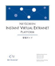
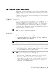
<strong>CCC</strong> <strong>and</strong> <strong>TCC</strong>It is also possible to use the ping comm<strong>and</strong> to check the integrity of <strong>CCC</strong> LSPs. See Pinging<strong>CCC</strong> LSPs for more information.Transmitting Nonst<strong>and</strong>ard BPDUs<strong>CCC</strong> protocol (<strong>and</strong> Layer 2 Circuit <strong>and</strong> Layer 2 VPN) configurations can transmitnonst<strong>and</strong>ard bridge protocol data units (BPDUs) generated by other vendors’ equipment.This is the default behavior on all supported PICs <strong>and</strong> requires no additional configuration.The following PICs are supported on M320 <strong>and</strong> T Series routers:• 1-port Gigabit Ethernet PIC• 2-port Gigabit Ethernet PIC• 4-port Gigabit Ethernet PIC• 10-port Gigabit Ethernet PIC<strong>TCC</strong> OverviewTranslational cross-connect (<strong>TCC</strong>) is a switching concept that enables you to establishinterconnections between a variety of Layer 2 protocols or circuits. It is similar to <strong>CCC</strong>.However, whereas <strong>CCC</strong> requires the same Layer 2 encapsulations on each side of a <strong>Juniper</strong><strong>Networks</strong> router (such as PPP-to-PPP or Frame Relay-to-Frame Relay), <strong>TCC</strong> enablesyou to connect different types of Layer 2 protocols interchangeably. When you use <strong>TCC</strong>,combinations such as PPP-to-ATM (see Figure 1 on page 4) <strong>and</strong> Ethernet-to-FrameRelay connections are possible.Figure 1: <strong>TCC</strong> ExampleThe Layer 2 circuits <strong>and</strong> encapsulation types that can be interconnected by <strong>TCC</strong> are:• Ethernet• Extended VLANs• PPP• HDLC• ATM• Frame Relay<strong>TCC</strong> works by removing the Layer 2 header when frames enter the router <strong>and</strong> adding adifferent Layer 2 header on the frames before they leave the router. In Figure 1 on page 4,the PPP encapsulation is stripped from the frames arriving at Router B, <strong>and</strong> the ATMencapsulation is added before the frames are sent to Router C.4Copyright © 2011, <strong>Juniper</strong> <strong>Networks</strong>, Inc.
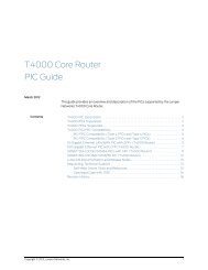
Introduction to <strong>CCC</strong> <strong>and</strong> T<strong>CCC</strong>CC <strong>and</strong> <strong>TCC</strong> Graceful RestartNote that all control traffic is terminated at the interconnecting router (Router B).Examples of traffic controllers include the Link Control Protocol (LCP) <strong>and</strong> the NetworkControl Protocol (NCP) for PPP, keepalives for HDLC, <strong>and</strong> Local Management Interface(LMI) for Frame Relay.<strong>TCC</strong> functionality is different from st<strong>and</strong>ard Layer 2 switching. <strong>TCC</strong> only swaps Layer 2headers. No other processing, such as header checksums, TTL decrementing, or protocolh<strong>and</strong>ling is performed. <strong>TCC</strong> is supported for IPv4 only.Address Resolution Protocol (APR) packet policing on <strong>TCC</strong> Ethernet interfaces is effectivefor releases 10.4 <strong>and</strong> onwards.You can configure <strong>TCC</strong> for interface switching <strong>and</strong> for Layer 2 VPNs. For more informationabout using <strong>TCC</strong> for virtual private networks (VPNs), see the Junos OS VPNs ConfigurationGuide.<strong>CCC</strong> <strong>and</strong> <strong>TCC</strong> graceful restart allows Layer 2 connections between customer edge (CE)routers to restart gracefully. These Layer 2 connections are configured with theremote-interface-switch or lsp-switch statements. Because these <strong>CCC</strong> <strong>and</strong> <strong>TCC</strong>connections have an implicit dependency on RSVP LSPs, graceful restart for <strong>CCC</strong> <strong>and</strong><strong>TCC</strong> uses the RSVP graceful restart capabilities.RSVP graceful restart must be enabled on the PE routers <strong>and</strong> P routers to enable gracefulrestart for <strong>CCC</strong> <strong>and</strong> <strong>TCC</strong>. Also, because RSVP is used as the signaling protocol for signalinglabel information, the neighboring router must use helper mode to assist with the RSVPrestart procedures.Figure 2 on page 5 illustrates how graceful restart might work on a <strong>CCC</strong> connectionbetween two CE routers.Figure 2: Remote Interface Switch Connecting Two CE Routers Using <strong>CCC</strong>PE Router A is the ingress for the transmit LSP from PE Router A to PE Router B <strong>and</strong> theegress for the receive LSP from PE Router B to PE Router A. With RSVP graceful restartenabled on all the PE <strong>and</strong> P routers, the following occurs when PE router A restarts:• PE Router A preserves the forwarding state associated with the <strong>CCC</strong> routes (thosefrom <strong>CCC</strong> to MPLS <strong>and</strong> from MPLS to <strong>CCC</strong>).Copyright © 2011, <strong>Juniper</strong> <strong>Networks</strong>, Inc.5
<strong>CCC</strong> <strong>and</strong> <strong>TCC</strong>• Traffic flows without disruption from CE router to CE router.• After the restart, PE Router A preserves the label for the LSP for which PE Router A isthe egress (the receive LSP, for example). The transmit LSP from PE Router A to PERouter B can derive new label mappings, but should not cause any traffic disruption.6Copyright © 2011, <strong>Juniper</strong> <strong>Networks</strong>, Inc.
PART 2Configuration• <strong>CCC</strong> <strong>and</strong> <strong>TCC</strong> Configuration Guidelines on page 9Copyright © 2011, <strong>Juniper</strong> <strong>Networks</strong>, Inc.7
<strong>CCC</strong> <strong>and</strong> <strong>TCC</strong>8Copyright © 2011, <strong>Juniper</strong> <strong>Networks</strong>, Inc.
CHAPTER 2<strong>CCC</strong> <strong>and</strong> <strong>TCC</strong> Configuration Guidelines• Configuring Layer 2 Switching Cross-Connects Using <strong>CCC</strong> on page 9• Configuring MPLS LSP Tunnel Cross-Connects Using <strong>CCC</strong> on page 17• Configuring LSP Stitching Cross-Connects Using <strong>CCC</strong> on page 21• Configuring <strong>TCC</strong> on page 22• Configuring <strong>CCC</strong> <strong>and</strong> <strong>TCC</strong> Graceful Restart on page 27• Configuring <strong>CCC</strong> Switching for Point-to-Multipoint LSPs on page 28Configuring Layer 2 Switching Cross-Connects Using <strong>CCC</strong>Layer 2 switching cross-connects join logical interfaces to form what is essentially Layer 2switching. The interfaces that you connect must be of the same type.Figure 3 on page 9 illustrates a Layer 2 switching cross-connect. In this topology, Router A<strong>and</strong> Router C have Frame Relay connections to Router B, which is a <strong>Juniper</strong> <strong>Networks</strong>router. Circuit cross-connect (<strong>CCC</strong>) allows you to configure Router B to act as a FrameRelay (Layer 2) switch.To configure Router B to act as a Frame Relay switch, you configure a circuit from Router Ato Router C that passes through Router B, effectively configuring Router B as a FrameRelay switch with respect to these routers. This configuration allows Router B totransparently switch packets (frames) between Router A <strong>and</strong> Router C without regardto the packets’ contents or the Layer 3 protocols. The only processing that Router Bperforms is to translate DLCI 600 to 750.Figure 3: Layer 2 Switching Cross-ConnectIf the Router A–to–Router B <strong>and</strong> Router B–to–Router C circuits were PPP, for example,the Link Control Protocol <strong>and</strong> Network Control Protocol exchanges occur betweenRouter A <strong>and</strong> Router C. These messages are h<strong>and</strong>led transparently by Router B, allowingRouter A <strong>and</strong> Router C to use various PPP options (such as header or address compression<strong>and</strong> authentication) that Router B might not support. Similarly, Router A <strong>and</strong> Router Cexchange keepalives, providing circuit-to-circuit connectivity status.Copyright © 2011, <strong>Juniper</strong> <strong>Networks</strong>, Inc.9
<strong>CCC</strong> <strong>and</strong> <strong>TCC</strong>You can configure Layer 2 switching cross-connects on PPP, Cisco HDLC, Frame Relay,Ethernet, <strong>and</strong> ATM circuits. In a single cross-connect, only like interfaces can be connected.To configure Layer 2 switching cross-connects, you must configure the following on therouter that is acting as the switch (Router B in Figure 3 on page 9):• Configuring the <strong>CCC</strong> Encapsulation for Layer 2 Switching Cross-Connects on page 10• Configuring the <strong>CCC</strong> Connection for Layer 2 Switching Cross-Connects on page 14• Configuring MPLS for Layer 2 Switching Cross-Connects on page 14• Example: Configuring a Layer 2 Switching Cross-Connect on page 15Configuring the <strong>CCC</strong> Encapsulation for Layer 2 Switching Cross-ConnectsTo configure Layer 2 switching cross-connects, configure the <strong>CCC</strong> encapsulation on therouter that is acting as the switch (Router B in Figure 3 on page 9).NOTE: You cannot configure families on <strong>CCC</strong> interfaces; that is, you cannotinclude the family statement at the [edit interfaces interface-name unitlogical-unit-number] hierarchy level.For instructions for configuring the encapsulation for Layer 2 switching cross-connects,see the following sections:• Configuring ATM Encapsulation for Layer 2 Switching Cross-Connects on page 10• Configuring Ethernet Encapsulation for Layer 2 Switching Cross-Connects on page 11• Configuring Ethernet VLAN Encapsulation for Layer 2 SwitchingCross-Connects on page 11• Configuring Aggregated Ethernet Encapsulation for Layer 2 SwitchingCross-Connects on page 12• Configuring Frame Relay Encapsulation for Layer 2 SwitchingCross-Connects on page 13• Configuring PPP <strong>and</strong> Cisco HDLC Encapsulation for Layer 2 SwitchingCross-Connects on page 14Configuring ATM Encapsulation for Layer 2 Switching Cross-ConnectsFor ATM circuits, specify the encapsulation when configuring the virtual circuit (VC).Configure each VC as a circuit or a regular logical interface by including the followingstatements:at-fpc/pic/port {atm-options {vpi vpi-identifier maximum-vcs maximum-vcs;}unit logical-unit-number {point-to-point; # Default interface typeencapsulation encapsulation-type;vci vpi-identifier.vci-identifier;10Copyright © 2011, <strong>Juniper</strong> <strong>Networks</strong>, Inc.
<strong>CCC</strong> <strong>and</strong> <strong>TCC</strong> Configuration Guidelines}}You can include these statements at the following hierarchy levels:• [edit interfaces]• [edit logical-systems logical-system-name interfaces]Configuring Ethernet Encapsulation for Layer 2 Switching Cross-ConnectsFor Ethernet circuits, specify ethernet-ccc in the encapsulation statement. This statementconfigures the entire physical device. For these circuits to work, you must also configurea logical interface (unit 0).Ethernet interfaces with st<strong>and</strong>ard Tag Protocol Identifier (TPID) tagging can useEthernet <strong>CCC</strong> encapsulation. On M Series Multiservice Edge Routers, except the M320,one-port Gigabit Ethernet, two-port Gigabit Ethernet, four-port Gigabit Ethernet, <strong>and</strong>four-port Fast Ethernet PICs can use Ethernet <strong>CCC</strong> encapsulation. On T Series CoreRouters <strong>and</strong> M320 routers, one-port Gigabit Ethernet <strong>and</strong> two-port Gigabit Ethernet PICsinstalled in FPC2 can use Ethernet <strong>CCC</strong> encapsulation. When you use this encapsulationtype, you can configure the ccc family only.fe-fpc/pic/port {encapsulation ethernet-ccc;unit 0;}You can include these statements at the following hierarchy levels:• [edit interfaces]• [edit logical-systems logical-system-name interfaces]Configuring Ethernet VLAN Encapsulation for Layer 2 Switching Cross-ConnectsAn Ethernet virtual LAN (VLAN) circuit can be configured using either the vlan-ccc orextended-vlan-ccc encapsulation. If you configure the extended-vlan-ccc encapsulationon the physical interface, you cannot configure the inet family on the logical interfaces.Only the ccc family is allowed. If you configure the vlan-ccc encapsulation on the physicalinterface, both the inet <strong>and</strong> ccc families are supported on the logical interfaces. Ethernetinterfaces in VLAN mode can have multiple logical interfaces.For encapsulation type vlan-ccc, VLAN IDs from 512 through 4094 are reserved for <strong>CCC</strong>VLANs. For the extended-vlan-ccc encapsulation type, all VLAN IDs 1 <strong>and</strong> higher are valid.VLAN ID 0 is reserved for tagging the priority of frames.NOTE: Some vendors use the proprietary TPIDs 0x9100 <strong>and</strong> 0x9901 toencapsulate a VLAN-tagged packet into a VLAN-<strong>CCC</strong> tunnel to interconnecta geographically separated metro Ethernet network. By configuring theextended-vlan-ccc encapsulation type, a <strong>Juniper</strong> <strong>Networks</strong> router can acceptall three TPIDs (0x8100, 0x9100, <strong>and</strong> 0x9901).Copyright © 2011, <strong>Juniper</strong> <strong>Networks</strong>, Inc.11
<strong>CCC</strong> <strong>and</strong> T<strong>CCC</strong>onfigure an Ethernet VLAN circuit with the vlan-ccc encapsulation as follows:interfaces {type-fpc/pic/port {vlan-tagging;encapsulation vlan-ccc;unit logical-unit-number {encapsulation vlan-ccc;vlan-id vlan-id;}}}You can configure these statements at the following hierarchy levels:• [edit interfaces]• [edit logical-systems logical-system-name interfaces]Configure an Ethernet VLAN circuit with the extended-vlan-ccc encapsulation statementas follows:interfaces {type-fpc/pic/port {vlan-tagging;encapsulation extended-vlan-ccc;unit logical-unit-number {vlan-id vlan-id;family ccc;}}}You can configure these statements at the following hierarchy levels:• [edit interfaces]• [edit logical-systems logical-system-name interfaces]Whether you configure the encapsulation as vlan-ccc or extended-vlan-ccc, you mustenable VLAN tagging by including the vlan-tagging statement.Configuring Aggregated Ethernet Encapsulation for Layer 2 SwitchingCross-ConnectsYou can configure aggregated Ethernet interfaces for <strong>CCC</strong> connections <strong>and</strong> for Layer 2virtual private networks (VPNs).Aggregated Ethernet interfaces configured with VLAN tagging can be configured withmultiple logical interfaces. The only encapsulation available for aggregated Ethernetlogical interfaces is vlan-ccc. When you configure the vlan-id statement, you are limitedto VLAN IDs 512 through 4094.Aggregated Ethernet interfaces configured without VLAN tagging can be configured onlywith the ethernet-ccc encapsulation. All untagged Ethernet packets received are forwardedbased on the <strong>CCC</strong> parameters.12Copyright © 2011, <strong>Juniper</strong> <strong>Networks</strong>, Inc.
<strong>CCC</strong> <strong>and</strong> <strong>TCC</strong> Configuration GuidelinesTo configure aggregated Ethernet interfaces for <strong>CCC</strong> connections, include the ae0statement at the [edit interfaces] hierarchy level:[edit interfaces]ae0 {encapsulation (ethernet-ccc | extended-vlan-ccc | vlan-ccc);vlan-tagging;aggregated-ether-options {minimum-links links;link-speed speed;}unit logical-unit-number {encapsulation vlan-ccc;vlan-id identifier;family ccc;}}Be aware of the following limitations when configuring <strong>CCC</strong> connections over aggregatedEthernet interfaces:• If you configured load balancing between child links, be aware that a different hashkey is used to distribute packets among the child links. St<strong>and</strong>ard aggregated interfaceshave family inet configured. An IP version 4 (IPv4) hash key (based on the Layer 3information) is used to distribute packets among the child links. A <strong>CCC</strong> connectionover an aggregated Ethernet interface has family ccc configured instead. Instead ofan IPv4 hash key, an MPLS hash key (based on the destination media access control[MAC] address) is used to distributed packets among the child links.• The extended-vlan-ccc encapsulation is not supported on the 12-port Fast EthernetPIC <strong>and</strong> the 48-port Fast Ethernet PIC.• The Junos OS does not support the Link Aggregation Control Protocol (LACP) whenan aggregated interface is configured as a VLAN (with vlan-ccc encapsulation). LACPcan be configured only when the aggregated interface is configured with theethernet-ccc encapsulation.For more information about how to configure aggregated Ethernet interfaces, see theJunos OS Network Interfaces Configuration Guide.Configuring Frame Relay Encapsulation for Layer 2 Switching Cross-ConnectsFor Frame Relay circuits, specify the encapsulation when configuring the DLCI. Configureeach DLCI as a circuit or a regular logical interface. The DLCI for regular interfaces mustbe from 1 through 511. For <strong>CCC</strong> interfaces, it must be from 512 through 4094.interfaces {type-fpc/pic/port {unit logical-unit-number {point-to-point; # Default interface typeencapsulation encapsulation-type;dlci dlci-identifier;}}}Copyright © 2011, <strong>Juniper</strong> <strong>Networks</strong>, Inc.13
<strong>CCC</strong> <strong>and</strong> <strong>TCC</strong>You can configure these statements at the following hierarchy levels:• [edit interfaces]• [edit logical-systems logical-system-name interfaces]Configuring PPP <strong>and</strong> Cisco HDLC Encapsulation for Layer 2 SwitchingCross-ConnectsFor PPP <strong>and</strong> Cisco HDLC circuits, specify the encapsulation in the encapsulation statement.This statement configures the entire physical device. For these circuits to work, you mustconfigure a logical interface (unit 0).interfaces type-fpc/pic/port {encapsulation encapsulation-type;unit 0;}You can configure these statements at the following hierarchy levels:• [edit interfaces type-fpc/pic/port]• [edit logical-systems logical-system-name interfaces type-fpc/pic/port]Configuring the <strong>CCC</strong> Connection for Layer 2 Switching Cross-ConnectsTo configure Layer 2 switching cross-connects, define the connection between the twocircuits by including the interface-switch statement. You configure this connection onthe router that is acting as the switch (Router B in Figure 3 on page 9). The connectionjoins the interface that comes from the circuit’s source to the interface that leads to thecircuit’s destination. When you specify the interface names, include the logical portionof the name, which corresponds to the logical unit number. The cross-connect isbidirectional, so packets received on the first interface are transmitted out the secondinterface, <strong>and</strong> those received on the second interface are transmitted out the first.interface-switch connection-name {interface interface-name.unit-number;interface interface-name.unit-number;}You can include this statement at the following hierarchy levels:• [edit protocols connections]• [edit logical-systems logical-system-name protocols connections]Configuring MPLS for Layer 2 Switching Cross-ConnectsFor Layer 2 switching cross-connects to work, you must enable MPLS on the router byincluding at least the following statements. This minimum configuration enables MPLSon a logical interface for the switching cross-connect.Include the family mpls statement:family mpls;14Copyright © 2011, <strong>Juniper</strong> <strong>Networks</strong>, Inc.
<strong>CCC</strong> <strong>and</strong> <strong>TCC</strong> Configuration GuidelinesYou can configure this statement at the following hierarchy levels:• [edit interfaces interface-name unit logical-unit-number]• [edit logical-systems logical-system-name interfaces interface-name unitlogical-unit-number]You can then specify this logical interface in the MPLS protocol configuration:mpls {interface interface-name; # Required to enable MPLS on the interface}You can configure these statements at the following hierarchy levels:• [edit protocols]• [edit logical-systems logical-system-name protocols]Example: Configuring a Layer 2 Switching Cross-ConnectConfigure a full-duplex Layer 2 switching cross-connect between Router A <strong>and</strong> Router C,using a <strong>Juniper</strong> <strong>Networks</strong> router, Router B, as the virtual switch. See the topology in Figure4 on page 15 <strong>and</strong> Figure 5 on page 16.Figure 4: Topology of a Frame Relay Layer 2 Switching Cross-Connect[edit]interfaces {so-1/0/0 {encapsulation frame-relay-ccc;unit 1 {point-to-point;encapsulation frame-relay-ccc;dlci 600;}}so-2/0/0 {encapsulation frame-relay-ccc;unit 2 {point-to-point;encapsulation frame-relay-ccc;dlci 750;}}}protocols {connections {interface-switch router-a-to-router-c {interface so-1/0/0.1;Copyright © 2011, <strong>Juniper</strong> <strong>Networks</strong>, Inc.15
<strong>CCC</strong> <strong>and</strong> <strong>TCC</strong>interface so-2/0/0.2;}}mpls {interface all;}}Figure 5: Sample Topology of a VLAN Layer 2 Switching Cross-Connect[edit]interfaces {ge-2/1/0 {vlan-tagging;encapsulation vlan-ccc;unit 0 {encapsulation vlan-ccc;vlan-id 600;}}ge-2/2/0 {vlan-tagging;encapsulation vlan-ccc;unit 0 {encapsulation vlan-ccc;vlan-id 600;}unit 1 {family inet {vlan-id 1;address 10.9.200.1/24;}}}}protocols {mpls {interface all;}connections {interface-switch layer2-sw {interface ge-2/1/0.0;interface ge-2/2/0.0;}}}16Copyright © 2011, <strong>Juniper</strong> <strong>Networks</strong>, Inc.
<strong>CCC</strong> <strong>and</strong> <strong>TCC</strong> Configuration GuidelinesConfiguring MPLS LSP Tunnel Cross-Connects Using <strong>CCC</strong>MPLS tunnel cross-connects between interfaces <strong>and</strong> LSPs allow you to connect twodistant interface circuits of the same type by creating MPLS tunnels that use LSPs asthe conduit. The topology in Figure 6 on page 17 illustrates an MPLS LSP tunnelcross-connect. In this topology, two separate networks, in this case ATM access networks,are connected through an IP backbone. <strong>CCC</strong> allows you to establish an LSP tunnelbetween the two domains. With LSP tunneling, you tunnel the ATM traffic from onenetwork across a SONET backbone to the second network by using an MPLS LSP.Figure 6: MPLS Tunnel Cross-ConnectATM access networkIP BackboneATM access networkAATMVC 234<strong>Juniper</strong><strong>Networks</strong>router BLSP<strong>Juniper</strong><strong>Networks</strong>routerCATMVC 591Dg017093When traffic from Router A (VC 234) reaches Router B, it is encapsulated <strong>and</strong> placedinto an LSP, which is sent through the backbone to Router C. At Router C, the label isremoved, <strong>and</strong> the packets are placed onto the ATM permanent virtual circuit (PVC) (VC591) <strong>and</strong> sent to Router D. Similarly, traffic from Router D (VC 591) is sent over an LSPto Router B, then placed on VC 234 to Router A.You can configure LSP tunnel cross-connect on PPP, Cisco HDLC, Frame Relay, <strong>and</strong> ATMcircuits. In a single cross-connect, only like interfaces can be connected.When you use MPLS tunnel cross-connects to support IS-IS, you must ensure that theLSP’s maximum transmission unit (MTU) can, at a minimum, accommodate a 1492-octetIS-IS protocol data unit (PDU) in addition to the link-level overhead associated with thetechnology being connected.For the tunnel cross-connects to work, the IS-IS frame size on the edge routers (RoutersA <strong>and</strong> D in Figure 7 on page 20) must be smaller than the LSP’s MTU.NOTE: Frame size values do not include the frame check sequence (FCS) ordelimiting flags.To determine the LSP MTU required to support IS-IS, use the following calculation:IS-IS MTU (minimum 1492, default 1497) + frame overhead + 4 (MPLS shim header) =Minimum LSP MTUThe framing overhead varies based on the encapsulation being used. The following liststhe IS-IS encapsulation overhead values for various encapsulations:• ATM• AAL5 multiplex—8 bytes (RFC 1483)Copyright © 2011, <strong>Juniper</strong> <strong>Networks</strong>, Inc.17
<strong>CCC</strong> <strong>and</strong> <strong>TCC</strong>• VC multiplex—0 bytes• Frame Relay• Multiprotocol—2 bytes (RFCs 1490 <strong>and</strong> 2427)• VC multiplex—0 bytes• HDLC—4 bytes• PPP—4 bytes• VLAN—21 bytes (802.3/LLC)For IS-IS to work over VLAN-<strong>CCC</strong>, the LSP’s MTU must be at least 1513 bytes (or 1518 for1497-byte PDUs). If you increase the size of a Fast Ethernet MTU above the default of1500 bytes, you might need to explicitly configure jumbo frames on intervening equipment.To modify the MTU, include the mtu statement when configuring the logical interfacefamily at the [edit interfaces interface-name unit logical-unit-number encapsulation family]hierarchy level. For more information about setting the MTU, see the Junos OS NetworkInterfaces Configuration Guide.To configure an LSP tunnel cross-connect, you must configure the following on theinterdomain router (Router B in Figure 7 on page 20):• Configuring the <strong>CCC</strong> Encapsulation for LSP Tunnel Cross-Connects on page 18• Configuring the <strong>CCC</strong> Connection for LSP Tunnel Cross-Connects on page 19• Example: Configuring an LSP Tunnel Cross-Connect on page 20Configuring the <strong>CCC</strong> Encapsulation for LSP Tunnel Cross-ConnectsTo configure LSP tunnel cross-connects, you must configure the <strong>CCC</strong> encapsulation onthe ingress <strong>and</strong> egress routers (Router B <strong>and</strong> Router C, respectively, in Figure 7 on page 20).NOTE: You cannot configure families on <strong>CCC</strong> interfaces; that is, you cannotinclude the family statement at the [edit interfaces interface-name unitlogical-unit-number] hierarchy level.For PPP or Cisco HDLC circuits, include the encapsulation statement to configure theentire physical device. For these circuits to work, you must configure logical unit 0 on theinterface.type-fpc/pic/port {encapsulation (ppp-ccc | cisco-hdlc-ccc);unit 0;}You can include these statements at the following hierarchy levels:• [edit interfaces]• [edit logical-systems logical-system-name interfaces]18Copyright © 2011, <strong>Juniper</strong> <strong>Networks</strong>, Inc.
<strong>CCC</strong> <strong>and</strong> <strong>TCC</strong> Configuration GuidelinesFor ATM circuits, specify the encapsulation when configuring the VC by including thefollowing statements. For each VC, you configure whether it is a circuit or a regular logicalinterface.at-fpc/pic/port {atm-options {vpi vpi-identifier maximum-vcs maximum-vcs;}unit logical-unit-number {point-to-point; # Default interface typeencapsulation atm-ccc-vc-mux;vci vpi-identifier.vci-identifier;}}You can include these statements at the following hierarchy levels:• [edit interfaces]• [edit logical-systems logical-system-name interfaces]For Frame Relay circuits, include the following statements to specify the encapsulationwhen configuring the DLCI. For each DLCI, you configure whether it is a circuit or a regularlogical interface. The DLCI for regular interfaces must be in the range 1 through 511. For<strong>CCC</strong> interfaces, it must be in the range 512 through 1022.type-fpc/pic/port {encapsulation frame-relay-ccc;unit logical-unit-number {point-to-point; # default interface typeencapsulation frame-relay-ccc;dlci dlci-identifier;}}You can include these statements at the following hierarchy levels:• [edit interfaces]• [edit logical-systems logical-system-name interfaces]For more information about the encapsulation statement, see the Junos OS NetworkInterfaces Configuration Guide.Configuring the <strong>CCC</strong> Connection for LSP Tunnel Cross-ConnectsTo configure LSP tunnel cross-connects, include the remote-interface-switch statementto define the connection between the two circuits on the ingress <strong>and</strong> egress routers(Router B <strong>and</strong> Router C, respectively, in Figure 7 on page 20). The connection joins theinterface or LSP that comes from the circuit’s source to the interface or LSP that leadsto the circuit’s destination. When you specify the interface name, include the logicalportion of the name, which corresponds to the logical unit number. For the cross-connectto be bidirectional, you must configure cross-connects on two routers.remote-interface-switch connection-name {interface interface-name.unit-number;Copyright © 2011, <strong>Juniper</strong> <strong>Networks</strong>, Inc.19
<strong>CCC</strong> <strong>and</strong> <strong>TCC</strong>transmit-lsp label-switched-path;receive-lsp label-switched-path;}You can include these statements at the following hierarchy levels:• [edit protocols connections]• [edit logical-systems logical-system-name protocols connections]Example: Configuring an LSP Tunnel Cross-ConnectConfigure a full-duplex MPLS LSP tunnel cross-connect from Router A to Router D,passing through Router B <strong>and</strong> Router C. See the topology in Figure 7 on page 20.Figure 7: Example Topology of MPLS LSP Tunnel Cross-ConnectOn Router B:[edit]interfaces {at-7/1/1 {atm-options {vpi 1 maximum-vcs 600;}unit 1 {point-to-point; # default interface typeencapsulation atm-ccc-vc-mux;vci 1.234;}}}protocols {connections {remote-interface-switch router-b-to-router-c {interface at-7/1/1.1;transmit-lsp lsp1;receive-lsp lsp2;}}}On Router C:[edit]interfaces {at-3/0/0 {atm-options {vpi 2 maximum-vcs 600;}20Copyright © 2011, <strong>Juniper</strong> <strong>Networks</strong>, Inc.
<strong>CCC</strong> <strong>and</strong> <strong>TCC</strong> Configuration Guidelinesunit 2 {point-to-point; # default interface typeencapsulation atm-ccc-vc-mux;vci 2.591;}}}protocols {connections {remote-interface-switch router-b-to-router-c {interface at-3/0/0.2;transmit-lsp lsp2;receive-lsp lsp1;}}}Configuring LSP Stitching Cross-Connects Using <strong>CCC</strong>LSP stitching cross-connects “stitch” together LSPs to join two LSPs. For example, theystitch together LSPs that fall in two different traffic engineering database areas. Thetopology in Figure 8 on page 21 illustrates an LSP stitching cross-connect. In this topology,the network is divided into two traffic engineering domains. <strong>CCC</strong> allows you to establishan LSP between the two domains by stitching together LSPs from the two domains. ForLSP stitching to work, the LSPs must be dynamic LSPs, not static.Figure 8: LSP Stitching Cross-ConnectWithout LSP stitching, a packet traveling from Router A to Router C is encapsulated onRouter A (the ingress router for the first LSP), de-encapsulated on Router B (the egressrouter), <strong>and</strong> then reencapsulated on Router B (the ingress router for the second LSP).With LSP stitching, you connect LSP1 <strong>and</strong> LSP2 into a single, stitched LSP, which meansthat the packet is encapsulated once (on Router A) <strong>and</strong> de-encapsulated once (onRouter C).You can use LSP stitching to create a seamless LSP for LSPs carrying any kind of traffic.To configure LSP stitching cross-connects, configure the two LSPs that you are stitchingtogether on the two ingress routers. Then on the interdomain router (Router B in Figure8 on page 21), you define the connection between the two LSPs. The connection joinsthe LSP that comes from the connection’s source to the LSP that leads to the connection’sdestination.protocols {connections {lsp-switch connection-name {transmit-lsp label-switched-path;Copyright © 2011, <strong>Juniper</strong> <strong>Networks</strong>, Inc.21
<strong>CCC</strong> <strong>and</strong> <strong>TCC</strong>receive-lsp label-switched-path;}}}You can configure these statements at the following hierarchy levels:• [edit protocols connections]• [edit logical-systems logical-system-name protocols connections]Example: Configuring an LSP Stitching Cross-ConnectConfigure a full-duplex LSP stitching cross-connect between Router A <strong>and</strong> Router C. Todo this, you configure Router B, which is the interdomain router. See the topology in Figure9 on page 22.Figure 9: Example Topology of LSP Stitching Cross-ConnectConfiguring <strong>TCC</strong>[edit]protocols {connections interface-switch {lsp-switch router-a-to-router-c {transmit-lsp lsp2;receive-lsp lsp1;}}connections {lsp-switch router-c-to-router-a {receive-lsp lsp3;transmit-lsp lsp4;}}}This section describes how to configure translational cross-connect (<strong>TCC</strong>). Extensiveexamples on how to configure <strong>TCC</strong> for interface switching <strong>and</strong> for Layer 2.5 VPNs areavailable in the Junos OS Feature Guides.To configure <strong>TCC</strong>, you must perform the following tasks on the router that is acting asthe switch:• Configuring the Encapsulation for Layer 2 Switching <strong>TCC</strong>s on page 23• Configuring the Connection for Layer 2 Switching <strong>TCC</strong>s on page 26• Configuring MPLS for Layer 2 Switching <strong>TCC</strong>s on page 2722Copyright © 2011, <strong>Juniper</strong> <strong>Networks</strong>, Inc.
<strong>CCC</strong> <strong>and</strong> <strong>TCC</strong> Configuration GuidelinesConfiguring the Encapsulation for Layer 2 Switching <strong>TCC</strong>sTo configure a Layer 2 switching <strong>TCC</strong>, specify the <strong>TCC</strong> encapsulation on the desiredinterfaces of the router that is acting as the switch.NOTE: You cannot configure st<strong>and</strong>ard protocol families on <strong>TCC</strong> or <strong>CCC</strong>interfaces. Only the <strong>CCC</strong> family is allowed on <strong>CCC</strong> interfaces, <strong>and</strong> only the<strong>TCC</strong> family is allowed on <strong>TCC</strong> interfaces.For Ethernet circuits <strong>and</strong> Ethernet extended VLAN circuits, you must alsoconfigure the Address Resolution Protocol (ARP). See “Configuring ARP forEthernet <strong>and</strong> Ethernet Extended VLAN Encapsulations” on page 26.• Configuring PPP <strong>and</strong> Cisco HDLC Encapsulation for Layer 2 Switching <strong>TCC</strong>s on page 23• Configuring ATM Encapsulation for Layer 2 Switching <strong>TCC</strong>s on page 23• Configuring Frame Relay Encapsulation for Layer 2 Switching <strong>TCC</strong>s on page 24• Configuring Ethernet Encapsulation for Layer 2 Switching <strong>TCC</strong>s on page 24• Configuring Ethernet Extended VLAN Encapsulation for Layer 2 Switching<strong>TCC</strong>s on page 25• Configuring ARP for Ethernet <strong>and</strong> Ethernet Extended VLAN Encapsulations on page 26Configuring PPP <strong>and</strong> Cisco HDLC Encapsulation for Layer 2 Switching <strong>TCC</strong>sFor PPP <strong>and</strong> Cisco HDLC circuits, configure the encapsulation type for the entire physicaldevice by specifying the appropriate value for the encapsulation statement. For thesecircuits to work, you must also configure the logical interface unit 0.encapsulation (ppp-tcc | cisco-hdlc-tcc);unit 0;}You can include these statements at the following hierarchy levels:• [edit interfaces interface-name]• [edit logical-systems logical-system-name interfaces interface-name]Configuring ATM Encapsulation for Layer 2 Switching <strong>TCC</strong>sFor ATM circuits, configure the encapsulation type by specifying the appropriate valuefor the encapsulation statement in the virtual circuit (VC) configuration. Specify whethereach VC is a circuit or a regular logical interface.atm-options {vpi vpi-identifier maximum-vcs maximum-vcs;}unit logical-unit-number {encapsulation (atm-tcc-vc-mux | atm-tcc-snap);point-to-point;vci vpi-identifier.vci-identifier;}Copyright © 2011, <strong>Juniper</strong> <strong>Networks</strong>, Inc.23
<strong>CCC</strong> <strong>and</strong> <strong>TCC</strong>You can include these statements at the following hierarchy levels:• [edit interfaces at-fpc/pic/port]• [edit logical-systems logical-system-name interfaces at-fpc/pic/port]Configuring Frame Relay Encapsulation for Layer 2 Switching <strong>TCC</strong>sFor Frame Relay circuits, configure the encapsulation type by specifying the valueframe-relay-tcc for the encapsulation statement when configuring the data-link connectionidentifier (DLCI). You configure each DLCI as a circuit or a regular logical interface. TheDLCI for regular interfaces must be in the range from 1 through 511, but for <strong>TCC</strong> <strong>and</strong> <strong>CCC</strong>interfaces it must be in the range from 512 through 1022.encapsulation frame-relay-tcc;unit logical-unit-number {point-to-point;encapsulation frame-relay-tcc;dlci dlci-identifier;}You can include these statements at the following hierarchy levels:• [edit interfaces interface-name]• [edit logical-systems logical-system-name interfaces interface-name]Configuring Ethernet Encapsulation for Layer 2 Switching <strong>TCC</strong>sFor Ethernet <strong>TCC</strong> circuits, configuring the encapsulation type for the entire physical deviceby specifying the value ethernet-tcc for the encapsulation statement.You must also specify static values for a remote address <strong>and</strong> a proxy address at the [editinterfaces interface-name unit unit-number family tcc] or [edit logical-systemslogical-system-name interfaces interface-name unit unit-number family tcc] hierarchy level.The remote address is associated with the <strong>TCC</strong> switching router’s Ethernet neighbor; inthe remote statement you must specify both the IP address <strong>and</strong> the media access control(MAC) address of the Ethernet neighbor. The proxy address is associated with the <strong>TCC</strong>router’s other neighbor connected by the unlike link; in the proxy statement you mustspecify the IP address of the non-Ethernet neighbor.You can configure Ethernet <strong>TCC</strong> encapsulation for the interfaces on 1-port GigabitEthernet, 2-port Gigabit Ethernet, 4-port Fast Ethernet, <strong>and</strong> 4-port Gigabit Ethernet PICs.encapsulation ethernet-tcc;unit logical-unit-number {family tcc {proxy {inet-address ip-address;}remote {inet-address ip-address;mac-address mac-address;}24Copyright © 2011, <strong>Juniper</strong> <strong>Networks</strong>, Inc.
<strong>CCC</strong> <strong>and</strong> <strong>TCC</strong> Configuration Guidelines}}You can include these statements at the following hierarchy levels:• [edit interfaces (fe | ge)-fpc/pic/port]• [edit logical-systems logical-system-name interfaces (fe | ge)-fpc/pic/port]NOTE: For Ethernet circuits, you must also configure the Address ResolutionProtocol (ARP). See “Configuring ARP for Ethernet <strong>and</strong> Ethernet ExtendedVLAN Encapsulations” on page 26.Configuring Ethernet Extended VLAN Encapsulation for Layer 2 Switching <strong>TCC</strong>sFor Ethernet extended VLAN circuits, configure the encapsulation type for the entirephysical device by specifying the value extended-vlan-tcc for the encapsulation statement.You must also enable VLAN tagging. Ethernet interfaces in VLAN mode can have multiplelogical interfaces. With encapsulation type extended-vlan-tcc, all VLAN IDs from 0 through4094 are valid, up to a maximum of 1024 VLANs. As with Ethernet circuits, you must alsospecify a proxy address <strong>and</strong> a remote address at the [edit interfaces interface-name unitlogical-unit-number family tcc] or [edit logical-systems logical-system-name interfacesinterface-name unit unit-number family tcc] hierarchy level (see “Configuring EthernetEncapsulation for Layer 2 Switching <strong>TCC</strong>s” on page 24).encapsulation extended-vlan-tcc;vlan-tagging;unit logical-unit-number {vlan-id identifier;family tcc;proxy {inet-address ip-address;}remote {inet-address ip-address;mac-address mac-address;}}You can configure these statements at the following hierarchy levels:• [edit interfaces interface-name]• [edit logical-systems logical-system-name interfaces interface-name]NOTE: For Ethernet extended VLAN circuits, you must also configure theAddress Resolution Protocol (ARP). See “Configuring ARP for Ethernet <strong>and</strong>Ethernet Extended VLAN Encapsulations” on page 26.Copyright © 2011, <strong>Juniper</strong> <strong>Networks</strong>, Inc.25
<strong>CCC</strong> <strong>and</strong> T<strong>CCC</strong>onfiguring ARP for Ethernet <strong>and</strong> Ethernet Extended VLAN EncapsulationsFor Ethernet <strong>and</strong> Ethernet extended VLAN circuits with <strong>TCC</strong> encapsulation, you mustalso configure ARP. Because <strong>TCC</strong> simply removes one Layer 2 header <strong>and</strong> adds another,the default form of dynamic ARP is not supported; you must configure static ARP.Because remote <strong>and</strong> proxy addresses are specified on the router performing <strong>TCC</strong>switching, you must apply the static ARP statement to the Ethernet-type interfaces ofthe routers that connect to the <strong>TCC</strong>-switched router. The arp statement must specifythe IP address <strong>and</strong> the MAC address of the remotely connected neighbor by use of theunlike Layer 2 protocol on the far side of the <strong>TCC</strong> switching router.arp ip-address mac mac-address;You can include this statement at the following hierarchy levels:• [edit interfaces interface-name unit logical-unit-number family inet address ip-address]• [edit logical-systems logical-system-name interfaces interface-name unitlogical-unit-number family inet address ip-address]Configuring the Connection for Layer 2 Switching <strong>TCC</strong>sYou must configure the connection between the two circuits of the Layer 2 switching<strong>TCC</strong> on the router acting as the switch. The connection joins the interface coming fromthe circuit’s source to the interface leading to the circuit’s destination. When you specifythe interface names, include the logical portion of the name, which corresponds to thelogical unit number. The cross-connect is bidirectional, so packets received on the firstinterface are transmitted from the second interface, <strong>and</strong> those received on the secondinterface are transmitted from the first.To configure a connection for a local interface switch, include the following statements:interface-switch connection-name {interface interface-name.unit-number;}lsp-switch connection-name {transmit-lsp lsp-number;receive-lsp lsp-number;}You can include these statements at the following hierarchy levels:• [edit protocols connections]• [edit logical-systems logical-system-name protocols connections]To configure a connection for a remote interface switch, include the following statements:remote-interface-switch connection-name {interface interface-name.unit-number;interface interface-name.unit-number;transmit-lsp lsp-number;receive-lsp lsp-number;}26Copyright © 2011, <strong>Juniper</strong> <strong>Networks</strong>, Inc.
<strong>CCC</strong> <strong>and</strong> <strong>TCC</strong> Configuration GuidelinesYou can include these statements at the following hierarchy levels:• [edit protocols connections]• [edit logical-systems logical-system-name protocols connections]Configuring MPLS for Layer 2 Switching <strong>TCC</strong>sFor a Layer 2 switching <strong>TCC</strong> to work, you must enable MPLS on the router by includingat least the following statements. This minimum configuration enables MPLS on a logicalinterface for the switching cross-connect.Include the family mpls statement:family mpls;You can configure this statement at the following hierarchy levels:• [edit interfaces interface-name unit logical-unit-number]• [edit logical-systems logical-system-name interfaces interface-name unitlogical-unit-number]You can then specify this logical interface in the MPLS protocol configuration:mpls {interface interface-name; # Required to enable MPLS on the interface}You can configure these statements at the following hierarchy levels:• [edit protocols]• [edit logical-systems logical-system-name protocols]NOTE: MPLS LSP link protection does not support <strong>TCC</strong>.Configuring <strong>CCC</strong> <strong>and</strong> <strong>TCC</strong> Graceful RestartTo enable <strong>CCC</strong> <strong>and</strong> <strong>TCC</strong> graceful restart, include the graceful-restart statement:graceful-restart;You can include this statement at the following hierarchy levels:• [edit routing-options]• [edit logical-systems logical-system-name routing-options]The graceful-restart statement enables graceful restart for all protocols supporting thisfeature on the router. For more information about graceful restart, see the Junos OSRouting Protocols Configuration Guide.Copyright © 2011, <strong>Juniper</strong> <strong>Networks</strong>, Inc.27
<strong>CCC</strong> <strong>and</strong> T<strong>CCC</strong>CC <strong>and</strong> <strong>TCC</strong> graceful restart depend on RSVP graceful restart. If you disable RSVPgraceful restart, <strong>CCC</strong> <strong>and</strong> <strong>TCC</strong> graceful restart will not work. For more information aboutRSVP graceful restart, see RSVP Graceful Restart <strong>and</strong> Configuring RSVP Graceful Restart.Configuring <strong>CCC</strong> Switching for Point-to-Multipoint LSPsYou can configure <strong>CCC</strong> to switch traffic from interfaces to point-to-multipoint LSPs. Thisfeature is useful for h<strong>and</strong>ling multicast or broadcast traffic (for example, a digital videostream).To configure <strong>CCC</strong> switching for point-to-multipoint LSPs, you do the following:• On the ingress provider edge (PE) router, you configure <strong>CCC</strong> to switch traffic from anincoming interface to a point-to-multipoint LSP.• On the egress PE, you configure <strong>CCC</strong> to switch traffic from an incomingpoint-to-multipoint LSP to an outgoing interface.The <strong>CCC</strong> connection for point-to-multipoint LSPs is unidirectional.For more information on point-to-multipoint LSPs, see Point-to-Multipoint LSPs Overview.To configure a <strong>CCC</strong> connection for a point-to-multipoint LSP, complete the steps in thefollowing sections:• Configuring the Point-to-Multipoint LSP Switch on Ingress PE Routers on page 28• Configuring the Point-to-Multipoint LSP Switch on Egress PE Routers on page 29Configuring the Point-to-Multipoint LSP Switch on Ingress PE RoutersTo configure the ingress PE router with a <strong>CCC</strong> switch for a point-to-multipoint LSP, includethe p2mp-transmit-switch statement:p2mp-transmit-switch switch-name {input-interface input-interface-name.unit-number;transmit-p2mp-lsp transmitting-lsp;}You can include the p2mp-transmit-switch statement at the following hierarchy levels:• [edit protocols connections]• [edit logical-systems logical-system-name protocols connections]switch-name specifies the name of the ingress <strong>CCC</strong> switch.input-interface input-interface-name.unit-number specifies the name of the ingressinterface.transmit-p2mp-lsp transmitting-lsp specifies the name of the transmittingpoint-to-multipoint LSP.28Copyright © 2011, <strong>Juniper</strong> <strong>Networks</strong>, Inc.
<strong>CCC</strong> <strong>and</strong> <strong>TCC</strong> Configuration GuidelinesConfiguring the Point-to-Multipoint LSP Switch on Egress PE RoutersTo configure the <strong>CCC</strong> switch for a point-to-multipoint LSP on the egress PE router, includethe p2mp-receive-switch statement.p2mp-receive-switch switch-name {output-interface [ output-interface-name.unit-number ];receive-p2mp-lsp receptive-lsp;}You can include this statement at the following hierarchy levels:• [edit protocols connections]• [edit logical-systems logical-system-name protocols connections]switch-name specifies the name of the egress <strong>CCC</strong> switch.output-interface [ output-interface-name.unit-number ] specifies the name or one or moreegress interfaces.receive-p2mp-lsp receptive-lsp specifies the name of the receptive point-to-multipointLSP.Copyright © 2011, <strong>Juniper</strong> <strong>Networks</strong>, Inc.29
<strong>CCC</strong> <strong>and</strong> <strong>TCC</strong>30Copyright © 2011, <strong>Juniper</strong> <strong>Networks</strong>, Inc.
PART 3Administration• Summary of <strong>CCC</strong> <strong>and</strong> <strong>TCC</strong> Configuration Statements on page 33Copyright © 2011, <strong>Juniper</strong> <strong>Networks</strong>, Inc.31
<strong>CCC</strong> <strong>and</strong> <strong>TCC</strong>32Copyright © 2011, <strong>Juniper</strong> <strong>Networks</strong>, Inc.
CHAPTER 3Summary of <strong>CCC</strong> <strong>and</strong> <strong>TCC</strong> ConfigurationStatementsCopyright © 2011, <strong>Juniper</strong> <strong>Networks</strong>, Inc.33
<strong>CCC</strong> <strong>and</strong> <strong>TCC</strong>connectionsSyntax connections {interface-switch connection-name {interface interface-name.unit-number;}lsp-switch connection-name {transmit-lsp label-switched-path;receive-lsp label-switched-path;}p2mp-receive-switch {output-interface [ interface-name.unit-number ];receive-p2mp-lsp receiving-point-to-multipoint-lsp;}p2mp-transmit-switch {input-interface interface-name.unit-number;transmit-p2mp-lsp transmitting-point-to-multipoint-lsp;}remote-interface-switch connection-name {interface interface-name.unit-number;receive-lsp label-switched-path;transmit-lsp label-switched-path;}}Hierarchy Level[edit logical-systems logical-system-name protocols],[edit protocols]Release Information Statement introduced before Junos OS Release 7.4.DescriptionDefine the connection between two circuits in a <strong>CCC</strong> connection.OptionsThe statements are explained separately.NOTE: The edit logical-systems hierarchy is not available on QFabric switches.Required PrivilegeLevelRelatedDocumentationrouting—To view this statement in the configuration.routing-control—To add this statement to the configuration.• Configuring Layer 2 Switching Cross-Connects Using <strong>CCC</strong> on page 9• Configuring MPLS LSP Tunnel Cross-Connects Using <strong>CCC</strong> on page 17• Configuring LSP Stitching Cross-Connects Using <strong>CCC</strong> on page 21• Configuring <strong>TCC</strong> on page 22• Configuring <strong>CCC</strong> Switching for Point-to-Multipoint LSPs on page 2834Copyright © 2011, <strong>Juniper</strong> <strong>Networks</strong>, Inc.
Summary of <strong>CCC</strong> <strong>and</strong> <strong>TCC</strong> Configuration Statementsencapsulation (Logical Interface)Syntax encapsulation (atm-ccc-cell-relay | atm-ccc-vc-mux | atm-tcc-vc-mux | atm-cisco-nlpid |tm-mlppp-llc | atm-nlpid | atm-ppp-llc | atm-ppp-vc-mux | atm-snap | atm-tcc-snap |atm-vc-mux | ether-over-atm-llc | ether-vpls-over-atm-llc | frame-relay-ccc |frame-relay-ppp | frame-relay-tcc | gre-fragmentation | multilink-frame-relay-end-to-end |multilink-ppp | vlan-ccc | vlan-ccc | vlan-vpls);Hierarchy Level[edit interfaces interface-name unit logical-unit-number],[edit logical-systems logical-system-name interfaces interface-name unit logical-unit-number]Release Information Statement introduced before Junos OS Release 7.4.DescriptionLogical link-layer encapsulation type.Optionsatm-ccc-cell-relay—Use ATM cell-relay encapsulation.atm-ccc-vc-mux—Use ATM VC multiplex encapsulation on circuit cross-connect (<strong>CCC</strong>)circuits. When you use this encapsulation type, you can configure the family ccc only.atm-cisco-nlpid—Use Cisco ATM NLPID encapsulation. When you use this encapsulationtype, you can configure the family inet only.atm-mlppp-llc—For ATM2 IQ interfaces only, use Multilink PPP over ATM adaptationlayer 5 (AAL5) logical link control (LLC). For this encapsulation type, your routermust be equipped with a Link Services PIC.atm-nlpid—Use ATM NLPID encapsulation. When you use this encapsulation type, youcan configure the family inet only.atm-ppp-llc—For ATM2 IQ interfaces only, use PPP over ATM adaptation layer 5 (AAL5)logical link control (LLC) encapsulation.atm-ppp-vc-mux—For ATM2 IQ interfaces only, use PPP over ATM adaptation layer 5(AAL5) multiplex encapsulation.atm-snap—Use ATM SNAP encapsulation.atm-tcc-snap—Use ATM SNAP encapsulation on translational cross-connect (<strong>TCC</strong>)circuits.atm-tcc-vc-mux—Use ATM VC multiplex encapsulation on translational cross-connect(<strong>TCC</strong>) circuits. When you use this encapsulation type, you can configure the familytcc only.atm-vc-mux—Use ATM VC multiplex encapsulation. When you use this encapsulationtype, you can configure the family inet only.ether-over-atm-llc—For interfaces that carry IPv4 traffic, use Ethernet over ATM LLCencapsulation. When you use this encapsulation type, you cannot configure multipointinterfaces.Copyright © 2011, <strong>Juniper</strong> <strong>Networks</strong>, Inc.35
<strong>CCC</strong> <strong>and</strong> <strong>TCC</strong>ether-vpls-over-atm-llc—For ATM intelligent queuing interfaces only, use the EthernetVPLS over ATM LLC encapsulation to bridge Ethernet interfaces <strong>and</strong> ATM interfacesover a VPLS routing instance (as described in RFC 2684). Packets from the ATMinterfaces are converted to st<strong>and</strong>ard ENET2/802.3 encapsulated Ethernet frameswith the FCS field removed.frame-relay-ccc—Use Frame Relay encapsulation on <strong>CCC</strong> circuits. When you use thisencapsulation type, you can configure the family ccc only.frame-relay-ppp—Use Frame Relay encapsulation on PPP circuits.frame-relay-tcc—Use Frame Relay encapsulation on <strong>TCC</strong> circuits for connecting unlikemedia. When you use this encapsulation type, you can configure the family tcc only.gre-fragmentation—For adaptive services interfaces only, use GRE fragmentationencapsulation to enable fragmentation of IPv4 packets in GRE tunnels. Thisencapsulation clears the don’t fragment (DF) bit in the packet header. If the packet’ssize exceeds the tunnel’s maximum transmission unit (MTU) value, the packet isfragmented before encapsulation.multilink-frame-relay-end-to-end—Use Multilink Frame Relay (MLFR) FRF.15encapsulation. This encapsulation is used only on multilink <strong>and</strong> link services interfaces<strong>and</strong> their constituent T1 or E1 interfaces.multilink-ppp—Use Multilink Point-to-Point Protocol (MLPPP) encapsulation. Thisencapsulation is used only on multilink <strong>and</strong> link services interfaces <strong>and</strong> theirconstituent T1 or E1 interfaces.vlan-ccc—Use Ethernet virtual local area network (VLAN) encapsulation on <strong>CCC</strong> circuits.When you use this encapsulation type, you can configure the family ccc only.vlan-tcc—Use Ethernet VLAN encapsulation on <strong>TCC</strong> circuits. When you use thisencapsulation type, you can configure the family tcc only.vlan-vpls—Use Ethernet VLAN encapsulation on virtual private LAN service (VPLS)circuits.Required PrivilegeLevelRelatedDocumentationinterface—To view this statement in the configuration.interface-control—To add this statement to the configuration.• Configuring the <strong>CCC</strong> Encapsulation for Layer 2 Switching Cross-Connects on page 10• Configuring the <strong>CCC</strong> Encapsulation for LSP Tunnel Cross-Connects on page 18• Configuring the Encapsulation for Layer 2 Switching <strong>TCC</strong>s on page 23• Junos OS Network Interfaces Configuration Guide36Copyright © 2011, <strong>Juniper</strong> <strong>Networks</strong>, Inc.
Summary of <strong>CCC</strong> <strong>and</strong> <strong>TCC</strong> Configuration Statementsencapsulation (Physical Interface)Syntax encapsulation (atm-ccc-cell-relay | atm-pvc | cisco-hdlc | cisco-hdlc-ccc | cisco-hdlc-tcc |ethernet-ccc | ethernet-over-atm | ethernet-tcc | ethernet-vpls | extended-frame-relay-ccc |extended-frame-relay-tcc | extended-vlan-ccc | extended-vlan-tcc | extended-vlan-vpls |flexible-ethernet-services | flexible-frame-relay | frame-relay | frame-relay-ccc |frame-relay-tcc | frame-relay-port-ccc | multilink-frame-relay-uni-nni | ppp | ppp-ccc |ppp-tcc | vlan-ccc | vlan-vpls);Hierarchy Level[edit interfaces interface-name]Release Information Statement introduced before Junos OS Release 7.4.DescriptionPhysical link-layer encapsulation type.DefaultPPP encapsulation.Optionsatm-ccc-cell-relay—Use ATM cell-relay encapsulation.atm-pvc—Use ATM PVC encapsulation.cisco-hdlc—Use Cisco-compatible HDLC framing.cisco-hdlc-ccc—Use Cisco-compatible HDLC framing on <strong>CCC</strong> circuits.cisco-hdlc-tcc—Use Cisco-compatible HDLC framing on <strong>TCC</strong> circuits for connecting unlikemedia.ethernet-ccc—Use Ethernet <strong>CCC</strong> encapsulation on Ethernet interfaces that must acceptpackets carrying st<strong>and</strong>ard TPID values.ethernet-over-atm—As defined in RFC 1483, this encapsulation type allows ATM interfacesto connect to devices that support only bridged-mode protocol data units (PDUs).The Junos OS does not completely support bridging, but accepts BPDU packets asa default gateway. If you use the router as an edge device, then the router acts as adefault gateway. It accepts Ethernet LLC/SNAP frames with IP or ARP in the payload<strong>and</strong> drops the rest. For packets destined the Ethernet LAN, a route lookup is doneby use of the destination IP address. If the route lookup yields a full address match,the packet is encapsulated with an LLC/SNAP <strong>and</strong> MAC header, <strong>and</strong> the packet isforwarded to the ATM interface.ethernet-tcc—For interfaces that carry IPv4 traffic, use Ethernet <strong>TCC</strong> encapsulation oninterfaces that must accept packets carrying st<strong>and</strong>ard Tag Protocol Identifier (TPID)values. Ethernet <strong>TCC</strong> is not currently supported on Fast Ethernet 48-port PICs.ethernet-vpls—Use Ethernet VPLS encapsulation on Ethernet interfaces that have VPLSenabled <strong>and</strong> that must accept packets carrying st<strong>and</strong>ard TPID values.extended-frame-relay-ccc—Use Frame Relay encapsulation on <strong>CCC</strong> circuits. Thisencapsulation type allows you to dedicate DLCIs 1 through 1022 to <strong>CCC</strong>.Copyright © 2011, <strong>Juniper</strong> <strong>Networks</strong>, Inc.37
<strong>CCC</strong> <strong>and</strong> <strong>TCC</strong>extended-frame-relay-tcc—Use Frame Relay encapsulation on <strong>TCC</strong> circuits to connectunlike media. This encapsulation type allows you to dedicate DLCIs 1 through 1022to <strong>TCC</strong>.extended-vlan-ccc—Use extended VLAN encapsulation on <strong>CCC</strong> circuits with GigabitEthernet <strong>and</strong> 4-port Fast Ethernet interfaces that must accept packets carrying802.1Q values.extended-vlan-tcc—For interfaces that carry IPv4 traffic, use extended VLAN encapsulationon <strong>TCC</strong> circuits with Gigabit Ethernet interfaces on which you want to use 802.1Qtagging. Extended Ethernet <strong>TCC</strong> is not currently supported on Fast Ethernet 48-portPICs.extended-vlan-vpls—Use extended VLAN VPLS encapsulation on Ethernet interfacesthat have VLAN 802.1Q tagging <strong>and</strong> VPLS enabled <strong>and</strong> that must accept packetscarrying TPIDs 0x8100, 0x9100, <strong>and</strong> 0x9901.flexible-ethernet-services—For Gigabit Ethernet intelligent queuing interfaces only, useflexible Ethernet services encapsulation when you want to configure multiple per-unitEthernet encapsulations. This encapsulation type allows you to configure anycombination of routed, <strong>TCC</strong>, <strong>CCC</strong>, <strong>and</strong> VPLS encapsulations on a single physicalport.flexible-frame-relay—For intelligent queuing interfaces only, use flexible Frame Relayencapsulation when you want to configure multiple per-unit Frame Relayencapsulations. This encapsulation type allows you to configure any combinationof <strong>TCC</strong>, <strong>CCC</strong>, or st<strong>and</strong>ard Frame Relay encapsulations on a single physical port. Also,each logical interface can have any DLCI value in the range 1 through 1022.frame-relay—Use Frame Relay encapsulation.frame-relay-ccc—Use plain Frame Relay encapsulation or Frame Relay encapsulationon circuit cross-connect (<strong>CCC</strong>) circuits.frame-relay-port-ccc—Use Frame Relay port <strong>CCC</strong> encapsulation to transparently carryall the DLCIs between two CE routers without explicitly configuring each DLCI on thetwo PE routers with Frame Relay transport. When you use this encapsulation type,you can configure the family ccc only.frame-relay-tcc—Use Frame Relay encapsulation on <strong>TCC</strong> circuits to connect unlike media.multilink-frame-relay-uni-nni—Use MLFR user-to-network (UNI) network-to-network(NNI) encapsulation. This encapsulation is used only on link services interfacesfunctioning as FRF.16 bundles <strong>and</strong> their constituent T1 or E1 interfaces.ppp—Use serial PPP encapsulation.ppp-ccc—Use serial PPP encapsulation on <strong>CCC</strong> circuits. When you use this encapsulationtype, you can configure the family ccc only.ppp-tcc—Use serial PPP encapsulation on <strong>TCC</strong> circuits for connecting unlike media. Whenyou use this encapsulation type, you can configure the family tcc only.38Copyright © 2011, <strong>Juniper</strong> <strong>Networks</strong>, Inc.
Summary of <strong>CCC</strong> <strong>and</strong> <strong>TCC</strong> Configuration Statementsvlan-ccc—Use Ethernet VLAN encapsulation on <strong>CCC</strong> circuits.vlan-vpls—Use VLAN VPLS encapsulation on Ethernet interfaces with VLAN tagging <strong>and</strong>VPLS enabled. Interfaces with VLAN VPLS encapsulation accept packets carryingst<strong>and</strong>ard TPID values only.Required PrivilegeLevelRelatedDocumentationinterface—To view this statement in the configuration.interface-control—To add this statement to the configuration.• Configuring the <strong>CCC</strong> Encapsulation for Layer 2 Switching Cross-Connects on page 10• Configuring the <strong>CCC</strong> Encapsulation for LSP Tunnel Cross-Connects on page 18• Configuring the Encapsulation for Layer 2 Switching <strong>TCC</strong>s on page 23• Junos OS Network Interfaces Configuration Guideinterface-switchSyntax interface-switch connection-name {interface interface-name.unit-number;}Hierarchy Level[edit logical-systems logical-system-name protocols connections],[edit protocols connections]Release Information Statement introduced before Junos OS Release 7.4.DescriptionConfigure Layer 2 switching cross-connects. The cross-connect is bidirectional, so packetsreceived on the first interface are transmitted out the second interface, <strong>and</strong> those receivedon the second interface are transmitted out the first.For Layer 2 switching cross-connects to work, you must also configure MPLS.Optionsconnection-name—Connection name.interface interface-name.unit-number—Interface name. Include the logical portion of thename, which corresponds to the logical unit number.Required PrivilegeLevelRelatedDocumentationrouting—To view this statement in the configuration.routing-control—To add this statement to the configuration• Configuring the <strong>CCC</strong> Connection for Layer 2 Switching Cross-Connects on page 14Copyright © 2011, <strong>Juniper</strong> <strong>Networks</strong>, Inc.39
<strong>CCC</strong> <strong>and</strong> <strong>TCC</strong>lsp-switchSyntax lsp-switch connection-name {transmit-lsp label-switched-path;receive-lsp label-switched-path;}Hierarchy Level[edit logical-systems logical-system-name protocols connections],[edit protocols connections]Release Information Statement introduced before Junos OS Release 7.4.DescriptionConfigure Layer 2 switching cross-connects.Optionsconnection-name—Connection name.receive-lsp label-switched-path—Name of the LSP from the connection’s source.transmit-lsp label-switched-path—Name of the LSP to the connection’s destination.Required PrivilegeLevelRelatedDocumentationrouting—To view this statement in the configuration.routing-control—To add this statement to the configuration.• Configuring LSP Stitching Cross-Connects Using <strong>CCC</strong> on page 21• Configuring the Connection for Layer 2 Switching <strong>TCC</strong>s on page 2640Copyright © 2011, <strong>Juniper</strong> <strong>Networks</strong>, Inc.
Summary of <strong>CCC</strong> <strong>and</strong> <strong>TCC</strong> Configuration Statementsp2mp-receive-switchSyntax p2mp-receive-switch point-to-multipoint-switch-name {output-interface [ interface-name.unit-number ];receive-p2mp-lsp receiving-point-to-multipoint-lsp;}Hierarchy Level[edit logical-systems logical-system-name protocols connections],[edit protocols connections]Release Information Statement introduced before Junos OS Release 7.4.DescriptionConfigure the <strong>CCC</strong> switch for a point-to-multipoint LSP on the egress PE router.Optionspoint-to-multipoint-switch-name—Point-to-multipoint <strong>CCC</strong> receive switch name.output-interface interface-name.unit-number—Name of the egress interfaces for thepoint-to-multipoint LSP traffic. You can configure multiple output interfaces.receive-p2mp-lsp receiving-point-to-multipoint-lsp—Name of the point-to-multipoint LSPthat is switched to the output interface.Required PrivilegeLevelRelatedDocumentationrouting—To view this statement in the configuration.routing-control—To add this statement to the configuration.• Configuring the Point-to-Multipoint LSP Switch on Egress PE Routers on page 29Copyright © 2011, <strong>Juniper</strong> <strong>Networks</strong>, Inc.41
<strong>CCC</strong> <strong>and</strong> <strong>TCC</strong>p2mp-transmit-switchSyntax p2mp-transmit-switch point-to-multipoint-transmit-switch-name {input-interface interface-name.unit-number;transmit-p2mp-lsp transmitting-point-to-multipoint-lsp;}Hierarchy Level[edit logical-systems logical-system-name protocols connections],[edit protocols connections]Release Information Statement introduced before Junos OS Release 7.4.DescriptionConfigure the <strong>CCC</strong> switch for the point-to-multipoint LSP on the ingress PE router.Optionspoint-to-multipoint-transmit-switch-name—Point-to-multipoint <strong>CCC</strong> transmit switchname.input-interface input-interface-name.unit-number—Specify the name of the interfacecarrying incoming traffic to be switched to the point-to-multipoint LSP.transmit-p2mp-lsp transmitting-point-to-multipoint-lsp—Specify the name of thepoint-to-multipoint LSP carrying traffic to the <strong>CCC</strong> switch on the egress PE router.Required PrivilegeLevelRelatedDocumentationrouting—To view this statement in the configuration.routing-control—To add this statement to the configuration.• Configuring the Point-to-Multipoint LSP Switch on Ingress PE Routers on page 2842Copyright © 2011, <strong>Juniper</strong> <strong>Networks</strong>, Inc.
Summary of <strong>CCC</strong> <strong>and</strong> <strong>TCC</strong> Configuration Statementsremote-interface-switchSyntax remote-interface-switch connection-name {interface interface-name.unit-number;transmit-lsp label-switched-path;receive-lsp label-switched-path;}Hierarchy Level[edit logical-systems logical-system-name protocols connections],[edit protocols connections]Release Information Statement introduced before Junos OS Release 7.4.DescriptionConfigure MPLS LSP tunnel cross-connects.Optionsconnection-name—Connection name.interface interface-name.unit-number—Interface name. Include the logical portion of thename, which corresponds to the logical unit number.receive-lsp label-switched-path—Name of the LSP from the connection’s source.transmit-lsp label-switched-path—Name of the LSP to the connection’s destination.Required PrivilegeLevelRelatedDocumentationrouting—To view this statement in the configuration.routing-control—To add this statement to the configuration.• Configuring MPLS LSP Tunnel Cross-Connects Using <strong>CCC</strong> on page 17Copyright © 2011, <strong>Juniper</strong> <strong>Networks</strong>, Inc.43
<strong>CCC</strong> <strong>and</strong> <strong>TCC</strong>44Copyright © 2011, <strong>Juniper</strong> <strong>Networks</strong>, Inc.
PART 4Index• Index on page 47Copyright © 2011, <strong>Juniper</strong> <strong>Networks</strong>, Inc.45
<strong>CCC</strong> <strong>and</strong> <strong>TCC</strong>46Copyright © 2011, <strong>Juniper</strong> <strong>Networks</strong>, Inc.
IndexAaggregated Ethernet interfaces..........................................12ARP configuration...................................................................26ATMcircuits..........................................................................10, 18ATM encapsulation<strong>CCC</strong>CLayer 2 <strong>TCC</strong>.......................................................................23aggregated Ethernet......................................................12BPDUs, nonst<strong>and</strong>ard......................................................4encapsulationEthernet <strong>CCC</strong>............................................................11example configurations..................................15, 20, 22graceful restartconfiguration...........................................................27overview......................................................................5Layer 2 switching cross-connectsconfiguration.............................................................9LSP stitching cross-connects.....................................21MPLS tunneling cross-connects..................17, 19, 43point-to-multipoint LSPs..............................28, 41, 42traffic policing....................................................................3Cisco HDLC circuits.................................................................10Cisco HDLC encapsulationLayer 2 switching cross-connect..............................23connections statement........................................................34<strong>TCC</strong>Eencapsulationusage guidelines....................................................26<strong>TCC</strong>......................................................................................23encapsulation statementLayer 2 switching cross-connectusage guidelines.....................................................10LSP tunnel cross-connect<strong>TCC</strong>usage guidelines.....................................................18usage guidelines....................................................23Ethernet extended VLAN <strong>TCC</strong>, ARPconfiguration........................................................................26Ethernet <strong>TCC</strong>ARP configuration..........................................................26ethernet-ccc encapsulation type.......................................11FFrame Relay circuits.........................................................13, 18Frame Relay encapsulationLayer 2 <strong>TCC</strong>.......................................................................24Iinterface-switch statement................................................39Layer 2 switching cross-connectsusage guidelines.....................................................14usage guidelines..............................................................14LLayer 2 switchingMPLS...................................................................................27<strong>TCC</strong>......................................................................................26Layer 2 switching cross-connect<strong>CCC</strong> connections.............................................................14<strong>CCC</strong> encapsulation.........................................................10configuration......................................................................9configuring MPLS............................................................14example configuration..................................................15<strong>TCC</strong> encapsulation........................................................23Layer 2 VPNsaggregated Ethernet......................................................12lsp-switch statement...........................................................40LSPsMMPLSusage guidelines..............................................................21stitching cross-connects..............................................21tunnel cross-connects, MTU.......................................17Layer 2 switching <strong>TCC</strong>...................................................27LSP tunnel cross-connectsMTU.............................................................................17tunneling<strong>CCC</strong> connection...............................................19, 43<strong>CCC</strong> encapsulation................................................18example configurations......................................20overview.....................................................................17Copyright © 2011, <strong>Juniper</strong> <strong>Networks</strong>, Inc.47
<strong>CCC</strong> <strong>and</strong> <strong>TCC</strong>mpls statementLayer 2 switching cross-connectusage guidelines.....................................................14Layer 2 switching <strong>TCC</strong>...................................................27Pp2mp-receive-switch statement.......................................41usage guidelines.............................................................29p2mp-transmit-switch statement...................................42usage guidelines.............................................................28point-to-multipoint LSPs<strong>CCC</strong>......................................................................................28policing..........................................................................................3PPP circuitsLayer 2 switching cross-connects............................10Rremote-interface-switch statement...............................43usage guidelines..............................................................19T<strong>TCC</strong>trafficconfiguration....................................................................22connections......................................................................26encapsulation..................................................................23graceful restartconfiguration...........................................................27overview......................................................................5Layer 2 switching............................................................23overview...............................................................................4policing.................................................................................3translational cross-connect See <strong>TCC</strong>tunneling, MPLS<strong>CCC</strong> encapsulation.........................................................18example configurations...............................................20overview..............................................................................1748Copyright © 2011, <strong>Juniper</strong> <strong>Networks</strong>, Inc.