Interfaces for EX Series Switches - Juniper Networks
Interfaces for EX Series Switches - Juniper Networks
Interfaces for EX Series Switches - Juniper Networks

You also want an ePaper? Increase the reach of your titles
YUMPU automatically turns print PDFs into web optimized ePapers that Google loves.
Junos ® OS <strong>for</strong> <strong>EX</strong> <strong>Series</strong> Ethernet <strong>Switches</strong><strong>Interfaces</strong> <strong>for</strong> <strong>EX</strong> <strong>Series</strong> <strong>Switches</strong>Release12.2Published: 2012-07-02Copyright © 2012, <strong>Juniper</strong> <strong>Networks</strong>, Inc.
<strong>Interfaces</strong> <strong>for</strong> <strong>EX</strong> <strong>Series</strong> <strong>Switches</strong>Understanding Interface Ranges on <strong>EX</strong> <strong>Series</strong> <strong>Switches</strong> . . . . . . . . . . . . . . . . . . . . . 17802.1Q VLANs Overview . . . . . . . . . . . . . . . . . . . . . . . . . . . . . . . . . . . . . . . . . . . . . . 19Understanding Generic Routing Encapsulation . . . . . . . . . . . . . . . . . . . . . . . . . . . 20Overview of GRE . . . . . . . . . . . . . . . . . . . . . . . . . . . . . . . . . . . . . . . . . . . . . . . . 20GRE Tunneling . . . . . . . . . . . . . . . . . . . . . . . . . . . . . . . . . . . . . . . . . . . . . . . . . . 21Encapsulation and De-Encapsulation on the Switch . . . . . . . . . . . . . . . . 21Number of Source and Destination Tunnels Allowed on a Switch . . . . . . 21Class of Service on GRE Tunnels . . . . . . . . . . . . . . . . . . . . . . . . . . . . . . . . 22Firewall Filters on GRE Tunnels . . . . . . . . . . . . . . . . . . . . . . . . . . . . . . . . . 22Configuration Limitations <strong>for</strong> GRE on <strong>EX</strong> <strong>Series</strong> <strong>Switches</strong> . . . . . . . . . . . . . . . . 23Understanding Multicast Load Balancing Over 10-Gigabit Links <strong>for</strong> RoutedMulticast Traffic on <strong>Switches</strong> . . . . . . . . . . . . . . . . . . . . . . . . . . . . . . . . . . . . . . 24Create LAGs <strong>for</strong> Multicasting in Increments of 10 Gigabits . . . . . . . . . . . . . . . 24When Should I Use Multicast Load Balancing? . . . . . . . . . . . . . . . . . . . . . . . . 25How Does Multicast Load Balancing Work? . . . . . . . . . . . . . . . . . . . . . . . . . . 26How Do I Implement Load Balancing on an <strong>EX</strong>8200 Switch? . . . . . . . . . . . . 27Understanding How Energy Efficient Ethernet Reduces Power Consumption on<strong>Interfaces</strong> . . . . . . . . . . . . . . . . . . . . . . . . . . . . . . . . . . . . . . . . . . . . . . . . . . . . . . 27Part 2ConfigurationChapter 2 Configuration Examples . . . . . . . . . . . . . . . . . . . . . . . . . . . . . . . . . . . . . . . . . . . . 31Example: Configuring Aggregated Ethernet High-Speed Uplinks Between an<strong>EX</strong>4200 Virtual Chassis Access Switch and an <strong>EX</strong>4200 Virtual ChassisDistribution Switch . . . . . . . . . . . . . . . . . . . . . . . . . . . . . . . . . . . . . . . . . . . . . . . 31Example: Configuring Aggregated Ethernet High-Speed Uplinks with LACPBetween an <strong>EX</strong>4200 Virtual Chassis Access Switch and an <strong>EX</strong>4200 VirtualChassis Distribution Switch . . . . . . . . . . . . . . . . . . . . . . . . . . . . . . . . . . . . . . . 37Example: Configuring Layer 3 Subinterfaces <strong>for</strong> a Distribution Switch and anAccess Switch . . . . . . . . . . . . . . . . . . . . . . . . . . . . . . . . . . . . . . . . . . . . . . . . . . 42Example: Configuring Unicast RPF on an <strong>EX</strong> <strong>Series</strong> Switch . . . . . . . . . . . . . . . . . . 49Example: Configuring IP Directed Broadcast on an <strong>EX</strong> <strong>Series</strong> Switch . . . . . . . . . . 53Example: Configuring Aggregated Ethernet <strong>Interfaces</strong> With Multicast LoadBalancing on <strong>EX</strong>8200 <strong>Switches</strong> . . . . . . . . . . . . . . . . . . . . . . . . . . . . . . . . . . . . 56Chapter 3 Configuration Tasks . . . . . . . . . . . . . . . . . . . . . . . . . . . . . . . . . . . . . . . . . . . . . . . 63Configuring Gigabit Ethernet <strong>Interfaces</strong> (CLI Procedure) . . . . . . . . . . . . . . . . . . . . 64Configuring VLAN Options and Port Mode . . . . . . . . . . . . . . . . . . . . . . . . . . . 64Configuring the Link Settings . . . . . . . . . . . . . . . . . . . . . . . . . . . . . . . . . . . . . . 65Configuring the IP Options . . . . . . . . . . . . . . . . . . . . . . . . . . . . . . . . . . . . . . . . 67Configuring Gigabit Ethernet <strong>Interfaces</strong> (J-Web Procedure) . . . . . . . . . . . . . . . . . 67Port Role Configuration with the J-Web Interface (with CLI References) . . . . . . . 74Adding an Interface Description to the Configuration . . . . . . . . . . . . . . . . . . . . . . . 78Example: Adding an Interface Description to the Configuration . . . . . . . . . . . 78Adding a Logical Unit Description to the Configuration . . . . . . . . . . . . . . . . . . . . . 79Disabling a Physical Interface . . . . . . . . . . . . . . . . . . . . . . . . . . . . . . . . . . . . . . . . . 80Example: Disabling a Physical Interface . . . . . . . . . . . . . . . . . . . . . . . . . . . . . 80Disabling a Logical Interface . . . . . . . . . . . . . . . . . . . . . . . . . . . . . . . . . . . . . . . . . . 81Configuring Flow Control . . . . . . . . . . . . . . . . . . . . . . . . . . . . . . . . . . . . . . . . . . . . . 81ivCopyright © 2012, <strong>Juniper</strong> <strong>Networks</strong>, Inc.
Table of ContentsConfiguring the Interface Address . . . . . . . . . . . . . . . . . . . . . . . . . . . . . . . . . . . . . . 82Configuring Interface IPv4 Addresses . . . . . . . . . . . . . . . . . . . . . . . . . . . . . . . 83Configuring Interface IPv6 Addresses . . . . . . . . . . . . . . . . . . . . . . . . . . . . . . . 84Configuring the Interface Bandwidth . . . . . . . . . . . . . . . . . . . . . . . . . . . . . . . . . . . 85Configuring the Media MTU . . . . . . . . . . . . . . . . . . . . . . . . . . . . . . . . . . . . . . . . . . . 85Setting the Protocol MTU . . . . . . . . . . . . . . . . . . . . . . . . . . . . . . . . . . . . . . . . . . . . 96Interface Ranges . . . . . . . . . . . . . . . . . . . . . . . . . . . . . . . . . . . . . . . . . . . . . . . . . . . 96Configuring Interface Ranges . . . . . . . . . . . . . . . . . . . . . . . . . . . . . . . . . . . . . . 97Expanding Interface Range Member and Member Range Statements . . . . . 101Configuration Inheritance <strong>for</strong> Member <strong>Interfaces</strong> . . . . . . . . . . . . . . . . . . . . . 102Member <strong>Interfaces</strong> Inheriting Configuration from Configuration Groups . . . 103<strong>Interfaces</strong> Inheriting Common Configuration . . . . . . . . . . . . . . . . . . . . . . . . . 104Configuring Inheritance Range Priorities . . . . . . . . . . . . . . . . . . . . . . . . . . . . 104Configuration Expansion Where Interface Range Is Used . . . . . . . . . . . . . . . 105Configuring Accounting <strong>for</strong> the Physical Interface . . . . . . . . . . . . . . . . . . . . . . . . 106Applying an Accounting Profile to the Physical Interface . . . . . . . . . . . . . . . 106Example: Applying an Accounting Profile to the Physical Interface . . . . 106Configuring Accounting <strong>for</strong> the Logical Interface . . . . . . . . . . . . . . . . . . . . . . . . . . 107Applying an Accounting Profile to the Logical Interface . . . . . . . . . . . . . . . . . 107Example: Applying an Accounting Profile to the Logical Interface . . . . . 107Configuring Ethernet Loopback Capability . . . . . . . . . . . . . . . . . . . . . . . . . . . . . . 108Configuring Gratuitous ARP . . . . . . . . . . . . . . . . . . . . . . . . . . . . . . . . . . . . . . . . . . 109Configuring Static ARP Table Entries . . . . . . . . . . . . . . . . . . . . . . . . . . . . . . . . . . . 110Example: Configuring Static ARP Table Entries . . . . . . . . . . . . . . . . . . . . . . . . 111Disabling the Transmission of Redirect Messages on an Interface . . . . . . . . . . . . . 111Configuring Restricted and Unrestricted Proxy ARP . . . . . . . . . . . . . . . . . . . . . . . . 111Enabling or Disabling SNMP Notifications on Logical <strong>Interfaces</strong> . . . . . . . . . . . . . . 112Enabling or Disabling SNMP Notifications on Physical <strong>Interfaces</strong> . . . . . . . . . . . . . 113Configuring Aggregated Ethernet Links (CLI Procedure) . . . . . . . . . . . . . . . . . . . . 113Configuring Aggregated Ethernet <strong>Interfaces</strong> (J-Web Procedure) . . . . . . . . . . . . . 114Configuring Aggregated Ethernet LACP (CLI Procedure) . . . . . . . . . . . . . . . . . . . . 117Configuring Aggregated Ethernet Link Protection . . . . . . . . . . . . . . . . . . . . . . . . . 118Configuring Link Protection <strong>for</strong> Aggregated Ethernet <strong>Interfaces</strong> . . . . . . . . . . 118Configuring Primary and Backup Links <strong>for</strong> Link Aggregated Ethernet<strong>Interfaces</strong> . . . . . . . . . . . . . . . . . . . . . . . . . . . . . . . . . . . . . . . . . . . . . . . . . . 118Reverting Traffic to a Primary Link When Traffic is Passing Through a BackupLink . . . . . . . . . . . . . . . . . . . . . . . . . . . . . . . . . . . . . . . . . . . . . . . . . . . . . . 119Disabling Link Protection <strong>for</strong> Aggregated Ethernet <strong>Interfaces</strong> . . . . . . . . . . . . 119Configuring Aggregated Ethernet Link Speed . . . . . . . . . . . . . . . . . . . . . . . . . . . . 119Configuring Aggregated Ethernet Minimum Links . . . . . . . . . . . . . . . . . . . . . . . . . 120Configuring Tagged Aggregated Ethernet <strong>Interfaces</strong> . . . . . . . . . . . . . . . . . . . . . . . 121Configuring a Layer 3 Subinterface (CLI Procedure) . . . . . . . . . . . . . . . . . . . . . . . 121Configuring Unicast RPF (CLI Procedure) . . . . . . . . . . . . . . . . . . . . . . . . . . . . . . . 122Disabling Unicast RPF (CLI Procedure) . . . . . . . . . . . . . . . . . . . . . . . . . . . . . . . . . 123Configuring IP Directed Broadcast (CLI Procedure) . . . . . . . . . . . . . . . . . . . . . . . 124Tracing Operations of an Individual Router or Switch Interface . . . . . . . . . . . . . . 125Tracing Operations of the Interface Process . . . . . . . . . . . . . . . . . . . . . . . . . . . . . 125Setting the Mode on an SFP+ Uplink Module (CLI Procedure) . . . . . . . . . . . . . . . 126Configuring the Media Type on Dual-Purpose Uplink Ports (CLI Procedure) . . . . 127Copyright © 2012, <strong>Juniper</strong> <strong>Networks</strong>, Inc.v
<strong>Interfaces</strong> <strong>for</strong> <strong>EX</strong> <strong>Series</strong> <strong>Switches</strong>pic . . . . . . . . . . . . . . . . . . . . . . . . . . . . . . . . . . . . . . . . . . . . . . . . . . . . . . . . . . . . . . 224pic-mode . . . . . . . . . . . . . . . . . . . . . . . . . . . . . . . . . . . . . . . . . . . . . . . . . . . . . . . . 225port-mode . . . . . . . . . . . . . . . . . . . . . . . . . . . . . . . . . . . . . . . . . . . . . . . . . . . . . . . 226preferred . . . . . . . . . . . . . . . . . . . . . . . . . . . . . . . . . . . . . . . . . . . . . . . . . . . . . . . . . 227primary (Address on Interface) . . . . . . . . . . . . . . . . . . . . . . . . . . . . . . . . . . . . . . . 228proxy-arp . . . . . . . . . . . . . . . . . . . . . . . . . . . . . . . . . . . . . . . . . . . . . . . . . . . . . . . . 229rpf-check . . . . . . . . . . . . . . . . . . . . . . . . . . . . . . . . . . . . . . . . . . . . . . . . . . . . . . . . 230sfpplus . . . . . . . . . . . . . . . . . . . . . . . . . . . . . . . . . . . . . . . . . . . . . . . . . . . . . . . . . . . 231source . . . . . . . . . . . . . . . . . . . . . . . . . . . . . . . . . . . . . . . . . . . . . . . . . . . . . . . . . . . 232speed . . . . . . . . . . . . . . . . . . . . . . . . . . . . . . . . . . . . . . . . . . . . . . . . . . . . . . . . . . . 233targeted-broadcast . . . . . . . . . . . . . . . . . . . . . . . . . . . . . . . . . . . . . . . . . . . . . . . . 234traceoptions (Individual <strong>Interfaces</strong>) . . . . . . . . . . . . . . . . . . . . . . . . . . . . . . . . . . . 235traceoptions (Interface Process) . . . . . . . . . . . . . . . . . . . . . . . . . . . . . . . . . . . . . . 237traps . . . . . . . . . . . . . . . . . . . . . . . . . . . . . . . . . . . . . . . . . . . . . . . . . . . . . . . . . . . . 238ttl . . . . . . . . . . . . . . . . . . . . . . . . . . . . . . . . . . . . . . . . . . . . . . . . . . . . . . . . . . . . . . 239tunnel . . . . . . . . . . . . . . . . . . . . . . . . . . . . . . . . . . . . . . . . . . . . . . . . . . . . . . . . . . . 239tunnel-port . . . . . . . . . . . . . . . . . . . . . . . . . . . . . . . . . . . . . . . . . . . . . . . . . . . . . . . 240unit . . . . . . . . . . . . . . . . . . . . . . . . . . . . . . . . . . . . . . . . . . . . . . . . . . . . . . . . . . . . . 240vlan (802.1Q Tagging) . . . . . . . . . . . . . . . . . . . . . . . . . . . . . . . . . . . . . . . . . . . . . . 241vlan-id (Layer 3 Subinterfaces) . . . . . . . . . . . . . . . . . . . . . . . . . . . . . . . . . . . . . . . 242vlan-tagging . . . . . . . . . . . . . . . . . . . . . . . . . . . . . . . . . . . . . . . . . . . . . . . . . . . . . . 243warning . . . . . . . . . . . . . . . . . . . . . . . . . . . . . . . . . . . . . . . . . . . . . . . . . . . . . . . . . . 244wavelength . . . . . . . . . . . . . . . . . . . . . . . . . . . . . . . . . . . . . . . . . . . . . . . . . . . . . . . 245Part 3AdministrationChapter 5 Routine Monitoring . . . . . . . . . . . . . . . . . . . . . . . . . . . . . . . . . . . . . . . . . . . . . . . 251Monitoring Interface Status and Traffic . . . . . . . . . . . . . . . . . . . . . . . . . . . . . . . . . 251Verifying the Status of a LAG Interface . . . . . . . . . . . . . . . . . . . . . . . . . . . . . . . . . 252Verifying That LACP Is Configured Correctly and Bundle Members Are ExchangingLACP Protocol Packets . . . . . . . . . . . . . . . . . . . . . . . . . . . . . . . . . . . . . . . . . . 253Verifying the LACP Setup . . . . . . . . . . . . . . . . . . . . . . . . . . . . . . . . . . . . . . . . 253Verifying That LACP Packets Are Being Exchanged . . . . . . . . . . . . . . . . . . . . 253Verifying That Layer 3 Subinterfaces Are Working . . . . . . . . . . . . . . . . . . . . . . . . 254Verifying Unicast RPF Status . . . . . . . . . . . . . . . . . . . . . . . . . . . . . . . . . . . . . . . . . 255Verifying IP Directed Broadcast Status . . . . . . . . . . . . . . . . . . . . . . . . . . . . . . . . . 257Verifying That Generic Routing Encapsulation Tunneling Is Working Correctly . . 257Verifying That EEE Is Saving Energy on Configured Ports . . . . . . . . . . . . . . . . . . . 258Chapter 6 Operational Commands . . . . . . . . . . . . . . . . . . . . . . . . . . . . . . . . . . . . . . . . . . . 261monitor interface . . . . . . . . . . . . . . . . . . . . . . . . . . . . . . . . . . . . . . . . . . . . . . . . . . 262request diagnostics tdr . . . . . . . . . . . . . . . . . . . . . . . . . . . . . . . . . . . . . . . . . . . . . 270show diagnostics tdr . . . . . . . . . . . . . . . . . . . . . . . . . . . . . . . . . . . . . . . . . . . . . . . 272show interfaces (GRE) . . . . . . . . . . . . . . . . . . . . . . . . . . . . . . . . . . . . . . . . . . . . . . 277show interfaces diagnostics optics . . . . . . . . . . . . . . . . . . . . . . . . . . . . . . . . . . . . 284show interfaces ge- . . . . . . . . . . . . . . . . . . . . . . . . . . . . . . . . . . . . . . . . . . . . . . . . 291show interfaces me0 . . . . . . . . . . . . . . . . . . . . . . . . . . . . . . . . . . . . . . . . . . . . . . . 302show interfaces xe- . . . . . . . . . . . . . . . . . . . . . . . . . . . . . . . . . . . . . . . . . . . . . . . . 309show interfaces queue . . . . . . . . . . . . . . . . . . . . . . . . . . . . . . . . . . . . . . . . . . . . . . 322show interfaces vlan . . . . . . . . . . . . . . . . . . . . . . . . . . . . . . . . . . . . . . . . . . . . . . . 328viiiCopyright © 2012, <strong>Juniper</strong> <strong>Networks</strong>, Inc.
Table of Contentsshow lacp interfaces . . . . . . . . . . . . . . . . . . . . . . . . . . . . . . . . . . . . . . . . . . . . . . . 340show virtual-chassis vc-port diagnostics optics . . . . . . . . . . . . . . . . . . . . . . . . . 344test interface restart-auto-negotiation . . . . . . . . . . . . . . . . . . . . . . . . . . . . . . . . . 358Part 4TroubleshootingChapter 7 Troubleshooting Procedures . . . . . . . . . . . . . . . . . . . . . . . . . . . . . . . . . . . . . . . 361Troubleshooting an Aggregated Ethernet Interface . . . . . . . . . . . . . . . . . . . . . . . 361Show <strong>Interfaces</strong> Command Shows the LAG is Down . . . . . . . . . . . . . . . . . . 361Logical Interface Statistics Do Not Reflect All Traffic . . . . . . . . . . . . . . . . . . 361Troubleshooting Network <strong>Interfaces</strong> on <strong>EX</strong>3200 <strong>Switches</strong> . . . . . . . . . . . . . . . . . 362The interface on one of the last four built-in network ports in an <strong>EX</strong>3200switch (<strong>for</strong> example, interface ge-0/0/23) is down . . . . . . . . . . . . . . . . 362The interface on the port in which an SFP or SFP+ transceiver is installedin an SFP+ uplink module is down . . . . . . . . . . . . . . . . . . . . . . . . . . . . . 363Troubleshooting Network <strong>Interfaces</strong> on <strong>EX</strong>4200 <strong>Switches</strong> . . . . . . . . . . . . . . . . . 363The interface on the port in which an SFP or SFP+ transceiver is installedin an SFP+ uplink module is down . . . . . . . . . . . . . . . . . . . . . . . . . . . . . 363Troubleshooting Uplink Module Installation or Replacement on <strong>EX</strong>3200<strong>Switches</strong> . . . . . . . . . . . . . . . . . . . . . . . . . . . . . . . . . . . . . . . . . . . . . . . . . . . . . 364One of the last four network ports on an <strong>EX</strong>3200 switch with an SFP orSFP+ uplink module installed is disabled . . . . . . . . . . . . . . . . . . . . . . . 364A port on an SFP uplink module installed in an <strong>EX</strong>3200 switch isdisabled . . . . . . . . . . . . . . . . . . . . . . . . . . . . . . . . . . . . . . . . . . . . . . . . . . 365Troubleshooting Interface Configuration and Cable Faults . . . . . . . . . . . . . . . . . 365Interface Configuration or Connectivity Is Not Working . . . . . . . . . . . . . . . . 365Troubleshooting Unicast RPF . . . . . . . . . . . . . . . . . . . . . . . . . . . . . . . . . . . . . . . . 366Legitimate Packets Are Discarded . . . . . . . . . . . . . . . . . . . . . . . . . . . . . . . . . 366Diagnosing a Faulty Twisted-Pair Cable (CLI Procedure) . . . . . . . . . . . . . . . . . . . 367Copyright © 2012, <strong>Juniper</strong> <strong>Networks</strong>, Inc.ix
<strong>Interfaces</strong> <strong>for</strong> <strong>EX</strong> <strong>Series</strong> <strong>Switches</strong>xCopyright © 2012, <strong>Juniper</strong> <strong>Networks</strong>, Inc.
List of FiguresPart 1OverviewChapter 1 <strong>Interfaces</strong> Overview . . . . . . . . . . . . . . . . . . . . . . . . . . . . . . . . . . . . . . . . . . . . . . . . 3Figure 1: Symmetrically Routed <strong>Interfaces</strong> . . . . . . . . . . . . . . . . . . . . . . . . . . . . . . . . 14Figure 2: Asymmetrically Routed <strong>Interfaces</strong> . . . . . . . . . . . . . . . . . . . . . . . . . . . . . . . 15Figure 3: 40-Gigabit LAGs on <strong>EX</strong>8200 <strong>Switches</strong> . . . . . . . . . . . . . . . . . . . . . . . . . . 25Part 2ConfigurationChapter 2 Configuration Examples . . . . . . . . . . . . . . . . . . . . . . . . . . . . . . . . . . . . . . . . . . . . 31Figure 4: Topology <strong>for</strong> LAGs Connecting an <strong>EX</strong>4200 Virtual Chassis AccessSwitch to an <strong>EX</strong>4200 Virtual Chassis Distribution Switch . . . . . . . . . . . . . . . 33Figure 5: Topology <strong>for</strong> IP Directed Broadcast . . . . . . . . . . . . . . . . . . . . . . . . . . . . . 54Figure 6: 40-Gigabit LAG Composed of Four 10-Gigabit Links . . . . . . . . . . . . . . . 58Copyright © 2012, <strong>Juniper</strong> <strong>Networks</strong>, Inc.xi
<strong>Interfaces</strong> <strong>for</strong> <strong>EX</strong> <strong>Series</strong> <strong>Switches</strong>xiiCopyright © 2012, <strong>Juniper</strong> <strong>Networks</strong>, Inc.
List of TablesAbout the Documentation . . . . . . . . . . . . . . . . . . . . . . . . . . . . . . . . . . . . . . . . . . xvTable 1: Notice Icons . . . . . . . . . . . . . . . . . . . . . . . . . . . . . . . . . . . . . . . . . . . . . . . . xviiTable 2: Text and Syntax Conventions . . . . . . . . . . . . . . . . . . . . . . . . . . . . . . . . . . xviiPart 1OverviewChapter 1 <strong>Interfaces</strong> Overview . . . . . . . . . . . . . . . . . . . . . . . . . . . . . . . . . . . . . . . . . . . . . . . . 3Table 3: Network Interface Types and Purposes . . . . . . . . . . . . . . . . . . . . . . . . . . . . 4Table 4: Special Interface Types and Purposes . . . . . . . . . . . . . . . . . . . . . . . . . . . . 4Table 5: Maximum <strong>Interfaces</strong> per LAG and Maximum LAGs per Switch . . . . . . . . . 9Table 6: Hashing Algorithms Used by Multicast Load Balancing . . . . . . . . . . . . . . 26Part 2ConfigurationChapter 2 Configuration Examples . . . . . . . . . . . . . . . . . . . . . . . . . . . . . . . . . . . . . . . . . . . . 31Table 7: Components of the Topology <strong>for</strong> Connecting a Virtual Chassis AccessSwitch to a Virtual Chassis Distribution Switch . . . . . . . . . . . . . . . . . . . . . . . . 33Table 8: Components of the Topology <strong>for</strong> Creating Layer 3 Subinterfaces on anAccess Switch and a Distribution Switch . . . . . . . . . . . . . . . . . . . . . . . . . . . . . 43Table 9: Components of the IP Directed Broadcast Topology . . . . . . . . . . . . . . . . 54Chapter 3 Configuration Tasks . . . . . . . . . . . . . . . . . . . . . . . . . . . . . . . . . . . . . . . . . . . . . . . 63Table 10: Port Edit Options . . . . . . . . . . . . . . . . . . . . . . . . . . . . . . . . . . . . . . . . . . . 70Table 11: Recommended CoS Settings <strong>for</strong> Port Roles . . . . . . . . . . . . . . . . . . . . . . . 73Table 12: Port Role Configuration Summary . . . . . . . . . . . . . . . . . . . . . . . . . . . . . . 74Table 13: Recommended CoS Settings <strong>for</strong> Port Roles . . . . . . . . . . . . . . . . . . . . . . . 77Table 14: Media MTU Sizes by Interface Type <strong>for</strong> M5 and M7i Routers with CFEB,M10 and M10i Routers with CFEB, and M20 and M40 Routers . . . . . . . . . . . . 86Table 15: Media MTU Sizes by Interface Type <strong>for</strong> M40e Routers . . . . . . . . . . . . . . 86Table 16: Media MTU Sizes by Interface Type <strong>for</strong> M160 Routers . . . . . . . . . . . . . . 87Table 17: Media MTU Sizes by Interface Type <strong>for</strong> M7i Routers with CFEB-E, M10iRouters with CFEB-E, and M320 and M120 Routers . . . . . . . . . . . . . . . . . . . . 88Table 18: Media MTU Sizes by Interface Type <strong>for</strong> MX <strong>Series</strong> Routers . . . . . . . . . . . 89Table 19: Media MTU Sizes by Interface Type <strong>for</strong> T320 Routers . . . . . . . . . . . . . . 89Table 20: Media MTU Sizes by Interface Type <strong>for</strong> T640 Plat<strong>for</strong>ms . . . . . . . . . . . . 90Table 21: Media MTU Sizes by Interface Type <strong>for</strong> J2300 Plat<strong>for</strong>ms . . . . . . . . . . . . 90Table 22: Media MTU Sizes by Interface Type <strong>for</strong> J4300 and J6300Plat<strong>for</strong>ms . . . . . . . . . . . . . . . . . . . . . . . . . . . . . . . . . . . . . . . . . . . . . . . . . . . . . . 91Table 23: Media MTU Sizes by Interface Type <strong>for</strong> J4350 and J6350 Plat<strong>for</strong>ms . . . 91Table 24: Media MTU Sizes by Interface Type <strong>for</strong> <strong>EX</strong> <strong>Series</strong> <strong>Switches</strong> and ACX<strong>Series</strong> Routers . . . . . . . . . . . . . . . . . . . . . . . . . . . . . . . . . . . . . . . . . . . . . . . . . . 93Copyright © 2012, <strong>Juniper</strong> <strong>Networks</strong>, Inc.xiii
<strong>Interfaces</strong> <strong>for</strong> <strong>EX</strong> <strong>Series</strong> <strong>Switches</strong>Table 25: Encapsulation Overhead by Encapsulation Type . . . . . . . . . . . . . . . . . . 93Table 26: Aggregated Ethernet Interface Options . . . . . . . . . . . . . . . . . . . . . . . . . 115Table 27: VLAN Options . . . . . . . . . . . . . . . . . . . . . . . . . . . . . . . . . . . . . . . . . . . . . . 116Table 28: IP Options . . . . . . . . . . . . . . . . . . . . . . . . . . . . . . . . . . . . . . . . . . . . . . . . 116Chapter 4 Configuration Statements . . . . . . . . . . . . . . . . . . . . . . . . . . . . . . . . . . . . . . . . . 133Table 29: Unsupported [edit chassis] Configuration Statements on <strong>EX</strong> <strong>Series</strong><strong>Switches</strong> . . . . . . . . . . . . . . . . . . . . . . . . . . . . . . . . . . . . . . . . . . . . . . . . . . . . . . 135Table 30: Unsupported [edit interfaces ae] Configuration Statements on <strong>EX</strong><strong>Series</strong> <strong>Switches</strong> . . . . . . . . . . . . . . . . . . . . . . . . . . . . . . . . . . . . . . . . . . . . . . . . 140Table 31: Unsupported [edit interfaces interface-range] ConfigurationStatements <strong>for</strong> <strong>EX</strong> <strong>Series</strong> <strong>Switches</strong> . . . . . . . . . . . . . . . . . . . . . . . . . . . . . . . . 148Table 32: Protocol Families and Supported Interface Types . . . . . . . . . . . . . . . . 190Table 33: Interface Types and Their Supported Protocol Families . . . . . . . . . . . 205Part 3AdministrationChapter 6 Operational Commands . . . . . . . . . . . . . . . . . . . . . . . . . . . . . . . . . . . . . . . . . . . 261Table 34: Output Control Keys <strong>for</strong> the monitor interface Command . . . . . . . . . 262Table 35: Output Control Keys <strong>for</strong> the monitor interface traffic Command . . . . 263Table 36: monitor interface Output Fields . . . . . . . . . . . . . . . . . . . . . . . . . . . . . . 264Table 37: request diagnostics tdr Output Fields . . . . . . . . . . . . . . . . . . . . . . . . . . . 271Table 38: show diagnostics tdr Output Fields . . . . . . . . . . . . . . . . . . . . . . . . . . . . 273Table 39: GRE show interfaces Output Fields . . . . . . . . . . . . . . . . . . . . . . . . . . . . 277Table 40: show interfaces diagnostics optics Output Fields . . . . . . . . . . . . . . . . 284Table 41: show interfaces ge- Output Fields . . . . . . . . . . . . . . . . . . . . . . . . . . . . . 292Table 42: show interfaces me0 Output Fields . . . . . . . . . . . . . . . . . . . . . . . . . . . 302Table 43: show interfaces xe- Output Fields . . . . . . . . . . . . . . . . . . . . . . . . . . . . . 310Table 44: show interfaces queue Output Fields . . . . . . . . . . . . . . . . . . . . . . . . . . 322Table 45: show interfaces vlan Output Fields . . . . . . . . . . . . . . . . . . . . . . . . . . . . 329Table 46: show lacp interfaces Output Fields . . . . . . . . . . . . . . . . . . . . . . . . . . . . 341Table 47: show virtual-chassis vc-port diagnostics optics Output Fields . . . . . . 345xivCopyright © 2012, <strong>Juniper</strong> <strong>Networks</strong>, Inc.
About the DocumentationDocumentation and Release Notes• Documentation and Release Notes on page xv• Supported Plat<strong>for</strong>ms on page xv• Using the Examples in This Manual on page xv• Documentation Conventions on page xvii• Documentation Feedback on page xix• Requesting Technical Support on page xixSupported Plat<strong>for</strong>msTo obtain the most current version of all <strong>Juniper</strong> <strong>Networks</strong> ® technical documentation,see the product documentation page on the <strong>Juniper</strong> <strong>Networks</strong> website athttp://www.juniper.net/techpubs/.If the in<strong>for</strong>mation in the latest release notes differs from the in<strong>for</strong>mation in thedocumentation, follow the product Release Notes.<strong>Juniper</strong> <strong>Networks</strong> Books publishes books by <strong>Juniper</strong> <strong>Networks</strong> engineers and subjectmatter experts. These books go beyond the technical documentation to explore thenuances of network architecture, deployment, and administration. The current list canbe viewed at http://www.juniper.net/books .For the features described in this document, the following plat<strong>for</strong>ms are supported:• <strong>EX</strong> <strong>Series</strong>Using the Examples in This ManualIf you want to use the examples in this manual, you can use the load merge or the loadmerge relative command. These commands cause the software to merge the incomingconfiguration into the current candidate configuration. The example does not becomeactive until you commit the candidate configuration.If the example configuration contains the top level of the hierarchy (or multiplehierarchies), the example is a full example. In this case, use the load merge command.Copyright © 2012, <strong>Juniper</strong> <strong>Networks</strong>, Inc.xv
<strong>Interfaces</strong> <strong>for</strong> <strong>EX</strong> <strong>Series</strong> <strong>Switches</strong>Merging a Full ExampleIf the example configuration does not start at the top level of the hierarchy, the exampleis a snippet. In this case, use the load merge relative command. These procedures aredescribed in the following sections.To merge a full example, follow these steps:1. From the HTML or PDF version of the manual, copy a configuration example into atext file, save the file with a name, and copy the file to a directory on your routingplat<strong>for</strong>m.For example, copy the following configuration to a file and name the file ex-script.conf.Copy the ex-script.conf file to the /var/tmp directory on your routing plat<strong>for</strong>m.system {scripts {commit {file ex-script.xsl;}}}interfaces {fxp0 {disable;unit 0 {family inet {address 10.0.0.1/24;}}}}2. Merge the contents of the file into your routing plat<strong>for</strong>m configuration by issuing theload merge configuration mode command:[edit]user@host# load merge /var/tmp/ex-script.confload completeMerging a SnippetTo merge a snippet, follow these steps:1. From the HTML or PDF version of the manual, copy a configuration snippet into a textfile, save the file with a name, and copy the file to a directory on your routing plat<strong>for</strong>m.For example, copy the following snippet to a file and name the fileex-script-snippet.conf. Copy the ex-script-snippet.conf file to the /var/tmp directoryon your routing plat<strong>for</strong>m.commit {file ex-script-snippet.xsl; }2. Move to the hierarchy level that is relevant <strong>for</strong> this snippet by issuing the followingconfiguration mode command:xviCopyright © 2012, <strong>Juniper</strong> <strong>Networks</strong>, Inc.
About the Documentation[edit]user@host# edit system scripts[edit system scripts]3. Merge the contents of the file into your routing plat<strong>for</strong>m configuration by issuing theload merge relative configuration mode command:[edit system scripts]user@host# load merge relative /var/tmp/ex-script-snippet.confload completeDocumentation ConventionsFor more in<strong>for</strong>mation about the load command, see the Junos OS CLI User Guide.Table 1: Notice IconsTable 1 on page xvii defines notice icons used in this guide.IconMeaningDescriptionIn<strong>for</strong>mational noteIndicates important features or instructions.CautionIndicates a situation that might result in loss of data or hardware damage.WarningAlerts you to the risk of personal injury or death.Laser warningAlerts you to the risk of personal injury from a laser.Table 2: Text and Syntax ConventionsTable 2 on page xvii defines the text and syntax conventions used in this guide.ConventionDescriptionExamplesBold text like thisRepresents text that you type.To enter configuration mode, typetheconfigure command:user@host> configureFixed-width text like thisRepresents output that appears on theterminal screen.user@host> show chassis alarmsNo alarms currently activeCopyright © 2012, <strong>Juniper</strong> <strong>Networks</strong>, Inc.xvii
<strong>Interfaces</strong> <strong>for</strong> <strong>EX</strong> <strong>Series</strong> <strong>Switches</strong>Table 2: Text and Syntax Conventions (continued)ConventionDescriptionExamplesItalic text like this• Introduces or emphasizes importantnew terms.• Identifies book names.• Identifies RFC and Internet draft titles.• A policy term is a named structurethat defines match conditions andactions.• Junos OS System Basics ConfigurationGuide• RFC 1997, BGP Communities AttributeItalic text like thisText like thisRepresents variables (options <strong>for</strong> whichyou substitute a value) in commands orconfiguration statements.Represents names of configurationstatements, commands, files, anddirectories; configuration hierarchy levels;or labels on routing plat<strong>for</strong>mcomponents.Configure the machine’s domain name:[edit]root@# set system domain-namedomain-name• To configure a stub area, include thestub statement at the[edit protocolsospf area area-id] hierarchy level.• The console port is labeled CONSOLE.< > (angle brackets)Enclose optional keywords or variables.stub ;| (pipe symbol)Indicates a choice between the mutuallyexclusive keywords or variables on eitherside of the symbol. The set of choices isoften enclosed in parentheses <strong>for</strong> clarity.broadcast | multicast(string1 | string2 | string3)# (pound sign)Indicates a comment specified on thesame line as the configuration statementto which it applies.rsvp { # Required <strong>for</strong> dynamic MPLS only[ ] (square brackets)Enclose a variable <strong>for</strong> which you cansubstitute one or more values.community name members [community-ids ]Indention and braces ( { } ); (semicolon)Identify a level in the configurationhierarchy.Identifies a leaf statement at aconfiguration hierarchy level.[edit]routing-options {static {route default {nexthop address;retain;}}}J-Web GUI ConventionsBold text like thisRepresents J-Web graphical userinterface (GUI) items you click or select.• In the Logical <strong>Interfaces</strong> box, selectAll <strong>Interfaces</strong>.• To cancel the configuration, clickCancel.> (bold right angle bracket)Separates levels in a hierarchy of J-Webselections.In the configuration editor hierarchy,select Protocols>Ospf.xviiiCopyright © 2012, <strong>Juniper</strong> <strong>Networks</strong>, Inc.
About the DocumentationDocumentation FeedbackWe encourage you to provide feedback, comments, and suggestions so that we canimprove the documentation. You can send your comments totechpubs-comments@juniper.net, or fill out the documentation feedback <strong>for</strong>m athttps://www.juniper.net/cgi-bin/docbugreport/ . If you are using e-mail, be sure to includethe following in<strong>for</strong>mation with your comments:• Document or topic name• URL or page number• Software release version (if applicable)Requesting Technical SupportTechnical product support is available through the <strong>Juniper</strong> <strong>Networks</strong> Technical AssistanceCenter (JTAC). If you are a customer with an active J-Care or JNASC support contract,or are covered under warranty, and need post-sales technical support, you can accessour tools and resources online or open a case with JTAC.• JTAC policies—For a complete understanding of our JTAC procedures and policies,review the JTAC User Guide located athttp://www.juniper.net/us/en/local/pdf/resource-guides/7100059-en.pdf .• Product warranties—For product warranty in<strong>for</strong>mation, visithttp://www.juniper.net/support/warranty/ .• JTAC hours of operation—The JTAC centers have resources available 24 hours a day,7 days a week, 365 days a year.Self-Help Online Tools and ResourcesFor quick and easy problem resolution, <strong>Juniper</strong> <strong>Networks</strong> has designed an onlineself-service portal called the Customer Support Center (CSC) that provides you with thefollowing features:• Find CSC offerings: http://www.juniper.net/customers/support/• Search <strong>for</strong> known bugs: http://www2.juniper.net/kb/• Find product documentation: http://www.juniper.net/techpubs/• Find solutions and answer questions using our Knowledge Base: http://kb.juniper.net/• Download the latest versions of software and review release notes:http://www.juniper.net/customers/csc/software/• Search technical bulletins <strong>for</strong> relevant hardware and software notifications:https://www.juniper.net/alerts/Copyright © 2012, <strong>Juniper</strong> <strong>Networks</strong>, Inc.xix
<strong>Interfaces</strong> <strong>for</strong> <strong>EX</strong> <strong>Series</strong> <strong>Switches</strong>• Join and participate in the <strong>Juniper</strong> <strong>Networks</strong> Community Forum:http://www.juniper.net/company/communities/• Open a case online in the CSC Case Management tool: http://www.juniper.net/cm/To verify service entitlement by product serial number, use our Serial Number Entitlement(SNE) Tool: https://tools.juniper.net/SerialNumberEntitlementSearch/Opening a Case with JTACYou can open a case with JTAC on the Web or by telephone.• Use the Case Management tool in the CSC at http://www.juniper.net/cm/ .• Call 1-888-314-JTAC (1-888-314-5822 toll-free in the USA, Canada, and Mexico).For international or direct-dial options in countries without toll-free numbers, seehttp://www.juniper.net/support/requesting-support.html .xxCopyright © 2012, <strong>Juniper</strong> <strong>Networks</strong>, Inc.
PART 1Overview• <strong>Interfaces</strong> Overview on page 3Copyright © 2012, <strong>Juniper</strong> <strong>Networks</strong>, Inc.1
<strong>Interfaces</strong> <strong>for</strong> <strong>EX</strong> <strong>Series</strong> <strong>Switches</strong>2Copyright © 2012, <strong>Juniper</strong> <strong>Networks</strong>, Inc.
CHAPTER 1<strong>Interfaces</strong> Overview• <strong>EX</strong> <strong>Series</strong> <strong>Switches</strong> <strong>Interfaces</strong> Overview on page 3• Understanding Interface Naming Conventions on <strong>EX</strong> <strong>Series</strong> <strong>Switches</strong> on page 6• Understanding Aggregated Ethernet <strong>Interfaces</strong> and LACP on page 8• Understanding Layer 3 Subinterfaces on page 11• Understanding Unicast RPF <strong>for</strong> <strong>EX</strong> <strong>Series</strong> <strong>Switches</strong> on page 12• Understanding IP Directed Broadcast <strong>for</strong> <strong>EX</strong> <strong>Series</strong> <strong>Switches</strong> on page 16• Understanding Interface Ranges on <strong>EX</strong> <strong>Series</strong> <strong>Switches</strong> on page 17• 802.1Q VLANs Overview on page 19• Understanding Generic Routing Encapsulation on page 20• Understanding Multicast Load Balancing Over 10-Gigabit Links <strong>for</strong> Routed MulticastTraffic on <strong>Switches</strong> on page 24• Understanding How Energy Efficient Ethernet Reduces Power Consumption on<strong>Interfaces</strong> on page 27<strong>EX</strong> <strong>Series</strong> <strong>Switches</strong> <strong>Interfaces</strong> Overview<strong>Juniper</strong> <strong>Networks</strong> <strong>EX</strong> <strong>Series</strong> Ethernet <strong>Switches</strong> have two types of interfaces: networkinterfaces and special interfaces. This topic provides brief in<strong>for</strong>mation on these interfaces.For additional in<strong>for</strong>mation, see the Junos OS <strong>Interfaces</strong> Fundamentals Configuration Guide.For in<strong>for</strong>mation on interface-naming conventions on <strong>EX</strong> <strong>Series</strong> switches, see“Understanding Interface Naming Conventions on <strong>EX</strong> <strong>Series</strong> <strong>Switches</strong>” on page 6.This topic describes:• Network <strong>Interfaces</strong> on page 3• Special <strong>Interfaces</strong> on page 4Network <strong>Interfaces</strong>Network interfaces connect to the network and carry network traffic. Table 3 on page 4lists the types of network interfaces supported on <strong>EX</strong> <strong>Series</strong> switches.Copyright © 2012, <strong>Juniper</strong> <strong>Networks</strong>, Inc.3
<strong>Interfaces</strong> <strong>for</strong> <strong>EX</strong> <strong>Series</strong> <strong>Switches</strong>Table 3: Network Interface Types and PurposesTypeAggregated EthernetinterfacesPurposeAll <strong>EX</strong> <strong>Series</strong> switches allow you to group Ethernet interfaces at the physical layer to <strong>for</strong>m asingle link layer interface, also known as a link aggregation group (LAG) or bundle. Theseaggregated Ethernet interfaces help to balance traffic and increase the uplink bandwidth.LAN access interfacesUse these <strong>EX</strong> <strong>Series</strong> switch interfaces to connect a personal computer, laptop, file server, orprinter to the network. When you power on an <strong>EX</strong> <strong>Series</strong> switch and use the factory-defaultconfiguration, the software automatically configures interfaces in access mode <strong>for</strong> each of thenetwork ports. The default configuration also enables autonegotiation <strong>for</strong> both speed and linkmode.Power over Ethernet (PoE)interfaces<strong>EX</strong> <strong>Series</strong> switches provide PoE network ports with various switch models. These ports can beused to connect voice over IP (VoIP) telephones, wireless access points, video cameras, andpoint-of-sale devices to safely receive power from the same access ports that are used toconnect personal computers to the network. PoE interfaces are enabled by default in the factoryconfiguration.Trunk interfaces<strong>EX</strong> <strong>Series</strong> access switches can be connected to a distribution switch or customer-edge (CE)switches or routers. To use a port <strong>for</strong> this type of connection, you must explicitly configure theport interface <strong>for</strong> trunk mode. The interfaces from the distribution switch or CE switch to theaccess switches must also be configured <strong>for</strong> trunk mode.Special <strong>Interfaces</strong>Table 4 on page 4 lists the types of special interfaces supported on <strong>EX</strong> <strong>Series</strong> switches.Table 4: Special Interface Types and PurposesTypeConsole portPurposeEach <strong>EX</strong> <strong>Series</strong> switch has a serial port, labeled CON or CONSOLE, <strong>for</strong> connecting tty-typeterminals to the switch using standard PC-type tty cables. The console port does not have aphysical address or IP address associated with it. However, it is an interface in the sense thatit provides access to the switch. On an <strong>EX</strong>3300 Virtual Chassis, an <strong>EX</strong>4200 Virtual Chassis, oran <strong>EX</strong>4500 Virtual Chassis, you can access the master and configure all members of the VirtualChassis through any member's console port. For more in<strong>for</strong>mation on the console port in aVirtual Chassis, see Understanding Global Management of an <strong>EX</strong>3300, <strong>EX</strong>4200, <strong>EX</strong>4500, or<strong>EX</strong>4550 Virtual Chassis.LoopbackAll <strong>EX</strong> <strong>Series</strong> switches have this software-only virtual interface that is always up. The loopbackinterface provides a stable and consistent interface and IP address on the switch.Management interfaceThe <strong>Juniper</strong> <strong>Networks</strong> Junos operating system (Junos OS) <strong>for</strong> <strong>EX</strong> <strong>Series</strong> switches automaticallycreates the switch's management Ethernet interface, me0. The management Ethernet interfaceprovides an out-of-band method <strong>for</strong> connecting to the switch. To use me0 as a managementport, you must configure its logical port, me0.0, with a valid IP address. You can connect to themanagement interface over the network using utilities such as SSH or Telnet. SNMP can usethe management interface to gather statistics from the switch. (The management interfaceme0 is analogous to the fxp0 interfaces on routers running Junos OS.)4Copyright © 2012, <strong>Juniper</strong> <strong>Networks</strong>, Inc.
Chapter 1: <strong>Interfaces</strong> OverviewTable 4: Special Interface Types and Purposes (continued)TypeRouted VLAN Interface (RVI)Purpose<strong>EX</strong> <strong>Series</strong> switches use a Layer 3 routed VLAN interface (RVI) named vlan to route traffic fromone broadcast domain to another and to per<strong>for</strong>m other Layer 3 functions such as trafficengineering. These functions are typically per<strong>for</strong>med by a router interface in a traditional network.The RVI functions as a logical router, eliminating the need <strong>for</strong> having both a switch and a router.The RVI (the vlan interface) must be configured as part of a broadcast domain or virtual privateLAN service (VPLS) routing instance <strong>for</strong> Layer 3 traffic to be routed out of it.Virtual Chassis port (VCP)interfacesVirtual Chassis ports (VCPs) are used to interconnect switches in a Virtual Chassis:• <strong>EX</strong>3300 switches—Port 2 and port 3 of the SFP+ uplink ports are preconfigured as VCPs andcan be used to interconnect up to six <strong>EX</strong>3300 switches in an <strong>EX</strong>3300 Virtual Chassis. SeeSetting an Uplink Port on an <strong>EX</strong>3300 or <strong>EX</strong>4200 Switch as a Virtual Chassis Port (CLIProcedure).• <strong>EX</strong>4200 and <strong>EX</strong>4500 switches—Each <strong>EX</strong>4200 switch or each <strong>EX</strong>4500 switch with a VirtualChassis module installed has two dedicated VCPs on its rear panel. These ports can be usedto interconnect up to ten <strong>EX</strong>4200 switches in an <strong>EX</strong>4200 Virtual Chassis, up to ten <strong>EX</strong>4500switches in an <strong>EX</strong>4500 Virtual Chassis, and up to ten switches in a mixed <strong>EX</strong>4200 and<strong>EX</strong>4500 Virtual Chassis. When you power on switches that are interconnected in this manner,the software automatically configures the VCP interfaces <strong>for</strong> the dedicated ports that havebeen interconnected. These VCP interfaces are not configurable or modifiable. SeeUnderstanding the High-Speed Interconnection of the <strong>EX</strong>4200 and <strong>EX</strong>4500 Virtual ChassisMembers.You can also interconnect <strong>EX</strong>4200 and <strong>EX</strong>4500 switches by using uplink module ports.Using uplink ports allows you to connect switches over longer distances than you can byusing the dedicated VCPs. To use the uplink ports as VCPs, you must explicitly configure theuplink module ports on the members you want to connect as VCPs. See Setting an UplinkPort on an <strong>EX</strong>3300 or <strong>EX</strong>4200 Switch as a Virtual Chassis Port (CLI Procedure) or Settingan Uplink Port as a Virtual Chassis Port on an <strong>EX</strong>4500 or <strong>EX</strong>4550 Switch (CLI Procedure).• <strong>EX</strong>8200 switches—<strong>EX</strong>8200 switches can be connected to an XRE200 External RoutingEngine to create an <strong>EX</strong>8200 Virtual Chassis. The XRE200 External Routing Engine hasdedicated VCPs that connect to ports on the internal Routing Engines of the <strong>EX</strong>8200 switchesand can connect to another XRE200 External Routing Engine <strong>for</strong> redundancy. These portsrequire no configuration.You can also connect two members of an <strong>EX</strong>8200 Virtual Chassis so that they can exchangeVirtual Chassis Control Protocol (VCCP) traffic. To do so, you explicitly configure networkports on the <strong>EX</strong>8200 switches as VCPs. See Understanding Virtual Chassis Ports in an<strong>EX</strong>8200 Virtual Chassis.Virtual management Ethernet(VME) interface<strong>EX</strong>3300, <strong>EX</strong>4200, and <strong>EX</strong>4500 switches have a VME interface. This is a logical interface thatis used <strong>for</strong> Virtual Chassis configurations and allows you to manage all the members of theVirtual Chassis through the master. For more in<strong>for</strong>mation on the VME interface, seeUnderstanding Global Management of an <strong>EX</strong>3300, <strong>EX</strong>4200, <strong>EX</strong>4500, or <strong>EX</strong>4550 Virtual Chassis.<strong>EX</strong>8200 switches do not use a VME interface. An <strong>EX</strong>8200 Virtual Chassis is managed throughthe management Ethernet (me0) interface on the XRE200 External Routing Engine.RelatedDocumentation• <strong>EX</strong>2200 <strong>Switches</strong> Hardware Overview• <strong>EX</strong>3200 <strong>Switches</strong> Hardware Overview• <strong>EX</strong>3300 <strong>Switches</strong> Hardware Overview• <strong>EX</strong>4200 <strong>Switches</strong> Hardware OverviewCopyright © 2012, <strong>Juniper</strong> <strong>Networks</strong>, Inc.5
<strong>Interfaces</strong> <strong>for</strong> <strong>EX</strong> <strong>Series</strong> <strong>Switches</strong>• <strong>EX</strong>4500 <strong>Switches</strong> Hardware Overview• <strong>EX</strong>6210 Switch Hardware Overview• <strong>EX</strong>8208 Switch Hardware Overview• <strong>EX</strong>8216 Switch Hardware Overview• XRE200 External Routing Engine Hardware Overview• Understanding PoE on <strong>EX</strong> <strong>Series</strong> <strong>Switches</strong>• Understanding Aggregated Ethernet <strong>Interfaces</strong> and LACP on page 8• Understanding Layer 3 Subinterfaces on page 11Understanding Interface Naming Conventions on <strong>EX</strong> <strong>Series</strong> <strong>Switches</strong><strong>Juniper</strong> <strong>Networks</strong> <strong>EX</strong> <strong>Series</strong> Ethernet <strong>Switches</strong> use a naming convention <strong>for</strong> defining theinterfaces that is similar to that of other plat<strong>for</strong>ms running under <strong>Juniper</strong> <strong>Networks</strong> Junosoperating system (Junos OS). This topic provides brief in<strong>for</strong>mation on the namingconventions used <strong>for</strong> interfaces on <strong>EX</strong> <strong>Series</strong> switches. For additional in<strong>for</strong>mation, seethe Junos OS Network <strong>Interfaces</strong> Configuration Guide.This topic describes:• Physical Part of an Interface Name on page 6• Logical Part of an Interface Name on page 7• Wildcard Characters in Interface Names on page 8Physical Part of an Interface NameNetwork interfaces in Junos OS are specified as follows:type-fpc / pic / port<strong>EX</strong> <strong>Series</strong> switches apply this convention as follows:• type—<strong>EX</strong> <strong>Series</strong> interfaces use the following media types:• ge—Gigabit Ethernet interface• xe—10 Gigabit Ethernet interface• fpc—Flexible PIC Concentrator. <strong>EX</strong> <strong>Series</strong> interfaces use the following convention <strong>for</strong>the FPC number in interface names:• On an <strong>EX</strong>2200 switch, an <strong>EX</strong>3200 switch, a standalone <strong>EX</strong>3300 switch, a standalone<strong>EX</strong>4200 switch, a standalone <strong>EX</strong>4500, and a standalone <strong>EX</strong>4550 switch, FPC refersto the switch itself. The FPC number is always 0 on these switches.• On an <strong>EX</strong>3300 Virtual Chassis, an <strong>EX</strong>4200 Virtual Chassis, an <strong>EX</strong>4500 Virtual Chassis,an <strong>EX</strong>4550 Virtual Chassis, or a mixed Virtual Chassis, the FPC number indicates themember ID of the switch in the Virtual Chassis.6Copyright © 2012, <strong>Juniper</strong> <strong>Networks</strong>, Inc.
Chapter 1: <strong>Interfaces</strong> Overview• On an <strong>EX</strong>6200 and a standalone <strong>EX</strong>8200 switch, the FPC number indicates the slotnumber of the line card that contains the physical interface. On an <strong>EX</strong>6200 switch,the FPC number also indicates the slot number of the Switch Fabric and RoutingEngine (SRE) module that contains the uplink port.• On an <strong>EX</strong>8200 Virtual Chassis, the FPC number indicates the slot number of the linecard on the Virtual Chassis. The line card slots on Virtual Chassis member 0 arenumbered 0 through 15; on member 1, they are numbered 16 through 31, and so on.• pic—<strong>EX</strong> <strong>Series</strong> interfaces use the following convention <strong>for</strong> the PIC (Physical InterfaceCard) number in interface names:• On <strong>EX</strong>2200, <strong>EX</strong>3200, <strong>EX</strong>3300, <strong>EX</strong>4200, <strong>EX</strong>4500, and <strong>EX</strong>4550 switches, the PICnumber is 0 <strong>for</strong> all built-in interfaces (interfaces that are not uplink ports).• On <strong>EX</strong>2200, <strong>EX</strong>3200, <strong>EX</strong>3300, and <strong>EX</strong>4200 switches, the PIC number is 1 <strong>for</strong> uplinkports.• On <strong>EX</strong>4500 switches, the PIC number is 1 <strong>for</strong> ports on the left-hand uplink moduleand 2 <strong>for</strong> uplink ports on the right-hand uplink module.• On <strong>EX</strong>4550 switches, the PIC number is 1 <strong>for</strong> ports in the expansion module or VirtualChassis module installed in the module slot on the LCD panel side of the switch and2 <strong>for</strong> uplink ports on the right-hand uplink module.• On <strong>EX</strong>4550 switches, the PIC number is 2 <strong>for</strong> ports in the expansion module or VirtualChassis module installed in the module slot on the power supply side of the switch.• On <strong>EX</strong>6200 and <strong>EX</strong>8200 switches, the PIC number is always 0.• port—<strong>EX</strong> <strong>Series</strong> interfaces use the following convention <strong>for</strong> port numbers:• On <strong>EX</strong>2200, <strong>EX</strong>3200, <strong>EX</strong>3300, <strong>EX</strong>4200, <strong>EX</strong>4500, and <strong>EX</strong>4550 switches, built-innetwork ports are numbered from left to right. On models that have two rows ofports, the ports on the top row start with 0 followed by the remaining even-numberedports, and the ports on the bottom row start with 1 followed by the remainingodd-numbered ports.• Uplink ports in <strong>EX</strong>2200, <strong>EX</strong>3200, <strong>EX</strong>3300, <strong>EX</strong>4200, <strong>EX</strong>4500, and <strong>EX</strong>4550 switchesare labeled from left to right, starting with 0.• On <strong>EX</strong>6200 and <strong>EX</strong>8200 switches, the network ports are numbered from left to righton each line card. On line cards that have two rows of ports, the ports on the top rowstart with 0 followed by the remaining even-numbered ports, and the ports on thebottom row start with 1 followed by the remaining odd-numbered ports.• Uplink ports on an SRE module in an <strong>EX</strong>6200 switch are labeled from left to right,starting with 0.Logical Part of an Interface NameThe logical unit part of the interface name corresponds to the logical unit number, whichcan be a number from 0 through 16384. In the virtual part of the name, a period (.)Copyright © 2012, <strong>Juniper</strong> <strong>Networks</strong>, Inc.7
<strong>Interfaces</strong> <strong>for</strong> <strong>EX</strong> <strong>Series</strong> <strong>Switches</strong>separates the port and logical unit numbers: type-fpc/pic/port.logical-unit-number. Forexample, if you issue the show ethernet-switching interfaces command on a system witha default VLAN, the resulting display shows the logical interfaces associated with theVLAN:Interface State VLAN members Blockingge-0/0/0.0 down remote-analyzer unblockedge-0/0/1.0 down default unblockedge-0/0/10.0 down default unblockedWildcard Characters in Interface NamesIn the show interfaces and clear interfaces commands, you can use wildcard charactersin the interface-name option to specify groups of interface names without having to typeeach name individually. You must enclose all wildcard characters except the asterisk (*)in quotation marks (" ").RelatedDocumentation• <strong>EX</strong> <strong>Series</strong> <strong>Switches</strong> <strong>Interfaces</strong> Overview on page 3• Front Panel of an <strong>EX</strong>2200 Switch• Front Panel of an <strong>EX</strong>3200 Switch• Front Panel of an <strong>EX</strong>3300 Switch• Front Panel of an <strong>EX</strong>4200 Switch• Front Panel of an <strong>EX</strong>4500 Switch• <strong>EX</strong>4550 <strong>Switches</strong> Hardware Overview• Slot Numbering <strong>for</strong> an <strong>EX</strong>6210 Switch• Slot Numbering <strong>for</strong> an <strong>EX</strong>8208 Switch• Slot Numbering <strong>for</strong> an <strong>EX</strong>8216 SwitchUnderstanding Aggregated Ethernet <strong>Interfaces</strong> and LACPIEEE 802.3ad link aggregation enables you to group Ethernet interfaces to <strong>for</strong>m a singlelink layer interface, also known as a link aggregation group (LAG) or bundle.Aggregating multiple links between physical interfaces creates a single logicalpoint-to-point trunk link or a LAG. The LAG balances traffic across the member linkswithin an aggregated Ethernet bundle and effectively increases the uplink bandwidth.Another advantage of link aggregation is increased availability, because the LAG iscomposed of multiple member links. If one member link fails, the LAG continues to carrytraffic over the remaining links.Link Aggregation Control Protocol (LACP), a component of IEEE 802.3ad, providesadditional functionality <strong>for</strong> LAGs.8Copyright © 2012, <strong>Juniper</strong> <strong>Networks</strong>, Inc.
Chapter 1: <strong>Interfaces</strong> OverviewThis topic describes:• Link Aggregation Group (LAG) on page 9• Link Aggregation Control Protocol (LACP) on page 10Link Aggregation Group (LAG)You configure a LAG by specifying the link number as a physical device and thenassociating a set of interfaces (ports) with the link. All the interfaces must have the samespeed and be in full-duplex mode. <strong>Juniper</strong> <strong>Networks</strong> Junos operating system (Junos OS)<strong>for</strong> <strong>EX</strong> <strong>Series</strong> Ethernet <strong>Switches</strong> assigns a unique ID and port priority to each interface.The ID and priority are not configurable.The number of interfaces that can be grouped into a LAG and the total number of LAGssupported on a switch varies according to switch model. Table 5 on page 9 lists the <strong>EX</strong><strong>Series</strong> switches and the maximum number of interfaces per LAG and maximum numberof LAGs they support.Table 5: Maximum <strong>Interfaces</strong> per LAG and Maximum LAGs per SwitchSwitchMaximum <strong>Interfaces</strong> perLAGMaximum LAGs<strong>EX</strong>2200832<strong>EX</strong>3200832<strong>EX</strong>3300 and <strong>EX</strong>3300 VirtualChassis832<strong>EX</strong>4200 and <strong>EX</strong>4200 VirtualChassis864<strong>EX</strong>4500, <strong>EX</strong>4500 VirtualChassis, <strong>EX</strong>4550, and <strong>EX</strong>4550864<strong>EX</strong>6200864<strong>EX</strong>820012255<strong>EX</strong>8200 Virtual Chassis12239When configuring LAGs, consider the following guidelines:• The LAG must be configured on both sides of the link.• The interfaces on either side of the link must be set to the same speed.• You can configure and apply firewall filters on a LAG.• LACP can optionally be configured <strong>for</strong> link negotiation.Copyright © 2012, <strong>Juniper</strong> <strong>Networks</strong>, Inc.9
<strong>Interfaces</strong> <strong>for</strong> <strong>EX</strong> <strong>Series</strong> <strong>Switches</strong>You can combine physical Ethernet ports belonging to different member switches of aVirtual Chassis configuration to <strong>for</strong>m a LAG. See Understanding <strong>EX</strong>3300, <strong>EX</strong>4200,<strong>EX</strong>4500, and <strong>EX</strong>4550 Virtual Chassis Link Aggregation and Understanding LinkAggregation into an <strong>EX</strong>8200 Virtual Chassis.NOTE: The interfaces that are included within a bundle or LAG are sometimesreferred to as member interfaces. Do not confuse this term with memberswitches, which refers to switches that are interconnected as a Virtual Chassis.It is possible to create a LAG that is composed of member interfaces that arelocated in different member switches of a Virtual Chassis.A LAG creates a single logical point-to-point connection. A typical deployment <strong>for</strong> a LAGwould be to aggregate trunk links between an access switch and a distribution switch orcustomer edge (CE) router.Link Aggregation Control Protocol (LACP)When LACP is configured, it detects misconfigurations on the local end or the remoteend of the link.About enabling LACP:• When LACP is not enabled, a local LAG might attempt to transmit packets to a remotesingle interface, which causes the communication to fail.• When LACP is enabled, a local LAG cannot transmit packets unless a LAG with LACPis also configured on the remote end of the link.By default, Ethernet links do not exchange protocol data units (PDUs), which containin<strong>for</strong>mation about the state of the link. You can configure Ethernet links to activelytransmit PDUs, or you can configure the links to passively transmit them, sending outLACP PDUs only when they receive them from another link. The transmitting link is knownas the actor and the receiving link is known as the partner.In a scenario where a dual-homed server is deployed with a switch, the network interfacecards <strong>for</strong>m a LAG with the switch. During a server upgrade, the server may not be ableto exchange LACP PDUs. In such a situation you can configure an interface to be in theUP state even if no PDUs are exchanged. Use the <strong>for</strong>ce-up statement to configure aninterface when the peer has limited LACP capability. The interface selects the associatedLAG by default, whether the switch and peer are both in active or passive mode. Whenthere are no received PDUs, the partner is considered to be working in the passive mode.There<strong>for</strong>e, LACP PDU transmissions are controlled by the transmitting link.If the remote end of the LAG link is a security device, LACP might not be supportedbecause security devices require a deterministic configuration. In this case, do not configureLACP. All links in the LAG are permanently operational unless the switch detects a linkfailure within the Ethernet physical layer or data link layers.RelatedDocumentation• Understanding <strong>EX</strong>3300, <strong>EX</strong>4200, <strong>EX</strong>4500, and <strong>EX</strong>4550 Virtual Chassis Link Aggregation• Understanding Link Aggregation into an <strong>EX</strong>8200 Virtual Chassis10Copyright © 2012, <strong>Juniper</strong> <strong>Networks</strong>, Inc.
Chapter 1: <strong>Interfaces</strong> Overview• Understanding Redundant Trunk Links on <strong>EX</strong> <strong>Series</strong> <strong>Switches</strong>• Example: Configuring Aggregated Ethernet High-Speed Uplinks Between an <strong>EX</strong>4200Virtual Chassis Access Switch and an <strong>EX</strong>4200 Virtual Chassis Distribution Switch onpage 31• Example: Configuring Aggregated Ethernet High-Speed Uplinks with LACP Betweenan <strong>EX</strong>4200 Virtual Chassis Access Switch and an <strong>EX</strong>4200 Virtual Chassis DistributionSwitch on page 37• Junos OS Network <strong>Interfaces</strong> Configuration GuideUnderstanding Layer 3 SubinterfacesA Layer 3 subinterface is a logical division of a physical interface that operates at thenetwork level and there<strong>for</strong>e can receive and <strong>for</strong>ward 802.1Q VLAN tags. You can useLayer 3 subinterfaces to route traffic among multiple VLANs along a single trunk line thatconnects a <strong>Juniper</strong> <strong>Networks</strong> <strong>EX</strong> <strong>Series</strong> Ethernet Switch to a Layer 2 switch. Only onephysical connection is required between the switches. This topology is often called a“router on a stick” or a “one-armed router” when the Layer 3 device is a router.To create Layer 3 subinterfaces on an <strong>EX</strong> <strong>Series</strong> switch, you enable VLAN tagging, partitionthe physical interface into logical partitions, and bind the VLAN ID to the logical interface.You can partition one physical interface into up to 4094 different subinterfaces, one <strong>for</strong>each VLAN. We recommend that you use the VLAN ID as the subinterface number whenyou configure the subinterface. <strong>Juniper</strong> <strong>Networks</strong> Junos operating system (Junos OS)reserves VLAN IDs 0 and 4095.VLAN tagging places the VLAN ID in the frame header, allowing each physical interfaceto handle multiple VLANs. When you configure multiple VLANs on an interface, you mustalso enable tagging on that interface. Junos OS on <strong>EX</strong> <strong>Series</strong> switches supports a subsetof the 802.1Q standard <strong>for</strong> receiving and <strong>for</strong>warding routed or bridged Ethernet frameswith single VLAN tags and running Virtual Router Redundancy Protocol (VRRP) over802.1Q-tagged interfaces. Double-tagging is not supported.RelatedDocumentation• <strong>EX</strong> <strong>Series</strong> <strong>Switches</strong> <strong>Interfaces</strong> Overview on page 3• Example: Configuring Layer 3 Subinterfaces <strong>for</strong> a Distribution Switch and an AccessSwitch on page 42• Junos OS Ethernet <strong>Interfaces</strong> Configuration GuideCopyright © 2012, <strong>Juniper</strong> <strong>Networks</strong>, Inc.11
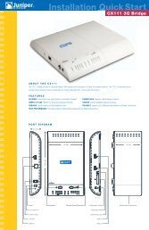
<strong>Interfaces</strong> <strong>for</strong> <strong>EX</strong> <strong>Series</strong> <strong>Switches</strong>Understanding Unicast RPF <strong>for</strong> <strong>EX</strong> <strong>Series</strong> <strong>Switches</strong>Unicast reverse-path <strong>for</strong>warding (RPF) helps protect the switch against denial-of-service(DoS) and distributed denial-of-service (DDoS) attacks by verifying the unicast sourceaddress of each packet that arrives on an ingress interface where unicast RPF is enabled.It also helps ensure that traffic arriving on ingress interfaces comes from a network sourcethat the receiving interface can reach.When you enable unicast RPF, the switch <strong>for</strong>wards a packet only if the receiving interfaceis the best return path to the packet's unicast source address. This is known as strictmode unicast RPF.NOTE: On <strong>Juniper</strong> <strong>Networks</strong> <strong>EX</strong>3200 and <strong>EX</strong>4200 Ethernet <strong>Switches</strong>, theswitch applies unicast RPF globally to all interfaces when unicast RPF isconfigured on any interface. For additional in<strong>for</strong>mation, see “Limitations ofthe Unicast RPF Implementation on <strong>EX</strong>3200 and <strong>EX</strong>4200 <strong>Switches</strong>” onpage 15.This topic covers:• Unicast RPF <strong>for</strong> <strong>EX</strong> <strong>Series</strong> <strong>Switches</strong> Overview on page 12• Unicast RPF Implementation <strong>for</strong> <strong>EX</strong> <strong>Series</strong> <strong>Switches</strong> on page 13• When to Enable Unicast RPF on page 13• When Not to Enable Unicast RPF on page 14• Limitations of the Unicast RPF Implementation on <strong>EX</strong>3200 and <strong>EX</strong>4200<strong>Switches</strong> on page 15Unicast RPF <strong>for</strong> <strong>EX</strong> <strong>Series</strong> <strong>Switches</strong> OverviewUnicast RPF functions as an ingress filter that reduces the <strong>for</strong>warding of IP packets thatmight be spoofing an address. By default, unicast RPF is disabled on the switch interfaces.The type of unicast RPF provided on the switches—that is, strict mode unicast RPF isespecially useful on untrusted interfaces. An untrusted interface is an interface whereuntrusted users or processes can place packets on the network segment.The switch supports only the active paths method of determining the best return pathback to a unicast source address. The active paths method looks up the best reversepath entry in the <strong>for</strong>warding table. It does not consider alternate routes specified usingrouting-protocol-specific methods when determining the best return path.If the <strong>for</strong>warding table lists the receiving interface as the interface to use to <strong>for</strong>ward thepacket back to its unicast source, it is the best return path interface. Strict mode unicastRPF recognizes only one best return path to a unicast source address.Use strict mode unicast RPF only on symmetrically routed interfaces. (For in<strong>for</strong>mationabout symmetrically routed interfaces, see “When to Enable Unicast RPF” on page 13.)12Copyright © 2012, <strong>Juniper</strong> <strong>Networks</strong>, Inc.
Chapter 1: <strong>Interfaces</strong> OverviewFor more in<strong>for</strong>mation about strict unicast RPF, see RFC 3704, Ingress Filtering <strong>for</strong>Multihomed <strong>Networks</strong> at http://www.ietf.org/rfc/rfc3704.txt.Unicast RPF Implementation <strong>for</strong> <strong>EX</strong> <strong>Series</strong> <strong>Switches</strong>This section includes:• Unicast RPF Packet Filtering on page 13• Bootstrap Protocol (BOOTP) and DHCP Requests on page 13• Default Route Handling on page 13Unicast RPF Packet FilteringWhen you enable unicast RPF on the switch, the switch handles traffic in the followingmanner:• If the switch receives a packet on the interface that is the best return path to the unicastsource address of that packet, the switch <strong>for</strong>wards the packet.• If the best return path from the switch to the packet's unicast source address is notthe receiving interface, the switch discards the packet.• If the switch receives a packet that has a source IP address that does not have a routingentry in the <strong>for</strong>warding table, the switch discards the packet.Bootstrap Protocol (BOOTP) and DHCP RequestsBootstrap protocol (BOOTP) and DHCP request packets are sent with a broadcast MACaddress and there<strong>for</strong>e the switch does not per<strong>for</strong>m unicast RPF checks on them. Theswitch <strong>for</strong>wards all BOOTP packets and DHCP request packets without per<strong>for</strong>mingunicast RPF checks.Default Route HandlingIf the best return path to the source is the default route (0.0.0.0) and the default routepoints to reject, the switch discards all unicast RPF packets. If the default route pointsto a valid network interface, the switch per<strong>for</strong>ms a normal unicast RPF check on thepackets.When to Enable Unicast RPFEnable unicast RPF when you want to ensure that traffic arriving on a network interfacecomes from a source that resides on a network that that interface can reach. You canenable unicast RPF on untrusted interfaces to filter spoofed packets. For example, acommon application <strong>for</strong> unicast RPF is to help defend an enterprise network fromDoS/DDoS attacks coming from the Internet.Enable unicast RPF only on symmetrically routed interfaces. A symmetrically routedinterface uses the same route in both directions between the source and the destination,as shown in Figure 1 on page 14. Symmetrical routing means that if an interface receivesa packet, the switch uses the same interface to send a reply to the packet source (thereceiving interface matches the <strong>for</strong>warding-table entry <strong>for</strong> the best return path to thesource).Copyright © 2012, <strong>Juniper</strong> <strong>Networks</strong>, Inc.13
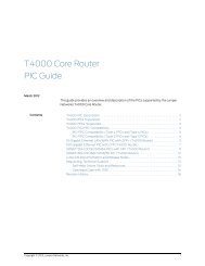
<strong>Interfaces</strong> <strong>for</strong> <strong>EX</strong> <strong>Series</strong> <strong>Switches</strong>Figure 1: Symmetrically Routed <strong>Interfaces</strong>Enabling unicast RPF on asymmetrically routed interfaces (where different interfacesreceive a packet and reply to its source) results in packets from legitimate sources beingfiltered (discarded) because the best return path is not the same interface that receivedthe packet.The following switch interfaces are most likely to be symmetrically routed and thus arecandidates <strong>for</strong> unicast RPF enabling:• The service provider edge to a customer• The customer edge to a service provider• A single access point out of the network (usually on the network perimeter)• A terminal network that has only one linkNOTE: Because unicast RPF is enabled globally on <strong>EX</strong>3200 and <strong>EX</strong>4200switches, ensure that all interfaces are symmetrically routed be<strong>for</strong>e youenable unicast RPF on those switches. Enabling unicast RPF onasymmetrically routed interfaces results in packets from legitimate sourcesbeing filtered.TIP: Enabling unicast RPF as close as possible to the traffic source stopsspoofed traffic be<strong>for</strong>e it can proliferate or reach interfaces that do not haveunicast RPF enabled.When Not to Enable Unicast RPFTypically, you will not enable unicast RPF if:• Switch interfaces are multihomed.• Switch interfaces are trusted interfaces.• BGP is carrying prefixes and some of those prefixes are not advertised or are notaccepted by the ISP under its policy. (The effect in this case is the same as filtering aninterface by using an incomplete access list.)• Switch interfaces face the network core. Core-facing interfaces are usuallyasymmetrically routed.An asymmetrically routed interface uses different paths to send and receive packetsbetween the source and the destination, as shown in Figure 2 on page 15. This means14Copyright © 2012, <strong>Juniper</strong> <strong>Networks</strong>, Inc.
Chapter 1: <strong>Interfaces</strong> Overviewthat if an interface receives a packet, that interface does not match the <strong>for</strong>warding tableentry as the best return path back to the source. If the receiving interface is not the bestreturn path to the source of a packet, unicast RPF causes the switch to discard the packeteven though it comes from a valid source.Figure 2: Asymmetrically Routed <strong>Interfaces</strong>NOTE: Do not enable unicast RPF on <strong>EX</strong>3200 and <strong>EX</strong>4200 switches if anyswitch interfaces are asymmetrically routed, because unicast RPF is enabledglobally on all interfaces of those switches. All switch interfaces must besymmetrically routed <strong>for</strong> you to enable unicast RPF without the risk of theswitch discarding traffic that you want to <strong>for</strong>ward.Limitations of the Unicast RPF Implementation on <strong>EX</strong>3200 and <strong>EX</strong>4200 <strong>Switches</strong>On <strong>EX</strong>3200 and <strong>EX</strong>4200 switches, the switch implements unicast RPF on a global basis.You cannot enable unicast RPF on a per-interface basis. Unicast RPF is globally disabledby default.• When you enable unicast RPF on any interface, it is automatically enabled on all switchinterfaces, including link aggregation groups (LAGs) and routed VLAN interfaces (RVIs).• When you disable unicast RPF on the interface (or interfaces) on which you enabledunicast RPF, it is automatically disabled on all switch interfaces.NOTE: You must explicitly disable unicast RPF on every interface on whichit was explicitly enabled or unicast RPF remains enabled on all switchinterfaces.The <strong>EX</strong>3200 and <strong>EX</strong>4200 switches do not per<strong>for</strong>m unicast RPF filtering on equal-costmultipath (ECMP) traffic. The unicast RPF check examines only one best return path tothe packet source, but ECMP traffic employs an address block consisting of multiplepaths.Using unicast RPF to filter ECMP traffic on <strong>EX</strong>3200 and <strong>EX</strong>4200 switches can result inthe switch discarding packets that you want to <strong>for</strong>ward because the unicast RPF filterdoes not examine the entire ECMP address block.RelatedDocumentation• Example: Configuring Unicast RPF on an <strong>EX</strong> <strong>Series</strong> Switch on page 49• Configuring Unicast RPF (CLI Procedure) on page 122Copyright © 2012, <strong>Juniper</strong> <strong>Networks</strong>, Inc.15
<strong>Interfaces</strong> <strong>for</strong> <strong>EX</strong> <strong>Series</strong> <strong>Switches</strong>• Disabling Unicast RPF (CLI Procedure) on page 123Understanding IP Directed Broadcast <strong>for</strong> <strong>EX</strong> <strong>Series</strong> <strong>Switches</strong>IP directed broadcast helps you implement remote administration tasks such as backupsand wake-on-LAN (WOL) application tasks by sending broadcast packets targeted atthe hosts in a specified destination subnet. IP directed broadcast packets traverse thenetwork in the same way as unicast IP packets until they reach the destination subnet.When they reach the destination subnet and IP directed broadcast is enabled on thereceiving switch, the switch translates (“explodes”) the IP directed broadcast packetinto a broadcast that floods the packet on the target subnet. All hosts on the targetsubnet receive the IP directed broadcast packet.This topic covers:• IP Directed Broadcast <strong>for</strong> <strong>EX</strong> <strong>Series</strong> <strong>Switches</strong> Overview on page 16• IP Directed Broadcast Implementation <strong>for</strong> <strong>EX</strong> <strong>Series</strong> <strong>Switches</strong> on page 16• When to Enable IP Directed Broadcast on page 17• When Not to Enable IP Directed Broadcast on page 17IP Directed Broadcast <strong>for</strong> <strong>EX</strong> <strong>Series</strong> <strong>Switches</strong> OverviewIP directed broadcast packets have a destination IP address that is a valid broadcastaddress <strong>for</strong> the subnet that is the target of the directed broadcast (the target subnet).The intent of an IP directed broadcast is to flood the target subnet with the broadcastpackets without broadcasting to the entire network. IP directed broadcast packets cannotoriginate from the target subnet.When you send an IP directed broadcast packet, as it travels to the target subnet, thenetwork <strong>for</strong>wards it in the same way as it <strong>for</strong>wards a unicast packet. When the packetreaches a switch that is directly connected to the target subnet, the switch checks to seewhether IP directed broadcast is enabled on the interface that is directly connected tothe target subnet:• If IP directed broadcast is enabled on that interface, the switch broadcasts the packeton that subnet by rewriting the destination IP address as the configured broadcast IPaddress <strong>for</strong> the subnet. The switch converts the packet to a link-layer broadcast packetthat every host on the network processes.• If IP directed broadcast is disabled on the interface that is directly connected to thetarget subnet, the switch drops the packet.IP Directed Broadcast Implementation <strong>for</strong> <strong>EX</strong> <strong>Series</strong> <strong>Switches</strong>You configure IP directed broadcast on a per-subnet basis by enabling IP directedbroadcast on the Layer 3 interface of the subnet’s VLAN. When the switch that isconnected to that subnet receives a packet that has the subnet’s broadcast IP addressas the destination address, the switch broadcasts the packet to all hosts on the subnet.16Copyright © 2012, <strong>Juniper</strong> <strong>Networks</strong>, Inc.
Chapter 1: <strong>Interfaces</strong> OverviewBy default, IP directed broadcast is disabled.When to Enable IP Directed BroadcastIP directed broadcast is disabled by default. Enable IP directed broadcast when you wantto per<strong>for</strong>m remote management or administration services such as backups or WOLtasks on hosts in a subnet that does not have a direct connection to the Internet.Enabling IP directed broadcast on a subnet affects only the hosts within that subnet.Only packets received on the subnet’s Layer 3 interface that have the subnet’s broadcastIP address as the destination address are flooded on the subnet.When Not to Enable IP Directed BroadcastTypically, you do not enable IP directed broadcast on subnets that have direct connectionsto the Internet. Disabling IP directed broadcast on a subnet’s Layer 3 interface affectsonly that subnet. If you disable IP directed broadcast on a subnet and a packet that hasthe broadcast IP address of that subnet arrives at the switch, the switch drops thebroadcast packet.If a subnet has a direct connection to the Internet, enabling IP directed broadcast on itincreases the network’s susceptibility to denial-of-service (DoS) attacks.For example, a malicious attacker can spoof a source IP address (use a source IP addressthat is not the actual source of the transmission to deceive a network into identifying theattacker as a legitimate source) and send IP directed broadcasts containing InternetControl Message Protocol (ICMP) echo (ping) packets. When the hosts on the networkwith IP directed broadcast enabled receive the ICMP echo packets, they all send repliesto the victim that has the spoofed source IP address. This creates a flood of ping repliesin a DoS attack that can overwhelm the spoofed source address; this is known as a“smurf” attack. Another common DoS attack on exposed networks with IP directedbroadcast enabled is a “fraggle” attack, which is similar to a smurf attack except thatthe malicious packet is a User Datagram Protocol (UDP) echo packet instead of an ICMPecho packet.RelatedDocumentation• Example: Configuring IP Directed Broadcast on an <strong>EX</strong> <strong>Series</strong> Switch on page 53• Configuring IP Directed Broadcast (CLI Procedure) on page 124Understanding Interface Ranges on <strong>EX</strong> <strong>Series</strong> <strong>Switches</strong>You can use the interface ranges to group interfaces of the same type that share acommon configuration profile. This helps reduce the time and ef<strong>for</strong>t in configuringinterfaces on <strong>Juniper</strong> <strong>Networks</strong> <strong>EX</strong> <strong>Series</strong> Ethernet switches. The configurations commonto all the interfaces can be included in the interface range definition.The interface range definition contains the name of the interface range defined, thenames of the individual member interfaces that do not fall in a series of interfaces, arange of interfaces defined in the member range, and the configuration statementscommon to all the interfaces. An interface range defined with member ranges andindividual members but without any common configurations, is also a valid definition.Copyright © 2012, <strong>Juniper</strong> <strong>Networks</strong>, Inc.17
<strong>Interfaces</strong> <strong>for</strong> <strong>EX</strong> <strong>Series</strong> <strong>Switches</strong>NOTE: The interface range definition is supported only <strong>for</strong> Gigabit, 10-Gigabit,and Fast Ethernet interfaces.The common configurations defined in the interface range will be overridden by the localconfiguration.The defined interface ranges can be used at places where the interface node is used inthe following configuration hierarchies:• ethernet-switching-options analyzer name input egress interface• ethernet-switching-options analyzer name input ingress interface• ethernet-switching-options analyzer output interface• ethernet-switching-options bpdu-block interface• ethernet-switching-options interfaces• ethernet-switching-options redundant-trunk-group group-name interface• ethernet-switching-options secure-access-port interface• ethernet-switching-options voip interface• poe interface• protocols dot1x authentication interface• protocols gvrp interface• protocols igmp interface• protocols igmp-snooping vlan vlan-name interface• protocols isis interface• protocols link-management peer lmp-control-channel interface• protocols link-management te-link name interface• protocols lldp interface• protocols lldp-med interface• protocols mpls interface• protocols mstp interface• protocols mstp msti-id interface• protocols mstp msti-id vlan vlan-id interface• protocols oam ethernet link-fault-management interface• protocols ospf area• protocols pim interface• protocols rip group group-name neighbor18Copyright © 2012, <strong>Juniper</strong> <strong>Networks</strong>, Inc.
Chapter 1: <strong>Interfaces</strong> Overview• protocols ripng group group-name neighbor• protocols router-advertisement interface• protocols router-discovery interface• protocols rsvp interface• protocols sflow interfaces• protocols stp interface• protocols vstp vlan vlan-id interface• vlans vlan-name interfaceRelatedDocumentation• Interface Ranges on page 96• <strong>EX</strong> <strong>Series</strong> <strong>Switches</strong> <strong>Interfaces</strong> Overview on page 3• Configuring Gigabit Ethernet <strong>Interfaces</strong> (CLI Procedure) on page 64• Configuring Aggregated Ethernet Links (CLI Procedure) on page 113• Configuring a Layer 3 Subinterface (CLI Procedure) on page 121• interface-range on page 197802.1Q VLANs OverviewFor Ethernet, Fast Ethernet, Tri-Rate Ethernet copper, Gigabit Ethernet, 10-GigabitEthernet, and aggregated Ethernet interfaces supporting VPLS, the Junos OS supportsa subset of the IEEE 802.1Q standard <strong>for</strong> channelizing an Ethernet interface into multiplelogical interfaces, allowing many hosts to be connected to the same Gigabit Ethernetswitch, but preventing them from being in the same routing or bridging domain.RelatedDocumentation• Configuring Dynamic 802.1Q VLANs• 802.1Q VLAN IDs and Ethernet Interface Types• Enabling VLAN Tagging• Binding VLAN IDs to Logical <strong>Interfaces</strong>• Configuring VLAN Encapsulation• Configuring Extended VLAN Encapsulation• Guidelines <strong>for</strong> Configuring VLAN ID List-Bundled Logical <strong>Interfaces</strong> That Connect CCCs• Configuring a Layer 2 VPN Routing Instance on a VLAN-Bundled Logical Interface• Configuring a VLAN-Bundled Logical Interface to Support a Layer 2 VPN RoutingInstance• Specifying the Interface Over Which VPN Traffic Travels to the CE Router• Specifying the Interface to Handle Traffic <strong>for</strong> a CCC• Configuring a Layer 2 Circuit on a VLAN-Bundled Logical InterfaceCopyright © 2012, <strong>Juniper</strong> <strong>Networks</strong>, Inc.19
<strong>Interfaces</strong> <strong>for</strong> <strong>EX</strong> <strong>Series</strong> <strong>Switches</strong>• Configuring a VLAN-Bundled Logical Interface to Support a Layer 2 VPN RoutingInstance• Specifying the Interface to Handle Traffic <strong>for</strong> a CCC Connected to the Layer 2 Circuit• Example: Configuring a Layer 2 VPN Routing Instance on a VLAN-Bundled LogicalInterface• Example: Configuring a Layer 2 Circuit on a VLAN-Bundled Logical Interface• Configuring a Logical Interface <strong>for</strong> Access Mode• Configuring a Logical Interface <strong>for</strong> Trunk Mode• Configuring the VLAN ID List <strong>for</strong> a Trunk Interface• Configuring a Trunk Interface on a Bridge Network• Junos OS Ethernet <strong>Interfaces</strong> Configuration GuideUnderstanding Generic Routing EncapsulationTunneling provides a private, secure path <strong>for</strong> transporting packets through an otherwisepublic network by encapsulating packets inside a transport protocol known as an IPencapsulation protocol. Generic routing encapsulation (GRE) is an IP encapsulationprotocol that is used to transport packets over a network. In<strong>for</strong>mation is sent from onenetwork to the other through a GRE tunnel.This topic describes:• Overview of GRE on page 20• GRE Tunneling on page 21• Configuration Limitations <strong>for</strong> GRE on <strong>EX</strong> <strong>Series</strong> <strong>Switches</strong> on page 23Overview of GREGRE encapsulates packets into IP packets and redirects them to an intermediate host,where they are de-encapsulated and routed to their final destination. Because the routeto the intermediate host appears to the inner datagrams as one hop, <strong>Juniper</strong> <strong>Networks</strong><strong>EX</strong> <strong>Series</strong> Ethernet switches can operate as if they have a virtual point-to-point connectionwith each other. GRE tunnels allow routing protocols like RIP and OSPF to <strong>for</strong>ward datapackets from one switch to another switch across the Internet. In addition, GRE tunnelscan encapsulate multicast data streams <strong>for</strong> transmission over the Internet.GRE is described in RFC 2784 (obsoletes earlier RFCs 1701 and 1702). The switches supportRFC 2784, but not completely. (For a list of limitations, see “Configuration Limitations<strong>for</strong> GRE on <strong>EX</strong> <strong>Series</strong> <strong>Switches</strong>” on page 23.)As a tunnel source router, the switch encapsulates a payload packet <strong>for</strong> transport throughthe tunnel to a destination network. The payload packet is first encapsulated in a GREpacket, and the resulting GRE packet is encapsulated in a delivery protocol. The switchper<strong>for</strong>ming the role of a tunnel remote router extracts the tunneled packet and <strong>for</strong>wardsthe packet to the destination network.20Copyright © 2012, <strong>Juniper</strong> <strong>Networks</strong>, Inc.
Chapter 1: <strong>Interfaces</strong> OverviewGRE TunnelingData is routed by the system to the GRE endpoint over routes established in the routetable. (These routes can be statically configured or dynamically learned by routingprotocols such as RIP or OSPF.) When a data packet is received by the GRE endpoint, itis de-encapsulated and routed again by means of the endpoint configuration to thedestination address of the tunnel. In this way, each data packet traveling over the GREtunnel gets routed through the system twice.Because GRE tunnels are stateless, the endpoint of the tunnel contains no in<strong>for</strong>mationabout the state or availability of the remote tunnel endpoint. There<strong>for</strong>e, the switchoperating as a tunnel source router cannot change the state of the GRE tunnel interfaceto down if the remote endpoint is unreachable.For details of GRE tunneling, see:• Encapsulation and De-Encapsulation on the Switch on page 21• Number of Source and Destination Tunnels Allowed on a Switch on page 21• Class of Service on GRE Tunnels on page 22• Firewall Filters on GRE Tunnels on page 22Encapsulation and De-Encapsulation on the SwitchEncapsulation—A switch operating as a tunnel source router encapsulates and <strong>for</strong>wardsGRE packets as follows:1. When a switch receives a data packet (payload) to be tunneled, it sends the packetto the tunnel interface.2. The tunnel interface encapsulates the data in a GRE packet.3. The system encapsulates the GRE packet in an IP packet.4. The IP packet is <strong>for</strong>warded based on its destination address and routing table.De-encapsulation—A switch operating as a tunnel remote router handles GRE packetsas follows:1. When the destination switch receives the IP packet from the tunnel interface, theswitch checks the destination address.2. The IP header is removed, and the packet is submitted to the GRE protocol.3. The GRE protocol strips off the GRE header and submits the payload packet <strong>for</strong><strong>for</strong>warding.Number of Source and Destination Tunnels Allowed on a SwitchDepending on your network, you can configure up to approximately 500 GRE tunnels tooperate between switches transmitting IPv4 or IPv6 payload packets over GRE. If apassenger protocol in addition to IPv4 and IPv6 is used, you can configure up toapproximately 333 GRE tunnels between the switches.Copyright © 2012, <strong>Juniper</strong> <strong>Networks</strong>, Inc.21
<strong>Interfaces</strong> <strong>for</strong> <strong>EX</strong> <strong>Series</strong> <strong>Switches</strong>A switch can have a maximum of 20 tunnel source IP addresses configured, and eachtunnel source IP can be configured with up to 20 destination IP addresses on a secondswitch. As a result, the two connected switches can have a maximum of 400 GRE tunnels.If the first switch is also connected to a third switch, the possible maximum number oftunnels can reach 500.Class of Service on GRE TunnelsWhen a network experiences congestion and delay, some packets might be dropped.Junos OS class of service (CoS) divides traffic into classes to which you can apply differentlevels of throughput and packet loss when congestion occurs and thereby set rules <strong>for</strong>packet loss. For CoS details, see Junos OS CoS <strong>for</strong> <strong>EX</strong> <strong>Series</strong> <strong>Switches</strong> Overview.The following CoS components are available on a switch operating as a GRE tunnelsource router or GRE tunnel remote router:• At the GRE tunnel source—On a switch operating as a tunnel source router, you canapply CoS classifiers on an ingress port or on a GRE port, with the following results onCoS component support on tunneled packets:• Schedulers only—Based on the CoS classification on the ingress port, you can applyCoS schedulers on a GRE port of the switch to define output queues and control thetransmission of packets through the tunnel after GRE encapsulation. However, youcannot apply CoS rewrite rules to these packets.• Schedulers and rewrite rules—Based on the CoS classification on the GRE port, youcan apply both schedulers and rewrite rules to the encapsulated packets transmittedthrough the tunnel.• At the GRE tunnel endpoint—When the switch is a tunnel remote router, you can applyCoS classifiers on the GRE port and schedulers and rewrite rules on the egress port tocontrol the transmission of a de-encapsulated GRE packet out the egress port.Firewall Filters on GRE TunnelsFirewall filters provide rules that define whether to permit, deny, or <strong>for</strong>ward packets thatare transiting an interface on a switch from a source address to a destination address.For details, see Firewall Filters <strong>for</strong> <strong>EX</strong> <strong>Series</strong> <strong>Switches</strong> Overview.The effectiveness of a firewall filter on a packet sent through a GRE tunnel depends onwhether a switch is at the source or endpoint of the tunnel:• GRE tunnel source—On a switch operating as a tunnel source router, you can configurea firewall filter on a egress port to control tunnel payload packets andGRE-encapsulated IP packets at the tunnel source.• GRE tunnel endpoint—When the switch is a tunnel remote router, a firewall filter cancontrol a GRE packet only after the packet has been de-encapsulated.22Copyright © 2012, <strong>Juniper</strong> <strong>Networks</strong>, Inc.
Chapter 1: <strong>Interfaces</strong> OverviewConfiguration Limitations <strong>for</strong> GRE on <strong>EX</strong> <strong>Series</strong> <strong>Switches</strong>Some GRE tunneling features are not currently available on <strong>EX</strong> <strong>Series</strong> switches. Be awareof the following limitations when you are configuring GRE on a switch:• Unsupported features—GRE on the switches does not support the following features:• Virtual routing over GRE• Bidirectional Forwarding Detection (BFD) protocol over GRE distributed mode• MPLS over GRE tunnels• GRE keepalives• GRE keys, payload packet fragmentation, and sequence numbers <strong>for</strong> fragmentedpackets• BGP dynamic tunnels• Plat<strong>for</strong>m limitation—Encapsulation over GRE tunnels is supported on <strong>EX</strong>3200, <strong>EX</strong>4200,and <strong>EX</strong>8200 switches. However, de-encapsulation is supported only on <strong>EX</strong>3200 and<strong>EX</strong>4200 switches.• IPv6 limitation—Both IPv4 and IPv6 packets are accepted as payload packets <strong>for</strong> GREencapsulation, but only IPv4 is supported as the GRE delivery protocol (the protocolthrough the tunnel).• OSPF limitation—Enabling OSPF on a GRE interface creates two equal-cost routes tothe destination: one through the Ethernet network or uplink interface (<strong>for</strong> example,ge-fpc/pic/port) and the other through the tunnel interface (gr-fpc/pic/port). If data isrouted through the tunnel interface, the interface might go down. To keep the interfaceoperational, we recommend that you use a static route, disable OSPF on the tunnelinterface, or configure the peer not to advertise the tunnel destination over the tunnelinterface.RelatedDocumentation• Configuring Generic Routing Encapsulation Tunneling (CLI Procedure) on page 128Copyright © 2012, <strong>Juniper</strong> <strong>Networks</strong>, Inc.23
<strong>Interfaces</strong> <strong>for</strong> <strong>EX</strong> <strong>Series</strong> <strong>Switches</strong>Understanding Multicast Load Balancing Over 10-Gigabit Links <strong>for</strong> Routed MulticastTraffic on <strong>Switches</strong>Streaming video technology was introduced in 1997 and multicast protocols weresubsequently developed to reduce data replication and network overloads. Withmulticasting, servers can send a single stream to a group of recipients instead of manyunicast streams. Multicasting plus streamed video boosted the evolution of streamingfrom an occasional company presentation to a constant stream of movies, real-timedata, news clips, and amateur videos flowing nonstop to computers, TVs, tablets andphones. All of these streams quickly overcame the capacity of network hardware, resultingin unacceptable blips and stutters in transmission.To satisfy the growing bandwidth demands, multiple links were virtually aggregated to<strong>for</strong>m bigger logical point-to-point link channels <strong>for</strong> the flow of data. These virtual linkcombinations are called multicast interfaces, also known as link aggregation groups(LAGs).Multicast load balancing manages the individual links in each LAG, making sure that eachlink is used efficiently. Hashing algorithms continually evaluate the data stream, adjustingstream distribution over the links in the LAG, so that no link is underutilized or overutilized.This topic includes:• Create LAGs <strong>for</strong> Multicasting in Increments of 10 Gigabits on page 24• When Should I Use Multicast Load Balancing? on page 25• How Does Multicast Load Balancing Work? on page 26• How Do I Implement Load Balancing on an <strong>EX</strong>8200 Switch? on page 27Create LAGs <strong>for</strong> Multicasting in Increments of 10 GigabitsThe maximum link size on <strong>Juniper</strong> <strong>Networks</strong> <strong>EX</strong>8200 Ethernet <strong>Switches</strong> is 10 gigabits.There<strong>for</strong>e, if you need a bigger link, you can combine up to four 10-gigabit links. In Figure3 on page 25, four 10-gigabit links have been aggregated to <strong>for</strong>m each 40-gigabit link.24Copyright © 2012, <strong>Juniper</strong> <strong>Networks</strong>, Inc.
Chapter 1: <strong>Interfaces</strong> OverviewFigure 3: 40-Gigabit LAGs on <strong>EX</strong>8200 <strong>Switches</strong>When Should I Use Multicast Load Balancing?Use a LAG with multicast load balancing when you need a downstream link greater than10 gigabits. This need frequently arises when you act as a service provider or when youmulticast video to a large audience.To use multicast load balancing, you need the following:• An <strong>EX</strong>8200 switch—The standalone switch is supported but the Virtual Chassis is not.• A Layer 3 routed multicast setup—For in<strong>for</strong>mation on configuring multicasting, seeJunos OS Routing Protocols Configuration Guide.Copyright © 2012, <strong>Juniper</strong> <strong>Networks</strong>, Inc.25
<strong>Interfaces</strong> <strong>for</strong> <strong>EX</strong> <strong>Series</strong> <strong>Switches</strong>• Aggregated 10-gigabit links in a LAG—<strong>for</strong> in<strong>for</strong>mation on configuring LAGs withmulticasting, see “Configuring Aggregated Ethernet Links with Multicast Load Balancingon <strong>EX</strong>8200 <strong>Switches</strong> (CLI Procedure)” on page 130.How Does Multicast Load Balancing Work?<strong>Juniper</strong> <strong>Networks</strong> Junos operating system (Junos OS) supports the Link AggregationControl Protocol (LACP), which is a subcomponent of IEEE 802.3ad. LACP providesadditional functionality <strong>for</strong> LAGs and is supported only on Layer 3 interfaces. When trafficcan use multiple member links, traffic that is part of the same stream must always beon the same link.Multicast load balancing uses one of seven available IP address hashing algorithms anda technique called queue shuffling (alternating between two queues) to distribute andbalance the data, directing streams over all available aggregated links. You can selectone of the seven algorithms when you configure multicast load balancing, or you can usethe default algorithm, crc-sgip, which uses a cyclic rededundancy check algorithm onthe multicast packets’ group IP. We recommend that you start with the CRC SGIP defaultand try other options if this algorithm does not provide suiutable results. Six algorithmsare based on the hashed value of IP addresses (IPV4 or IPV6) and will produce the sameresult each time they are used. Only the balanced mode option produces varied resultsdepending on the order in which streams are added. See Table 6 on page 26 <strong>for</strong> morein<strong>for</strong>mation.Table 6: Hashing Algorithms Used by Multicast Load BalancingHash ModeBased OnBest Usecrc-sgipCyclic redundancy checkof multicast packets’source and group IPaddressDefault—all high per<strong>for</strong>mance management of IP traffic on 10-Gigabit Ethernetnetwork. Predictable assignment to same link each time. This mode is complexbut yields a good distributed hash.crc-gipCyclic redundancy checkof multicast packets’group IP addressPredictable assignment to same link each time. Try this mode when CRC SGIPdoes not give satisfactory results and the group IP addresses vary.crc-sipCyclic redundancy checkof multicast packets’source IP addressPredictable assignment to same link each time. Try this mode when CRC SGIPdoes not give satisfactory results and the stream sources vary.simple-sgipXOR calculation ofmulticast packets’source and group IPaddressPredictable assignment to same link each time. This is a simple hashing methodthat might not yield as even a distribution as CRC SGIP yields. Try this modewhen CRC SGIP does not give satisfactory results.simple-gipXOR calculation ofmulticast packets’ groupIP addressPredictable assignment to same link each time. This is a simple hashing methodthat might not yield as even a distribution as CRC GIP yields. Try this whenCRC GIP does not give satisfactory results and the group IP addresses vary.simple-sipXOR calculation ofmulticast packets’source IP addressPredictable assignment to same link each time. This is a simple hashing methodthat might not yield as even a distribution as CRC SIP yields. Try this modewhen CRC SIP does not give satisfactory results and stream sources vary.26Copyright © 2012, <strong>Juniper</strong> <strong>Networks</strong>, Inc.
Chapter 1: <strong>Interfaces</strong> OverviewTable 6: Hashing Algorithms Used by Multicast Load Balancing (continued)Hash ModeBased OnBest UsebalancedRound-robin calculationmethod used to identifymulticast links withlowest streams assignedBest balance is achieved but you cannot predict which link will be consistentlyused because that depends on the order in which streams come online. Usewhen consistent assignment is not needed after every reboot.How Do I Implement Load Balancing on an <strong>EX</strong>8200 Switch?Follow these recommendations to get the best throughput <strong>for</strong> load balancing:• Allow 25 percent unused bandwidth in the aggregated link to accommodate anydynamic imbalances due to link changes caused by sharing multicast interfaces.• For downstream links, use the same size multicast interfaces whenever possible. Also<strong>for</strong> downstream aggregated links, throughput is optimized when members of theaggregated link belong to the same devices.• For upstream aggregated links, use a Layer 3 link whenever possible (as opposed to arouted VLAN interface (RVI) link). Also <strong>for</strong> upstream aggregated links, throughput isoptimized when the members of the aggregated link belong to different devices.RelatedDocumentation• Example: Configuring Multicast Load Balancing on <strong>EX</strong>8200 <strong>Switches</strong> on page 56• Configuring Aggregated Ethernet Links with Multicast Load Balancing on <strong>EX</strong>8200<strong>Switches</strong> (CLI Procedure) on page 130Understanding How Energy Efficient Ethernet Reduces Power Consumption on<strong>Interfaces</strong>Energy Efficient Ethernet (EEE), an Institute of Electrical and Electronics Engineers (IEEE)802.3az standard, reduces the power consumption of physical layer devices (PHYs)during periods of low link utilization. EEE saves energy by putting part of the transmissioncircuit into low power mode when the link is idle.An Ethernet link consumes power even when a ink is idle. EEE provides a method to utilizepower in such a way that Ethernet links use power only during data transmission. EEEspecifies a signaling protocol, Low Power Idle (LPI) <strong>for</strong> achieving the power saving duringthe idle time of Ethernet links. EEE allows PHYs to exchange LPI indications to signal thetransition to low power mode when there is no traffic. LPI indicates when a link can goidle and when the link needs to resume after a predefined delay without impacting datatransmission.The following copper PHYs are standardized by IEEE 802.3az:• 100BASE-T• 1000BASE-T• 10GBASE-TCopyright © 2012, <strong>Juniper</strong> <strong>Networks</strong>, Inc.27
<strong>Interfaces</strong> <strong>for</strong> <strong>EX</strong> <strong>Series</strong> <strong>Switches</strong>RelatedDocumentation• Configuring Energy Efficient Ethernet on <strong>Interfaces</strong> (CLI Procedure) on page 13128Copyright © 2012, <strong>Juniper</strong> <strong>Networks</strong>, Inc.
PART 2Configuration• Configuration Examples on page 31• Configuration Tasks on page 63• Configuration Statements on page 133Copyright © 2012, <strong>Juniper</strong> <strong>Networks</strong>, Inc.29
<strong>Interfaces</strong> <strong>for</strong> <strong>EX</strong> <strong>Series</strong> <strong>Switches</strong>30Copyright © 2012, <strong>Juniper</strong> <strong>Networks</strong>, Inc.
CHAPTER 2Configuration Examples• Example: Configuring Aggregated Ethernet High-Speed Uplinks Between an <strong>EX</strong>4200Virtual Chassis Access Switch and an <strong>EX</strong>4200 Virtual Chassis DistributionSwitch on page 31• Example: Configuring Aggregated Ethernet High-Speed Uplinks with LACP Betweenan <strong>EX</strong>4200 Virtual Chassis Access Switch and an <strong>EX</strong>4200 Virtual Chassis DistributionSwitch on page 37• Example: Configuring Layer 3 Subinterfaces <strong>for</strong> a Distribution Switch and an AccessSwitch on page 42• Example: Configuring Unicast RPF on an <strong>EX</strong> <strong>Series</strong> Switch on page 49• Example: Configuring IP Directed Broadcast on an <strong>EX</strong> <strong>Series</strong> Switch on page 53• Example: Configuring Aggregated Ethernet <strong>Interfaces</strong> With Multicast Load Balancingon <strong>EX</strong>8200 <strong>Switches</strong> on page 56Example: Configuring Aggregated Ethernet High-Speed Uplinks Between an <strong>EX</strong>4200Virtual Chassis Access Switch and an <strong>EX</strong>4200 Virtual Chassis Distribution Switch<strong>EX</strong> <strong>Series</strong> switches allow you to combine multiple Ethernet links into one logical interface<strong>for</strong> higher bandwidth and redundancy. The ports that are combined in this manner arereferred to as a link aggregation group (LAG) or bundle. The number of Ethernet linksyou can combine into a LAG depends on your <strong>EX</strong> <strong>Series</strong> switch model. See “UnderstandingAggregated Ethernet <strong>Interfaces</strong> and LACP” on page 8 <strong>for</strong> more in<strong>for</strong>mation.This example describes how to configure uplink LAGs to connect a Virtual Chassis accessswitch to a Virtual Chassis distribution switch:• Requirements on page 31• Overview and Topology on page 32• Configuration on page 34• Verification on page 36• Troubleshooting on page 37RequirementsThis example uses the following software and hardware components:Copyright © 2012, <strong>Juniper</strong> <strong>Networks</strong>, Inc.31
<strong>Interfaces</strong> <strong>for</strong> <strong>EX</strong> <strong>Series</strong> <strong>Switches</strong>• Junos OS Release 9.0 or later <strong>for</strong> <strong>EX</strong> <strong>Series</strong> switches• Two <strong>EX</strong>4200-48P switches• Two <strong>EX</strong>4200-24F switches• Four XFP uplink modulesBe<strong>for</strong>e you configure the LAGs, be sure you have:• Configured the Virtual Chassis switches. See Configuring an <strong>EX</strong>4200, <strong>EX</strong>4500, or<strong>EX</strong>4550 Virtual Chassis (CLI Procedure).• Configured the uplink ports on the switches as trunk ports. See “Configuring GigabitEthernet <strong>Interfaces</strong> (CLI Procedure)” on page 64.Overview and TopologyFor maximum speed and resiliency, you can combine uplinks between an access switchand a distribution switch into LAGs. Using LAGs can be particularly effective whenconnecting a multimember Virtual Chassis access switch to a multimember VirtualChassis distribution switch.The Virtual Chassis access switch in this example is composed of two member switches.Each member switch has an uplink module with two 10-Gigabit Ethernet ports. Theseports are configured as trunk ports, connecting the access switch with the distributionswitch.Configuring the uplinks as LAGs has the following advantages:• Link Aggregation Control Protocol (LACP) can optionally be configured <strong>for</strong> linknegotiation.• It doubles the speed of each uplink from 10 Gbps to 20 Gbps.• If one physical port is lost <strong>for</strong> any reason (a cable is unplugged or a switch port fails,or one member switch is unavailable), the logical port transparently continues tofunction over the remaining physical port.The topology used in this example consists of one Virtual Chassis access switch and oneVirtual Chassis distribution switch. The access switch is composed of two <strong>EX</strong>4200-48Pswitches (SWA-0 and SWA-1), interconnected to each other with their Virtual Chassisports (VCPs) as member switches of Host-A. The distribution switch is composed of two<strong>EX</strong>4200-24F switches (SWD-0 and SWD-1), interconnected with their VCPs as memberswitches of Host-D.Each member of the access switch has an uplink module installed. Each uplink modulehas two ports. The uplinks are configured to act as trunk ports, connecting the accessswitch with the distribution switch. One uplink port from SWA-0 and one uplink port fromSWA-1 are combined as LAG ae0 to SWD-0. This link is used <strong>for</strong> one VLAN. The remaininguplink ports from SWA-0 and from SWA-1 are combined as a second LAG connection(ae1) to SWD-1. LAG ae1 is used <strong>for</strong> another VLAN.32Copyright © 2012, <strong>Juniper</strong> <strong>Networks</strong>, Inc.
Chapter 2: Configuration ExamplesNOTE: If the remote end of the LAG link is a security device, LACP might notbe supported because security devices require a deterministic configuration.In this case, do not configure LACP. All links in the LAG are permanentlyoperational unless the switch detects a link failure within the Ethernet physicallayer or data link layers.Figure 4: Topology <strong>for</strong> LAGs Connecting an <strong>EX</strong>4200 Virtual Chassis AccessSwitch to an <strong>EX</strong>4200 Virtual Chassis Distribution SwitchTable 7 on page 33 details the topology used in this configuration example.Table 7: Components of the Topology <strong>for</strong> Connecting a Virtual Chassis Access Switch to aVirtual Chassis Distribution SwitchSwitchHostname andVCIDBase HardwareUplink ModuleMember IDTrunk PortSWA-0Host-A AccessswitchVCID 1<strong>EX</strong>4200-48PswitchOne XFP uplinkmodule0xe-0/1/0 to SWD-0xe-0/1/1 to SWD-1SWA-1Host-A AccessswitchVCID 1<strong>EX</strong>4200-48PswitchOne XFP uplinkmodule1xe-1/1/0 to SWD-0xe-1/1/1 to SWD-1Copyright © 2012, <strong>Juniper</strong> <strong>Networks</strong>, Inc.33
<strong>Interfaces</strong> <strong>for</strong> <strong>EX</strong> <strong>Series</strong> <strong>Switches</strong>Table 7: Components of the Topology <strong>for</strong> Connecting a Virtual Chassis Access Switch to aVirtual Chassis Distribution Switch (continued)SwitchHostname andVCIDBase HardwareUplink ModuleMember IDTrunk PortSWD-0Host-D DistributionswitchVCID 4<strong>EX</strong>4200 L-24FswitchOne XFP uplinkmodule0xe-0/1/0 to SWA-0xe-0/1/1 to SWA-1SWD-1Host-D DistributionswitchVCID 4<strong>EX</strong>4200 L-24FswitchOne XFP uplinkmodule1xe-1/1/0 to SWA-0xe-1/1/1 to SWA-1ConfigurationTo configure two uplink LAGs from the Virtual Chassis access switch to the Virtual Chassisdistribution switch:CLI QuickConfigurationTo quickly configure aggregated Ethernet high-speed uplinks between a Virtual Chassisaccess switch and a Virtual Chassis distribution switch, copy the following commandsand paste them into the switch terminal window:[edit]set chassis aggregated-devices ethernet device-count 2set interfaces ae0 aggregated-ether-options minimum-links 1set interfaces ae0 aggregated-ether-options link-speed 10gset interfaces ae1 aggregated-ether-options minimum-links 1set interfaces ae1 aggregated-ether-options link-speed 10gset interfaces ae0 unit 0 family inet address 192.0.2.0/25set interfaces ae1 unit 0 family inet address 192.0.2.128/25set interfaces xe-0/1/0 ether-options 802.3ad ae0set interfaces xe-1/1/0 ether-options 802.3ad ae0set interfaces xe-0/1/1 ether-options 802.3ad ae1set interfaces xe-1/1/1 ether-options 802.3ad ae1Step-by-StepProcedureTo configure aggregated Ethernet high-speed uplinks between a Virtual Chassis accessswitch and a Virtual Chassis distribution switch:1. Specify the number of LAGs to be created on the chassis:[edit chassis]user@Host-A# set aggregated-devices ethernet device-count 22. Specify the number of links that need to be present <strong>for</strong> the ae0 LAG interface to beup:[edit interfaces]user@Host-A# set ae0 aggregated-ether-options minimum-links 13. Specify the number of links that need to be present <strong>for</strong> the ae1 LAG interface to beup:[edit interfaces]user@Host-A# set ae1 aggregated-ether-options minimum-links 14. Specify the media speed of the ae0 link:[edit interfaces]user@Host-A# set ae0 aggregated-ether-options link-speed 10g34Copyright © 2012, <strong>Juniper</strong> <strong>Networks</strong>, Inc.
Chapter 2: Configuration Examples5. Specify the media speed of the ae1 link:[edit interfaces]user@Host-A# set ae1 aggregated-ether-options link-speed 10g6. Specify the interface ID of the uplinks to be included in LAG ae0:[edit interfaces]user@Host-A# set xe-0/1/0 ether-options 802.3ad ae0user@Host-A# set xe-1/1/0 ether-options 802.3ad ae07. Specify the interface ID of the uplinks to be included in LAG ae1:[edit interfaces]user@Host-A# set xe-0/1/1 ether-options 802.3ad ae1user@Host-A# set xe-1/1/1 ether-options 802.3ad ae18. Specify that LAG ae0 belongs to the subnet <strong>for</strong> the employee broadcast domain:[edit interfaces]user@Host-A# set ae0 unit 0 family inet address 192.0.2.0/259. Specify that LAG ae1 belongs to the subnet <strong>for</strong> the guest broadcast domain:[edit interfaces]user@Host-A# set ae1 unit 0 family inet address 192.0.2.128/25Display the results of the configuration:[edit]chassis {aggregated-devices {ethernet {device-count 2;}}}interfaces {ae0 {aggregated-ether-options {link-speed 10g;minimum-links 1;}unit 0 {family inet {address 192.0.2.0/25;}}}ae1 {aggregated-ether-options {link-speed 10g;minimum-links 1;}unit 0 {family inet {address 192.0.2.128/25;}}xe–0/1/0 {ether-options {802.3ad ae0;Copyright © 2012, <strong>Juniper</strong> <strong>Networks</strong>, Inc.35
<strong>Interfaces</strong> <strong>for</strong> <strong>EX</strong> <strong>Series</strong> <strong>Switches</strong>}}xe–1/1/0 {ether-options {802.3ad ae0;}}xe–0/1/1 {ether-options {802.3ad ae1;}}xe–1/1/1 {ether-options {802.3ad ae1;}}}VerificationTo verify that switching is operational and two LAGs have been created, per<strong>for</strong>m thesetasks:• Verifying That LAG ae0 Has Been Created on page 36• Verifying That LAG ae1 Has Been Created on page 36Verifying That LAG ae0 Has Been CreatedPurposeVerify that LAG ae0 has been created on the switch.Actionshow interfaces ae0 terseInterface Admin Link Proto Local Remoteae0 up upae0.0 up up inet 192.0.2.0/25MeaningThe output confirms that the ae0 link is up and shows the family and IP address assignedto this link.Verifying That LAG ae1 Has Been CreatedPurposeVerify that LAG ae1 has been created on the switchActionshow interfaces ae1 terseInterface Admin Link Proto Local Remoteae1 up downae1.0 up down inet 192.0.2.128/25MeaningThe output shows that the ae1 link is down.36Copyright © 2012, <strong>Juniper</strong> <strong>Networks</strong>, Inc.
Chapter 2: Configuration ExamplesTroubleshootingTroubleshooting a LAG That Is DownProblemThe show interfaces terse command shows that the LAG is down.SolutionCheck the following:• Verify that there is no configuration mismatch.• Verify that all member ports are up.• Verify that a LAG is part of family ethernet switching (Layer 2 LAG) or family inet (Layer3 LAG).• Verify that the LAG member is connected to the correct LAG at the other end.• Verify that the LAG members belong to the same switch (or the same Virtual Chassis).RelatedDocumentation• Example: Configuring an <strong>EX</strong>4200 Virtual Chassis with a Master and Backup in a SingleWiring Closet• Example: Configuring Aggregated Ethernet High-Speed Uplinks with LACP Betweenan <strong>EX</strong>4200 Virtual Chassis Access Switch and an <strong>EX</strong>4200 Virtual Chassis DistributionSwitch on page 37• Example: Connecting an Access Switch to a Distribution Switch.• Virtual Chassis Cabling Configuration Examples <strong>for</strong> <strong>EX</strong>4200 <strong>Switches</strong>• Installing an Uplink Module in an <strong>EX</strong>4200 Switch• Uplink Modules in <strong>EX</strong>4200 <strong>Switches</strong>Example: Configuring Aggregated Ethernet High-Speed Uplinks with LACP Betweenan <strong>EX</strong>4200 Virtual Chassis Access Switch and an <strong>EX</strong>4200 Virtual Chassis DistributionSwitch<strong>EX</strong> <strong>Series</strong> switches allow you to combine multiple Ethernet links into one logical interface<strong>for</strong> higher bandwidth and redundancy. The ports that are combined in this manner arereferred to as a link aggregation group (LAG) or bundle. <strong>EX</strong> <strong>Series</strong> switches allow you tofurther enhance these links by configuring Link Aggregation Control Protocol (LACP).This example describes how to overlay LACP on the LAG configurations that were createdin “Example: Configuring Aggregated Ethernet High-Speed Uplinks Between an <strong>EX</strong>4200Virtual Chassis Access Switch and an <strong>EX</strong>4200 Virtual Chassis Distribution Switch” onpage 31:• Requirements on page 38• Overview and Topology on page 38• Configuring LACP <strong>for</strong> the LAGs on the Virtual Chassis Access Switch on page 38• Configuring LACP <strong>for</strong> the LAGs on the Virtual Chassis Distribution Switch on page 39Copyright © 2012, <strong>Juniper</strong> <strong>Networks</strong>, Inc.37
<strong>Interfaces</strong> <strong>for</strong> <strong>EX</strong> <strong>Series</strong> <strong>Switches</strong>• Verification on page 40• Troubleshooting on page 41RequirementsThis example uses the following software and hardware components:• Junos OS Release 9.0 or later <strong>for</strong> <strong>EX</strong> <strong>Series</strong> switches• Two <strong>EX</strong>4200-48P switches• Two <strong>EX</strong>4200-24F switches• Four <strong>EX</strong> <strong>Series</strong> XFP uplink modulesBe<strong>for</strong>e you configure LACP, be sure you have:• Set up the Virtual Chassis switches. See Configuring an <strong>EX</strong>4200, <strong>EX</strong>4500, or <strong>EX</strong>4550Virtual Chassis (CLI Procedure).• Configured the uplink ports on the switches as trunk ports. See “Configuring GigabitEthernet <strong>Interfaces</strong> (CLI Procedure)” on page 64.• Configured the LAGs. See “Example: Configuring Aggregated Ethernet High-SpeedUplinks Between an <strong>EX</strong>4200 Virtual Chassis Access Switch and an <strong>EX</strong>4200 VirtualChassis Distribution Switch” on page 31.Overview and TopologyThis example assumes that you are familiar with “Example: Configuring AggregatedEthernet High-Speed Uplinks Between an <strong>EX</strong>4200 Virtual Chassis Access Switch andan <strong>EX</strong>4200 Virtual Chassis Distribution Switch” on page 31. The topology in this exampleis exactly the same as the topology in that other example. This example shows how touse LACP to enhance the LAG functionality.LACP exchanges are made between actors (the transmitting link) and partners (thereceiving link). The LACP mode can be either active or passive.NOTE: If the actor and partner are both in passive mode, they do not exchangeLACP packets, which results in the aggregated Ethernet links not coming up.By default, LACP is in passive mode. To initiate transmission of LACP packetsand responses to LACP packets, you must enable LACP in active mode.By default, the actor and partner send LACP packets every second.The interval can be fast (every second) or slow (every 30 seconds).Configuring LACP <strong>for</strong> the LAGs on the Virtual Chassis Access SwitchTo configure LACP <strong>for</strong> the access switch LAGs, per<strong>for</strong>m these tasks:CLI QuickConfigurationTo quickly configure LACP <strong>for</strong> the access switch LAGs, copy the following commandsand paste them into the switch terminal window:38Copyright © 2012, <strong>Juniper</strong> <strong>Networks</strong>, Inc.
Chapter 2: Configuration Examples[edit]set interfaces ae0 aggregated-ether-options lacp active periodic fastset interfaces ae1 aggregated-ether-options lacp active periodic fastStep-by-StepProcedureTo configure LACP <strong>for</strong> Host-A LAGs ae0 and ae1:1. Specify the aggregated Ethernet options <strong>for</strong> both bundles:[edit interfaces]user@Host-A#set ae0 aggregated-ether-options lacp active periodic fastuser@Host-A#set ae1 aggregated-ether-options lacp active periodic fastResultsDisplay the results of the configuration:[edit interfaces]user@Host-A# showae0 {aggregated-ether-options {lacp {active;periodic fast;}}}ae1 {aggregated-ether-options {lacp {active;periodic fast;}}}Configuring LACP <strong>for</strong> the LAGs on the Virtual Chassis Distribution SwitchTo configure LACP <strong>for</strong> the two uplink LAGs from the Virtual Chassis access switch to theVirtual Chassis distribution switch, per<strong>for</strong>m these tasks:CLI QuickConfigurationTo quickly configure LACP <strong>for</strong> the distribution switch LAGs, copy the following commandsand paste them into the switch terminal window:[edit interfaces]set ae0 aggregated-ether-options lacp passive periodic fastset ae1 aggregated-ether-options lacp passive periodic fastStep-by-StepProcedureTo configure LACP <strong>for</strong> Host D LAGs ae0 and ae1:1. Specify the aggregated Ethernet options <strong>for</strong> both bundles:[edit interfaces]user@Host-D#set ae0 aggregated-ether-options lacp passive periodic fastuser@Host-D#set ae1 aggregated-ether-options lacp passive periodic fastResultsDisplay the results of the configuration:[edit interfaces]user@Host-D# showae0 {Copyright © 2012, <strong>Juniper</strong> <strong>Networks</strong>, Inc.39
<strong>Interfaces</strong> <strong>for</strong> <strong>EX</strong> <strong>Series</strong> <strong>Switches</strong>aggregated-ether-options {lacp {passive;periodic fast;}}}ae1 {aggregated-ether-options {lacp {passiveperiodic fast;}}}VerificationTo verify that LACP packets are being exchanged, per<strong>for</strong>m these tasks:• Verifying the LACP Settings on page 40• Verifying That the LACP Packets Are Being Exchanged on page 40Verifying the LACP SettingsPurposeVerify that LACP has been set up correctly.ActionUse the show lacp interfaces interface-name command to check that LACP has beenenabled as active on one end.user@Host-A> show lacp interfaces xe-0/1/0Aggregated interface: ae0LACP state: Role Exp Def Dist Col Syn Aggr Timeout Activityxe-0/1/0 Actor No Yes No No No Yes Fast Activexe-0/1/0 Partner No Yes No No No Yes Fast PassiveLACP protocol: Receive State Transmit State Mux Statexe-0/1/0 Defaulted Fast periodic DetachedMeaningThe output indicates that LACP has been set up correctly and is active at one end.Verifying That the LACP Packets Are Being ExchangedPurposeVerify that LACP packets are being exchanged.ActionUse the show interfaces aex statistics command to display LACP in<strong>for</strong>mation.user@Host-A> show interfaces ae0 statistics40Copyright © 2012, <strong>Juniper</strong> <strong>Networks</strong>, Inc.
Chapter 2: Configuration ExamplesPhysical interface: ae0, Enabled, Physical link is DownInterface index: 153, SNMP ifIndex: 30Link-level type: Ethernet, MTU: 1514, Speed: Unspecified, Loopback: Disabled,Source filtering: Disabled, Flow control: Disabled, Minimum links needed: 1,Minimum bandwidth needed: 0Device flags : Present RunningInterface flags: Hardware-Down SNMP-Traps Internal: 0x0Current address: 02:19:e2:50:45:e0, Hardware address: 02:19:e2:50:45:e0Last flapped : NeverStatistics last cleared: NeverInput packets : 0Output packets: 0Input errors: 0, Output errors: 0Logical interface ae0.0 (Index 71) (SNMP ifIndex 34)Flags: Hardware-Down Device-Down SNMP-Traps Encapsulation: ENET2Statistics Packets pps Bytes bpsBundle:Input : 0 0 0 0Output: 0 0 0 0Protocol inetFlags: NoneAddresses, Flags: Dest-route-down Is-Preferred Is-PrimaryDestination: 10.10.10/24, Local: 10.10.10.1, Broadcast: 10.10.10.255MeaningThe output here shows that the link is down and that no protocol data units (PDUs) arebeing exchanged.TroubleshootingTo troubleshoot a nonworking LACP link, per<strong>for</strong>m these tasks:• Troubleshooting a Nonworking LACP Link on page 41Troubleshooting a Nonworking LACP LinkProblemThe LACP link is not working.SolutionCheck the following:• Remove the LACP configuration and verify whether the static LAG is up.• Verify that LACP is configured at both ends.• Verify that LACP is not passive at both ends.• Verify whether LACP protocol data units (PDUs) are being exchanged by running themonitor traffic-interface lag-member detail command.RelatedDocumentation• Example: Connecting an Access Switch to a Distribution Switch• Virtual Chassis Cabling Configuration Examples <strong>for</strong> <strong>EX</strong>4200 <strong>Switches</strong>• Installing an Uplink Module in an <strong>EX</strong>4200 Switch• Understanding Aggregated Ethernet <strong>Interfaces</strong> and LACP on page 8Copyright © 2012, <strong>Juniper</strong> <strong>Networks</strong>, Inc.41
<strong>Interfaces</strong> <strong>for</strong> <strong>EX</strong> <strong>Series</strong> <strong>Switches</strong>Example: Configuring Layer 3 Subinterfaces <strong>for</strong> a Distribution Switch and an AccessSwitchIn a large LAN, you commonly need to partition the network into multiple VLANs. Youcan configure Layer 3 subinterfaces to route traffic between the VLANs. In one commontopology, known as a “router on a stick” or a “one-armed router,” you connect a routerto an access switch with connections to multiple VLANs.This example describes how to create Layer 3 subinterfaces on trunk interfaces of adistribution switch and access switch so that you can route traffic among multiple VLANs:• Requirements on page 42• Overview and Topology on page 42• Configuring the Access Switch Subinterfaces on page 43• Configuring the Distribution Switch Subinterfaces on page 45• Verification on page 46RequirementsThis example uses the following hardware and software components:• For the distribution switch, one <strong>EX</strong>4200-24F switch. This model is designed to be usedas a distribution switch <strong>for</strong> aggregation or collapsed core network topologies and inspace-constrained data centers. It has twenty-four 1-Gigabit Ethernet fiber SFP portsand an <strong>EX</strong>-UM-2XFP uplink module with two 10-Gigabit Ethernet XFP ports.• For the access switch, any Layer 2 switch that supports 802.1Q VLAN tags.• Junos OS Release 9.2 or later <strong>for</strong> <strong>EX</strong> <strong>Series</strong> switches.Be<strong>for</strong>e you connect the switches, make sure you have:• Connected the two switches.• Configured the necessary VLANs. See Configuring VLANs <strong>for</strong> <strong>EX</strong> <strong>Series</strong> <strong>Switches</strong> (CLIProcedure) or Configuring VLANs <strong>for</strong> <strong>EX</strong> <strong>Series</strong> <strong>Switches</strong> (J-Web Procedure).Overview and TopologyIn a large office with multiple buildings and VLANs, you commonly aggregate traffic froma number of access switches into a distribution switch. This configuration example showsa simple topology to illustrate how to connect a single Layer 2 access switch connectedto multiple VLANs to a distribution switch, enabling traffic to pass between those VLANs.In the example topology, the LAN is segmented into five VLANs, all associated withinterfaces on the access switch. One 1-Gigabit Ethernet port on the access switch's uplinkmodule connects to one 1-Gigabit Ethernet port on the distribution switch.Table 8 on page 43 lists the settings <strong>for</strong> the example topology.42Copyright © 2012, <strong>Juniper</strong> <strong>Networks</strong>, Inc.
Chapter 2: Configuration ExamplesTable 8: Components of the Topology <strong>for</strong> Creating Layer 3 Subinterfaces on an Access Switchand a Distribution SwitchPropertyAccess switch hardwareSettingsAny Layer 2 switch with multiple 1-Gigabit Ethernet ports and at least one 1-GigabitEthernet uplink moduleDistribution switch hardware<strong>EX</strong>4200-24F, 24 1-Gigabit Ethernet fiber SPF ports (ge-0/0/0 through ge-0/0/23); one2-port 10-Gigabit Ethernet XFP uplink module (<strong>EX</strong>-UM-4SFP)VLAN names and tag IDsvlan1, tag 101vlan2, tag 102vlan3, tag 103vlan4, tag 104vlan5, tag 105VLAN subnetsvlan1: 1.1.1.0/24 (addresses 1.1.1.1 through 1.1.1.254)vlan2: 2.1.1.0/24 (addresses 2.1.1.1 through 2.1.1.254)vlan3: 3.1.1.0/24 (addresses 3.1.1.1 through 3.1.1.254)vlan4: 4.1.1.0/24 (addresses 4.1.1.1 through 4.1.1.254)vlan5: 5.1.1.0/24 (addresses 5.1.1.1 through 5.1.1.254)Port interfacesOn the access switch: ge-0/1/0On the distribution switch: ge-0/0/0Configuring the Access Switch SubinterfacesCLI QuickConfigurationTo quickly create and configure subinterfaces on the access switch, copy the followingcommands and paste them into the switch terminal window:[edit]set interfaces ge-0/1/0 vlan-taggingset interfaces ge-0/1/0 unit 0 vlan-id 101 family inet address 1.1.1.1/24set interfaces ge-0/1/0 unit 1 vlan-id 102 family inet address 2.1.1.1/24set interfaces ge-0/1/0 unit 2 vlan-id 103 family inet address 3.1.1.1/24set interfaces ge-0/1/0 unit 3 vlan-id 104 family inet address 4.1.1.1/24set interfaces ge-0/1/0 unit 4 vlan-id 105 family inet address 5.1.1.1/24Step-by-StepProcedureTo configure the subinterfaces on the access switch:1. On the trunk interface of the access switch, enable VLAN tagging:[edit interfaces ge-0/1/0]user@access-switch# set vlan-tagging2. Bind vlan1's VLAN ID to the logical interface:[edit interfaces ge-0/1/0]user@access-switch# set unit 0 vlan-id 1013. Set vlan1's subinterface IP address:Copyright © 2012, <strong>Juniper</strong> <strong>Networks</strong>, Inc.43
<strong>Interfaces</strong> <strong>for</strong> <strong>EX</strong> <strong>Series</strong> <strong>Switches</strong>[edit interfaces ge-0/1/0]user@access-switch# set unit 0 family inet address 1.1.1.1/244. Bind vlan2's VLAN ID to the logical interface:[edit interfaces ge-0/1/0]user@access-switch# set unit 1 vlan-id 1025. Set vlan2's subinterface IP address:[edit interfaces ge-0/1/0]user@access-switch# set unit 1 family inet address 2.1.1.1/246. Bind vlan3's VLAN ID to the logical interface:[edit interfaces ge-0/1/0]user@access-switch# set unit 2 vlan–id 1037. Set vlan3's subinterface IP address:[edit interfaces ge-0/1/0]user@access-switch# set unit 2 family inet address 3.1.1.1/248. Bind vlan4's VLAN ID to the logical interface:[edit interfaces ge-0/1/0]user@access-switch# set unit 3 vlan-id 1049. Set vlan4's subinterface IP address:[edit interfaces ge-0/1/0]user@access-switch# set unit 3 family inet address 4.1.1.1/2410. Bind vlan5's VLAN ID to the logical interface:[edit interfaces ge-0/1/0]user@access-switch# set unit 4 vlan-id 10511. Set vlan5's subinterface IP address:[edit interfaces ge-0/1/0]user@access-switch# set unit 4 family inet address 5.1.1.1/24Check the results of the configuration:user@access-switch> show configurationinterfaces {ge-0/1/0 {vlan-tagging;unit 0 {vlan-id 101;family inet {address 1.1.1.1/24;}}unit 1 {vlan-id 102;family inet {address 2.1.1.1/24;}}unit 2 {vlan-id 103;family inet {address 3.1.1.1/24;}}unit 3 {44Copyright © 2012, <strong>Juniper</strong> <strong>Networks</strong>, Inc.
Chapter 2: Configuration Examplesvlan-id 104;family inet {address 4.1.1.1/24;}}unit 4 {vlan-id 105;family inet {address 5.1.1.1/24;}}}Configuring the Distribution Switch SubinterfacesCLI QuickConfigurationTo quickly create and configure subinterfaces on the distribution switch, copy the followingcommands and paste them into the switch terminal window:[edit]set interfaces ge-0/0/0 vlan-taggingset interfaces ge-0/0/0 unit 0 vlan-id 101 family inet address 1.1.1.2/24set interfaces ge-0/0/0 unit 1 vlan-id 102 family inet address 2.1.1.2/24set interfaces ge-0/0/0 unit 2 vlan-id 103 family inet address 3.1.1.2/24set interfaces ge-0/0/0 unit 3 vlan-id 104 family inet address 4.1.1.2/24set interfaces ge-0/0/0 unit 4 vlan-id 105 family inet address 5.1.1.2/24Step-by-StepProcedureTo configure subinterfaces on the distribution switch:1. On the trunk interface of the distribution switch, enable VLAN tagging:[edit interfaces ge-0/0/0]user@distribution-switch# set vlan-tagging2. Bind vlan1's VLAN ID to the logical interface:[edit interfaces ge-0/0/0]user@distribution-switch# set unit 0 vlan-id 1013. Set vlan1's subinterface IP address:[edit interfaces ge-0/0/0]user@distribution-switch# set unit 0 family inet address 1.1.1.2/244. Bind vlan2's VLAN ID to the logical interface:[edit interfaces ge-0/0/0]user@distribution-switch# set unit 1 vlan-id 1025. Set vlan2's subinterface IP address:[edit interfaces ge-0/0/0]user@distribution-switch# set unit 1 family inet address 2.1.1.2/246. Bind vlan3's VLAN ID to the logical interface:[edit interfaces ge-0/0/0]user@distribution-switch# set unit 2 vlan-id 1037. Set vlan3's subinterface IP address:[edit interfaces ge-0/0/0]user@distribution-switch# set unit 2 family inet address 3.1.1.2/248. Bind vlan4's VLAN ID to the logical interface:[edit interfaces ge-0/0/0]user@distribution-switch# set unit 3 vlan-id 104Copyright © 2012, <strong>Juniper</strong> <strong>Networks</strong>, Inc.45
<strong>Interfaces</strong> <strong>for</strong> <strong>EX</strong> <strong>Series</strong> <strong>Switches</strong>9. Set vlan4's subinterface IP address:[edit interfaces ge-0/0/0]user@distribution-switch# set unit 3 family inet address 4.1.1.2/2410. Bind vlan5's VLAN ID to the logical interface:[edit interfaces ge-0/0/0]user@distribution-switch# set unit 4 vlan-id 10511. Set vlan5's subinterface IP address:[edit interfaces ge-0/0/0]user@distribution-switch# set unit 4 family inet address 5.1.1.2/24user@distribution-switch> show configurationinterfaces {ge-0/0/0 {vlan-tagging;unit 0 {vlan-id 101;family inet {address 1.1.1.2/24;}}unit 1 {vlan-id 102;family inet {address 2.1.1.2/24;}}unit 2 {vlan-id 103;family inet {address 3.1.1.2/24;}}unit 3 {vlan-id 104;family inet {address 4.1.1.2/24;}}unit 4 {vlan-id 105;family inet {address 5.1.1.2/24;}}}VerificationTo confirm that the configuration is working properly, per<strong>for</strong>m these tasks:• Verifying That Subinterfaces Were Created on page 47• Verifying That Traffic Passes Between VLANs on page 4746Copyright © 2012, <strong>Juniper</strong> <strong>Networks</strong>, Inc.
Chapter 2: Configuration ExamplesVerifying That Subinterfaces Were CreatedPurposeVerify that the subinterfaces were properly created on the access switch and distributionswitch.Action1.Use the show interfaces command on the access switch:user@access-switch> show interfaces ge-0/1/0 terseInterface Admin Link Proto Local Remotege-0/1/0 up upge-0/1/0.0 up up inet 1.1.1.1/24ge-0/1/0.1 up up inet 2.1.1.1/24ge-0/1/0.2 up up inet 3.1.1.1/24ge-0/1/0.3 up up inet 4.1.1.1/24ge-0/1/0.4 up up inet 5.1.1.1/24ge-0/1/0.32767 up up2. Use the show interfaces command on the distribution switch:user@distribution-switch> show interfaces ge-0/0/0 terseInterface Admin Link Proto Local Remotege-0/0/0 up upge-0/0/0.0 up up inet 1.1.1.2/24ge-0/0/0.1 up up inet 2.1.1.2/24ge-0/0/0.2 up up inet 3.1.1.2/24ge-0/0/0.3 up up inet 4.1.1.2/24ge-0/0/0.4 up up inet 5.1.1.2/24ge-0/0/0.32767 up upMeaningEach subinterface created is displayed as a ge-fpc/pic/port.x logical interface, where xis the unit number in the configuration. The status is listed as up, indicating the link isworking.Verifying That Traffic Passes Between VLANsPurposeVerify that the distribution switch is correctly routing traffic from one VLAN to another.ActionPing from the access switch to the distribution switch on each subinterface.1. From the access switch, ping the address of the vlan1 subinterface on the distributionswitch:user@access-switch> ping 1.1.1.2 count 4PING 1.1.1.2 (1.1.1.2): 56 data bytes64 bytes from 1.1.1.2: icmp_seq=0 ttl=64 time=0.333 ms64 bytes from 1.1.1.2: icmp_seq=1 ttl=64 time=0.113 ms64 bytes from 1.1.1.2: icmp_seq=2 ttl=64 time=0.112 ms64 bytes from 1.1.1.2: icmp_seq=3 ttl=64 time=0.158 ms--- 1.1.1.2 ping statistics ---4 packets transmitted, 4 packets received, 0% packet lossround-trip min/avg/max/stddev = 0.112/0.179/0.333/0.091 ms2. From the access switch, ping the address of the vlan2 subinterface on the distributionswitch:user@access-switch> ping 2.1.1.2 count 4Copyright © 2012, <strong>Juniper</strong> <strong>Networks</strong>, Inc.47
<strong>Interfaces</strong> <strong>for</strong> <strong>EX</strong> <strong>Series</strong> <strong>Switches</strong>PING 2.1.1.2 (2.1.1.2): 56 data bytes64 bytes from 2.1.1.2: icmp_seq=0 ttl=64 time=0.241 ms64 bytes from 2.1.1.2: icmp_seq=1 ttl=64 time=0.113 ms64 bytes from 2.1.1.2: icmp_seq=2 ttl=64 time=0.162 ms64 bytes from 2.1.1.2: icmp_seq=3 ttl=64 time=0.167 ms--- 2.1.1.2 ping statistics ---4 packets transmitted, 4 packets received, 0% packet lossround-trip min/avg/max/stddev = 0.113/0.171/0.241/0.046 ms3. From the access switch, ping the address of the vlan3 subinterface on the distributionswitch:user@access-switch> ping 3.1.1.2 count 4PING 3.1.1.2 (3.1.1.2): 56 data bytes64 bytes from 3.1.1.2: icmp_seq=0 ttl=64 time=0.341 ms64 bytes from 3.1.1.2: icmp_seq=1 ttl=64 time=0.162 ms64 bytes from 3.1.1.2: icmp_seq=2 ttl=64 time=0.112 ms64 bytes from 3.1.1.2: icmp_seq=3 ttl=64 time=0.208 ms--- 3.1.1.2 ping statistics ---4 packets transmitted, 4 packets received, 0% packet lossround-trip min/avg/max/stddev = 0.112/0.206/0.341/0.085 ms4. From the access switch, ping the address of the vlan4 subinterface on the distributionswitch:user@access-switch> ping 4.1.1.2 count 4PING 4.1.1.2 (4.1.1.2): 56 data bytes64 bytes from 4.1.1.2: icmp_seq=0 ttl=64 time=0.226 ms64 bytes from 4.1.1.2: icmp_seq=1 ttl=64 time=0.166 ms64 bytes from 4.1.1.2: icmp_seq=2 ttl=64 time=0.107 ms64 bytes from 4.1.1.2: icmp_seq=3 ttl=64 time=0.221 ms--- 4.1.1.2 ping statistics ---4 packets transmitted, 4 packets received, 0% packet lossround-trip min/avg/max/stddev = 0.107/0.180/0.226/0.048 ms5. From the access switch, ping the address of the vlan5 subinterface on the distributionswitch:user@access-switch> ping 5.1.1.2 count 4PING 5.1.1.2 (5.1.1.2): 56 data bytes64 bytes from 5.1.1.2: icmp_seq=0 ttl=64 time=0.224 ms64 bytes from 5.1.1.2: icmp_seq=1 ttl=64 time=0.104 ms64 bytes from 5.1.1.2: icmp_seq=2 ttl=64 time=0.102 ms64 bytes from 5.1.1.2: icmp_seq=3 ttl=64 time=0.170 ms--- 5.1.1.2 ping statistics ---4 packets transmitted, 4 packets received, 0% packet lossround-trip min/avg/max/stddev = 0.102/0.150/0.224/0.051 msMeaningIf all the ping packets are transmitted and are received by the destination address, thesubinterfaces are up and working.RelatedDocumentation• Understanding Layer 3 Logical <strong>Interfaces</strong>• Example: Connecting an Access Switch to a Distribution Switch• Configuring a Layer 3 Logical Interface48Copyright © 2012, <strong>Juniper</strong> <strong>Networks</strong>, Inc.
Chapter 2: Configuration Examples• Configuring a Layer 3 Subinterface (CLI Procedure) on page 121Example: Configuring Unicast RPF on an <strong>EX</strong> <strong>Series</strong> SwitchUnicast reverse-path <strong>for</strong>warding (RPF) helps protect the switch against denial-of-service(DoS) and distributed denial-of-service (DDoS) attacks by verifying the unicast sourceaddress of each packet that arrives on an ingress interface where unicast RPF is enabled.This example shows how to help defend the switch ingress interfaces againstdenial-of-service (DoS) and distributed denial-of-service (DDoS) attacks by configuringunicast reverse-path <strong>for</strong>warding (RPF) on a customer-edge interface to filter incomingtraffic:• Requirements on page 49• Overview and Topology on page 49• Configuration on page 50• Verification on page 50RequirementsThis example uses the following software and hardware components:• Junos OS Release 10.1 or later <strong>for</strong> <strong>EX</strong> <strong>Series</strong> switches• Two <strong>EX</strong>8200 switchesBe<strong>for</strong>e you begin, be sure you have:• Connected the two switches by symmetrically routed interfaces.• Ensured that the interface on which you will configure unicast RPF is symmetricallyrouted.Overview and TopologyLarge amounts of unauthorized traffic such as attempts to flood a network with fake(bogus) service requests in a denial-of-service (DoS) attack can consume networkresources and deny service to legitimate users. One way to help prevent DoS anddistributed denial-of-service (DDoS) attacks is to verify that incoming traffic originatesfrom legitimate network sources.Unicast RPF helps ensure that a traffic source is legitimate (authorized) by comparingthe source address of each packet that arrives on an interface to the <strong>for</strong>warding-tableentry <strong>for</strong> its source address. If the switch uses the same interface that the packet arrivedon to reply to the packet's source, this verifies that the packet originated from anauthorized source, and the switch <strong>for</strong>wards the packet. If the switch does not use thesame interface that the packet arrived on to reply to the packet's source, the packetmight have originated from an unauthorized source, and the switch discards the packet.Copyright © 2012, <strong>Juniper</strong> <strong>Networks</strong>, Inc.49
<strong>Interfaces</strong> <strong>for</strong> <strong>EX</strong> <strong>Series</strong> <strong>Switches</strong>This example uses two <strong>EX</strong>8200 switches. On <strong>EX</strong>3200 and <strong>EX</strong>4200 switches, you cannotconfigure individual interfaces <strong>for</strong> unicast RPF. On <strong>EX</strong>3200 and <strong>EX</strong>4200 switches, theswitch applies unicast RPF globally to all interfaces on the switch. See “UnderstandingUnicast RPF <strong>for</strong> <strong>EX</strong> <strong>Series</strong> <strong>Switches</strong>” on page 12 <strong>for</strong> more in<strong>for</strong>mation on limitationsregarding the configuration of unicast RPF on <strong>EX</strong>3200 and <strong>EX</strong>4200 switches.In this example, an enterprise network's system administrator wants to protect SwitchA against potential DoS and DDoS attacks from the Internet. The administrator configuresunicast RPF on interface ge-1/0/10 on Switch A. Packets arriving on interface ge-1/0/10on Switch A from the Switch B source also use incoming interface ge-1/0/10 as the bestreturn path to send packets back to the source.The topology of this configuration example uses two <strong>EX</strong>8200 switches, Switch A andSwitch B, connected by symmetrically routed interfaces:• Switch A is on the edge of an enterprise network. The interface ge-1/0/10 on Switch Aconnects to the interface ge-1/0/5 on Switch B.• Switch B is on the edge of the service provider network that connects the enterprisenetwork to the Internet.ConfigurationTo enable unicast RPF, per<strong>for</strong>m these tasks:CLI QuickConfigurationTo quickly configure unicast RPF on Switch A, copy the following command and pasteit into the switch terminal window:[edit interfaces]set ge-1/0/10 unit 0 family inet rpf-checkStep-by-StepProcedureTo configure unicast RPF on Switch A:1. Enable unicast RPF on interface ge-1/0/10:[edit interfaces]user@switch# set ge-1/0/10 unit 0 family inet rpf-checkResultsCheck the results:[edit interfaces]user@switch# showge-1/0/10 {unit 0 {family inet {rpf-check;}}}VerificationTo confirm that the configuration is correct, per<strong>for</strong>m these tasks:• Verifying That Unicast RPF Is Enabled on the Switch on page 5150Copyright © 2012, <strong>Juniper</strong> <strong>Networks</strong>, Inc.
Chapter 2: Configuration ExamplesVerifying That Unicast RPF Is Enabled on the SwitchPurposeVerify that unicast RPF is enabled.ActionVerify that unicast RPF is enabled on interface ge-1/0/10 by using the show interfacesge-1/0/10 extensive or show interfaces ge-1/0/10 detail command.user@switch> show interfaces ge-1/0/10 extensivePhysical interface: ge-1/0/10, Enabled, Physical link is DownInterface index: 139, SNMP ifIndex: 58, Generation: 140Link-level type: Ethernet, MTU: 1514, Speed: Auto, MAC-REWRITE Error: None,Loopback: Disabled, Source filtering: Disabled, Flow control: Enabled,Auto-negotiation: Enabled, Remote fault: OnlineDevice flags : Present RunningInterface flags: Hardware-Down SNMP-Traps Internal: 0x0Link flags : NoneCoS queues : 8 supported, 8 maximum usable queuesHold-times : Up 0 ms, Down 0 msCurrent address: 00:19:e2:50:95:ab, Hardware address: 00:19:e2:50:95:abLast flapped : NeverStatistics last cleared: NeverTraffic statistics:Input bytes : 0 0 bpsOutput bytes : 0 0 bpsInput packets: 0 0 ppsOutput packets: 0 0 ppsIPv6 transit statistics:Input bytes : 0Output bytes : 0Input packets: 0Output packets: 0Input errors:Errors: 0, Drops: 0, Framing errors: 0, Runts: 0, Policed discards: 0,L3 incompletes: 0, L2 channel errors: 0, L2 mismatch timeouts: 0,FIFO errors: 0, Resource errors: 0Output errors:Carrier transitions: 0, Errors: 0, Drops: 0, Collisions: 0, Aged packets: 0,FIFO errors: 0, HS link CRC errors: 0, MTU errors: 0, Resource errors: 0Egress queues: 8 supported, 4 in useQueue counters: Queued packets Transmitted packets Dropped packets0 best-ef<strong>for</strong>t 0 0 01 assured-<strong>for</strong>w 0 0 05 expedited-fo 0 0 07 network-cont 0 0 0Active alarms : LINKActive defects : LINKMAC statistics: Receive TransmitTotal octets 0 0Total packets 0 0Unicast packets 0 0Broadcast packets 0 0Multicast packets 0 0CRC/Align errors 0 0Copyright © 2012, <strong>Juniper</strong> <strong>Networks</strong>, Inc.51
<strong>Interfaces</strong> <strong>for</strong> <strong>EX</strong> <strong>Series</strong> <strong>Switches</strong>FIFO errors 0 0MAC control frames 0 0MAC pause frames 0 0Oversized frames 0Jabber frames 0Fragment frames 0VLAN tagged frames 0Code violations 0Filter statistics:Input packet count 0Input packet rejects 0Input DA rejects 0Input SA rejects 0Output packet count 0Output packet pad count 0Output packet error count 0CAM destination filters: 0, CAM source filters: 0Autonegotiation in<strong>for</strong>mation:Negotiation status: IncompletePacket Forwarding Engine configuration:Destination slot: 1Logical interface ge-1/0/10.0 (Index 69) (SNMP ifIndex 59) (Generation 135)Flags: Device-Down SNMP-Traps 0x0 Encapsulation: ENET2Traffic statistics:Input bytes : 0Output bytes : 0Input packets: 0Output packets: 0IPv6 transit statistics:Input bytes : 0Output bytes : 0Input packets: 0Output packets: 0Local statistics:Input bytes : 0Output bytes : 0Input packets: 0Output packets: 0Transit statistics:Input bytes : 0 0 bpsOutput bytes : 0 0 bpsInput packets: 0 0 ppsOutput packets: 0 0 ppsIPv6 transit statistics:Input bytes : 0Output bytes : 0Input packets: 0Output packets: 0Protocol inet, Generation: 144, Route table: 0Flags: uRPFAddresses, Flags: Is-Preferred Is-PrimaryMeaningThe second-to-last line of the display shows the unicast RPF flag enabled, confirmingthat unicast RPF is enabled on interface ge-1/0/10.RelatedDocumentation• Configuring Unicast RPF (CLI Procedure) on page 122• Disabling Unicast RPF (CLI Procedure) on page 12352Copyright © 2012, <strong>Juniper</strong> <strong>Networks</strong>, Inc.
Chapter 2: Configuration ExamplesExample: Configuring IP Directed Broadcast on an <strong>EX</strong> <strong>Series</strong> SwitchIP directed broadcast provides a method of sending broadcast packets to hosts on aspecified subnet without broadcasting those packets to hosts on the entire network.This example shows how to enable a subnet to receive IP directed broadcast packetsso you can per<strong>for</strong>m backups and other network management tasks remotely:• Requirements on page 53• Overview and Topology on page 53• Configuration on page 54RequirementsThis example uses the following software and hardware components:• Junos OS Release 9.4 or later <strong>for</strong> <strong>EX</strong> <strong>Series</strong> switches• One PC• One <strong>EX</strong> <strong>Series</strong> switchBe<strong>for</strong>e you configure IP directed broadcast <strong>for</strong> a subnet:• Ensure that the subnet does not have a direct connection to the Internet.• Configure routed VLAN interfaces (RVIs) <strong>for</strong> the ingress and egress VLANs on theswitch. See Configuring Routed VLAN <strong>Interfaces</strong> (CLI Procedure) or Configuring VLANs<strong>for</strong> <strong>EX</strong> <strong>Series</strong> <strong>Switches</strong> (J-Web Procedure).Overview and TopologyYou might want to per<strong>for</strong>m remote administration tasks such as backups andwake-on-LAN (WOL) application tasks to manage groups of clients on a subnet. Oneway to do this is to send IP directed broadcast packets targeted at the hosts in a particulartarget subnet.The network <strong>for</strong>wards IP directed broadcast packets as if they were unicast packets.When the IP directed broadcast packet is received by a VLAN that is enabled <strong>for</strong>targeted-broadcast, the switch broadcasts the packet to all the hosts in its subnet.In this topology (see Figure 5 on page 54), a host is connected to an interface on an <strong>EX</strong><strong>Series</strong> switch to manage the clients in subnet 10.1.2.1/24. When the switch receives apacket with the broadcast IP address of the target subnet as its destination address, it<strong>for</strong>wards the packet to the subnet’s Layer 3 interface and broadcasts it to all the hostswithin the subnet.Copyright © 2012, <strong>Juniper</strong> <strong>Networks</strong>, Inc.53
<strong>Interfaces</strong> <strong>for</strong> <strong>EX</strong> <strong>Series</strong> <strong>Switches</strong>Figure 5: Topology <strong>for</strong> IP Directed BroadcastTable 9 on page 54 shows the settings of the components in this example.Table 9: Components of the IP Directed Broadcast TopologyPropertySwitch hardwareSettings<strong>EX</strong> <strong>Series</strong> switchIngress VLAN namev0Ingress VLAN IP address10.1.1.1/24Egress VLAN namev1Egress VLAN IP address10.1.2.1/24<strong>Interfaces</strong> in VLAN v0ge-0/0/3.0<strong>Interfaces</strong> in VLAN v1ge-0/0/0.0 and ge-0/0/1.0ConfigurationTo configure IP directed broadcast on a subnet to enable remote management of itshosts:CLI QuickConfigurationTo quickly configure the switch to accept IP directed broadcasts targeted at subnet10.1.2.1/24, copy the following commands and paste them into the switch’s terminalwindow:[edit]set interfaces ge-0/0/0.0 family ethernet-switching vlan members v1set interfaces ge-0/0/1.0 family ethernet-switching vlan members v1set interfaces vlan.1 family inet address 10.1.2.1/24set interfaces ge-0/0/3.0 family ethernet-switching vlan members v0set interfaces vlan.0 family inet address 10.1.1.1/24set vlans v1 l3-interface vlan.1set vlans v0 l3-interface vlan.0set interfaces vlan.1 family inet targeted-broadcastStep-by-StepProcedureTo configure the switch to accept IP directed broadcasts targeted at subnet 10.1.2.1/24:1. Add logical interface ge-0/0/0.0 to VLAN v1:[edit interfaces]user@switch# set ge-0/0/0.0 family ethernet-switching vlan members v12. Add logical interface ge-0/0/1.0 to VLAN v1:[edit interfaces]54Copyright © 2012, <strong>Juniper</strong> <strong>Networks</strong>, Inc.
Chapter 2: Configuration Examplesuser@switch# set ge-0/0/1.0 family ethernet-switching vlan members v13. Configure the IP address <strong>for</strong> the egress VLAN, v1:[edit interfaces]user@switch# set vlan.1 family inet address 10.1.2.1/244. Add logical interface ge-0/0/3.0 to VLAN v0:[edit interfaces]user@switch# set ge-0/0/3.0 family ethernet-switching vlan members v05. Configure the IP address <strong>for</strong> the ingress VLAN:[edit interfaces]user@switch# set vlan.0 family inet address 10.1.1.1/246. To route traffic between the ingress and egress VLANs, associate a Layer 3 interfacewith each VLAN:[edit vlans]user@switch# set v1 l3-interface (VLANs)vlan.1user@switch# set v0 l3–interface vlan.07. Enable the Layer 3 interface <strong>for</strong> the egress VLAN to receive IP directed broadcasts:[edit interfaces]user@switch# set vlan.1 family inet targeted-broadcastResultsCheck the results:user@switch# showinterfaces {ge-0/0/0 {unit 0 {family ethernet-switching {vlan {members v1;}}}}ge-0/0/1 {unit 0 {family ethernet-switching {vlan {members v1;}}}}ge-0/0/3 {unit 0 {family ethernet-switching {vlan {members v0;}}}}vlan {unit 0 {family inet {Copyright © 2012, <strong>Juniper</strong> <strong>Networks</strong>, Inc.55
<strong>Interfaces</strong> <strong>for</strong> <strong>EX</strong> <strong>Series</strong> <strong>Switches</strong>targeted-broadcast;address 10.1.1.1/24;}}unit 1 {family inet {targeted-broadcast;address 10.1.2.1/24;}}}vlans {default;v0 {l3-interface vlan.0;}v1 {l3-interface vlan.1;}}RelatedDocumentation• Configuring IP Directed Broadcast (CLI Procedure) on page 124Example: Configuring Aggregated Ethernet <strong>Interfaces</strong> With Multicast Load Balancingon <strong>EX</strong>8200 <strong>Switches</strong>You can use aggregated Ethernet with multicast load balancing over 10-gigabit links on<strong>EX</strong>8200 switches to increase bandwidth, provide graceful degradation when link failuresoccur, and increase availability. The feature aggregates up to four 10-gigabit links into a40-gigabit virtual link or link aggregation group (LAG) on <strong>EX</strong>8200 switches.NOTE: An interface with an already configured IP address cannot <strong>for</strong>m partof the LAG.NOTE: Only standalone <strong>EX</strong>8200 switches (not <strong>EX</strong>8200 Virtual Chassis) with10-gigabit links are supported.This example shows how to configure multicast load balancing on a LAG:• Requirements on page 57• Overview and Topology on page 57• Configuration on page 58• Verification on page 6056Copyright © 2012, <strong>Juniper</strong> <strong>Networks</strong>, Inc.
Chapter 2: Configuration ExamplesRequirementsThis example uses the following hardware and software components:• Two <strong>EX</strong>8200 switches, one used as the access switch and one used as the distributionswitch• Junos OS Release 12.2 or later <strong>for</strong> <strong>EX</strong> <strong>Series</strong> switchesBe<strong>for</strong>e you begin:• Configure four 10-gigabit interfaces on the <strong>EX</strong>8200 distribution switch: xe-0/1/0,xe-1/1/0, xe-2/1/0, and xe-3/1/0. See “Configuring Gigabit Ethernet <strong>Interfaces</strong> (J-WebProcedure)” on page 67.Overview and TopologyMulticast load balancing uses one of seven algorithms to balance traffic between theindividual 10-gigabit links in the LAG. The default algorithm is CRC SGIP. You canexperiment with the different hash modes (algorithms) until you determine the optimummode <strong>for</strong> your situation .When a link larger than 10 gigabits is needed on an <strong>EX</strong>8200 switch, you can combine upto four 10-gigabit links to create more bandwidth. This example uses the link aggregationfeature to aggregate the maximum four 10-gigabit links to <strong>for</strong>m a 40-gigabit LAG on thedistribution switch. In addition, multicast load balancing is applied to the 40-gigabit linkto ensure even distribution of traffic. In this example, illustrated in Figure 6 on page 58,an <strong>EX</strong>8200 switch in the distribution layer is connected to an <strong>EX</strong>8200 switch in the accesslayer.NOTE: Link speed is automatically determined based on the size of the LAGconfigured (20 gigabit, 30 gigabit, or 40 gigabit) .NOTE: The default hash mode used <strong>for</strong> multicast load balancing is CRC-SGIP,cyclic redundancy check of both the multicast packet source and group IPaddresses. For a description of all seven hashing algorithms, seemulticast-loadbalance.Copyright © 2012, <strong>Juniper</strong> <strong>Networks</strong>, Inc.57
<strong>Interfaces</strong> <strong>for</strong> <strong>EX</strong> <strong>Series</strong> <strong>Switches</strong>Figure 6: 40-Gigabit LAG Composed of Four 10-Gigabit LinksYou will configure a LAG, then apply multicast load balancing to the LAG. Speed will beautomatically set to 10g <strong>for</strong> each link in the LAG.You must configure both switches to use the LAG and multicast load balancing.ConfigurationCLI QuickConfigurationTo quickly configure this example, copy the following commands, paste them into a textfile, remove any line breaks, change any details necessary to match your networkconfiguration, and then copy and paste the commands into the CLI at the [edit] hierarchylevel.set chassis aggregated-devices ethernet device-count 1set interfaces ae0 aggregated-ether-options minimum-links 1set interfaces xe-0/1/0 ether-options 802.3ad ae0set interfaces xe-1/1/0 ether-options 802.3ad ae0set interfaces xe-2/1/0 ether-options 802.3ad ae058Copyright © 2012, <strong>Juniper</strong> <strong>Networks</strong>, Inc.
Chapter 2: Configuration Examplesset interfaces xe-3/1/0 ether-options 802.3ad ae0set interfaces ae0 unit 0 family ethernet-switching port-mode trunkset chassis multicast-loadbalanceStep-by-StepProcedureTo configure a LAG with multicast load balancing:1. Specify the number of aggregated Ethernet interfaces to be created:[edit chassis]user@switch# set aggregated-devices ethernet device-count 12. Specify the minimum number of links <strong>for</strong> the aggregated Ethernet interface (aex),that is, the LAG, to be labeled “up”:NOTE: By default, only one link must be up <strong>for</strong> the LAG to be labeled“up”.[edit interfaces]user@switch# set ae0 aggregated-ether-options minimum-links 13. Specify the four members to be included within the LAG:[edit interfaces]user@switch# set xe-0/1/0 ether-options 802.3ad ae0user@switch# set xe-1/1/0 ether-options 802.3ad ae0user@switch# set xe-2/1/0 ether-options 802.3ad ae0user@switch# set xe-3/1/0 ether-options 802.3ad ae04. Specify an interface family <strong>for</strong> the LAG:[edit interfaces]user@switch# set ae0 unit 0 family ethernet-switching port-mode trunk5. Configure multicast load balancing:[edit chassis]user@switch# set multicast-loadbalanceNOTE: You do not have to set link speed the way you do <strong>for</strong> LAGs thatdo not use multicast load balancing. Link-speed is automatically set to40 on a 40-gigabit LAG.The algorithm used by default is cyclic rededundancy check of source and groupaddress (crc-gip). You can experiment with the different hash modes (algorithms)until you determine the optimum mode <strong>for</strong> your situation by changing the value ofthe hash mode option in the multicast-loadbalance statement. You can then usethe show interfaces command to see the result.ResultsFrom configuration mode, confirm your configuration by entering the show interfaces andthe show chassis commands. If the output does not display the intended configuration,repeat the configuration instructions in this example to correct it.[edit]user@switch# show interfacesxe-0/1/0 {Copyright © 2012, <strong>Juniper</strong> <strong>Networks</strong>, Inc.59
<strong>Interfaces</strong> <strong>for</strong> <strong>EX</strong> <strong>Series</strong> <strong>Switches</strong>ether-options {802.3ad ae0;}}xe-1/1/0 {ether-options {802.3ad ae0;}}xe-2/1/0 {ether-options {802.3ad ae0;}}xe-3/1/0 {ether-options {802.3ad ae0;}}ae0 {aggregated-ether-options {minimum-links 1;}unit 0 {family ethernet-switching {port-mode trunk;}}}[edit]user@switch# show chassisaggregated-devices {ethernet {device-count 1;}}multicast-loadbalance;If you are finished configuring the device, enter commit from configuration mode.Verification• Verify the Status of a LAG Interface on page 60• Verify Multicast Load Balancing on page 61Verify the Status of a LAG InterfacePurposeVerify that a link aggregation group (LAG) (ae0) has been created on the switch.ActionVerify that the ae0 LAG has been created:user@switch> show interfaces ae0 terseInterface Admin Link Proto Local Remote60Copyright © 2012, <strong>Juniper</strong> <strong>Networks</strong>, Inc.
Chapter 2: Configuration Examplesae0 up upae0.0 up up inet 10.10.10.2/24MeaningThe interface aex indicates that this is a LAG. A stands <strong>for</strong> aggregated, and E stands <strong>for</strong>interface. The number differentiates the various LAGs.Verify Multicast Load BalancingPurposeCheck that traffic is load-balanced equally across paths.ActionVerify load balancing across the four interfaces:user@switch> monitor trafficMeaningThe interfaces should be carrying approximately the same amount of traffic.RelatedDocumentation• Configuring Aggregated Ethernet Links with Multicast Load Balancing on <strong>EX</strong>8200<strong>Switches</strong> (CLI Procedure) on page 130• Understanding Multicast Load Balancing Over 10-Gigabit Links <strong>for</strong> Routed MulticastTraffic on <strong>Switches</strong> on page 24Copyright © 2012, <strong>Juniper</strong> <strong>Networks</strong>, Inc.61
<strong>Interfaces</strong> <strong>for</strong> <strong>EX</strong> <strong>Series</strong> <strong>Switches</strong>62Copyright © 2012, <strong>Juniper</strong> <strong>Networks</strong>, Inc.
CHAPTER 3Configuration Tasks• Configuring Gigabit Ethernet <strong>Interfaces</strong> (CLI Procedure) on page 64• Configuring Gigabit Ethernet <strong>Interfaces</strong> (J-Web Procedure) on page 67• Port Role Configuration with the J-Web Interface (with CLI References) on page 74• Adding an Interface Description to the Configuration on page 78• Adding a Logical Unit Description to the Configuration on page 79• Disabling a Physical Interface on page 80• Disabling a Logical Interface on page 81• Configuring Flow Control on page 81• Configuring the Interface Address on page 82• Configuring the Interface Bandwidth on page 85• Configuring the Media MTU on page 85• Setting the Protocol MTU on page 96• Interface Ranges on page 96• Configuring Accounting <strong>for</strong> the Physical Interface on page 106• Configuring Accounting <strong>for</strong> the Logical Interface on page 107• Configuring Ethernet Loopback Capability on page 108• Configuring Gratuitous ARP on page 109• Configuring Static ARP Table Entries on page 110• Disabling the Transmission of Redirect Messages on an Interface on page 111• Configuring Restricted and Unrestricted Proxy ARP on page 111• Enabling or Disabling SNMP Notifications on Logical <strong>Interfaces</strong> on page 112• Enabling or Disabling SNMP Notifications on Physical <strong>Interfaces</strong> on page 113• Configuring Aggregated Ethernet Links (CLI Procedure) on page 113• Configuring Aggregated Ethernet <strong>Interfaces</strong> (J-Web Procedure) on page 114• Configuring Aggregated Ethernet LACP (CLI Procedure) on page 117• Configuring Aggregated Ethernet Link Protection on page 118• Configuring Aggregated Ethernet Link Speed on page 119• Configuring Aggregated Ethernet Minimum Links on page 120Copyright © 2012, <strong>Juniper</strong> <strong>Networks</strong>, Inc.63
<strong>Interfaces</strong> <strong>for</strong> <strong>EX</strong> <strong>Series</strong> <strong>Switches</strong>• Configuring Tagged Aggregated Ethernet <strong>Interfaces</strong> on page 121• Configuring a Layer 3 Subinterface (CLI Procedure) on page 121• Configuring Unicast RPF (CLI Procedure) on page 122• Disabling Unicast RPF (CLI Procedure) on page 123• Configuring IP Directed Broadcast (CLI Procedure) on page 124• Tracing Operations of an Individual Router or Switch Interface on page 125• Tracing Operations of the Interface Process on page 125• Setting the Mode on an SFP+ Uplink Module (CLI Procedure) on page 126• Configuring the Media Type on Dual-Purpose Uplink Ports (CLI Procedure) on page 127• Configuring Generic Routing Encapsulation Tunneling (CLI Procedure) on page 128• Damping Interface Transitions on page 129• Configuring Aggregated Ethernet Links with Multicast Load Balancing on <strong>EX</strong>8200<strong>Switches</strong> (CLI Procedure) on page 130• Configuring Energy Efficient Ethernet on <strong>Interfaces</strong> (CLI Procedure) on page 131Configuring Gigabit Ethernet <strong>Interfaces</strong> (CLI Procedure)An Ethernet interface must be configured <strong>for</strong> optimal per<strong>for</strong>mance in a high-trafficnetwork. <strong>EX</strong> <strong>Series</strong> switches include a factory default configuration that:• Enables all the network interfaces on the switch• Sets a default port mode (access)• Sets default link settings• Specifies a logical unit (unit 0) and assigns it to family ethernet-switching (except on<strong>EX</strong>8200 switches and Virtual Chassis)• Specifies Rapid Spanning Tree Protocol (RSTP) and Link Layer Discovery Protocol(LLDP)This topic describes:• Configuring VLAN Options and Port Mode on page 64• Configuring the Link Settings on page 65• Configuring the IP Options on page 67Configuring VLAN Options and Port ModeBy default, when you boot a switch and use the factory default configuration, or whenyou boot the switch and do not explicitly configure a port mode, all interfaces on theswitch are in access mode and accept only untagged packets from the VLAN nameddefault. You can optionally configure another VLAN and use that instead of default. Youcan also configure a port to accept untagged packets from the user-configured VLAN.For details on this concept (native VLAN), see Understanding Bridging and VLANs on <strong>EX</strong><strong>Series</strong> <strong>Switches</strong>64Copyright © 2012, <strong>Juniper</strong> <strong>Networks</strong>, Inc.
Chapter 3: Configuration TasksIf you are connecting either a desktop phone, wireless access point or a security camerato a Power over Ethernet (PoE) port, you can configure some parameters <strong>for</strong> the PoEinterface. PoE interfaces are enabled by default. For detailed in<strong>for</strong>mation on PoE settings,see Configuring PoE (CLI Procedure).If you are connecting a device to other switches and to routers on the LAN, you need toassign the interface to a logical port and configure the logical port as a trunk port. See“Port Role Configuration with the J-Web Interface (with CLI References)” on page 74 <strong>for</strong>more in<strong>for</strong>mation about port configuration.If you are connecting to a server that contains virtual machines and a VEPA <strong>for</strong> packetaggregation from those virtual machines, configure the port as a tagged-access port.See Understanding Bridging and VLANs on <strong>EX</strong> <strong>Series</strong> <strong>Switches</strong> <strong>for</strong> more in<strong>for</strong>mationabout tagged access.To configure a Gigabit Ethernet interface or 10-Gigabit Ethernet interface <strong>for</strong> trunk portmode:Configuring the Link Settings[edit]user@switch# set interfaces interface-name unit logical-unit-number family ethernet-switchingport-mode trunkTo configure a Gigabit Ethernet interface or 10-Gigabit Ethernet interface <strong>for</strong>tagged-access port mode:[edit]user@switch# set interfaces interface-name unit logical-unit-number family ethernet-switchingport-mode tagged-access<strong>EX</strong> <strong>Series</strong> switches include a factory default configuration that enables interfaces withthe following link settings:• All Gigabit Ethernet interfaces are set to auto-negotiation.• The speed <strong>for</strong> Gigabit Ethernet interfaces is set to auto, allowing the interface to operateat 10m, 100m, or 1g. The link operates at the highest possible speed, depending on thecapabilities of the remote end.• The flow control <strong>for</strong> Gigabit Ethernet interfaces and 10-Gigabit Ethernet interfaces isset to enabled.• The link mode is set to auto, allowing the interface to operate as either full duplex orhalf duplex. The link operates as full duplex unless this mode is not supported at theremote end.• The 10-Gigabit Ethernet interfaces default to no auto-negotiation. The default speedis 10g and the default link mode is full duplex.Copyright © 2012, <strong>Juniper</strong> <strong>Networks</strong>, Inc.65
<strong>Interfaces</strong> <strong>for</strong> <strong>EX</strong> <strong>Series</strong> <strong>Switches</strong>To configure the link settings:• Set link settings <strong>for</strong> a Gigabit Ethernet interface:[edit]user@switch# set interfaces ge-fpc/pic/port ether-options• Set link settings <strong>for</strong> a 10-Gigabit Ethernet interface:[edit]user@switch# set interfaces xe-fpc/pic/port ether-optionsNOTE: On <strong>EX</strong> <strong>Series</strong> switches, fpc can have the following values:• On an <strong>EX</strong>2200 switch, an <strong>EX</strong>3200 switch, a standalone <strong>EX</strong>3300 switch, astandalone <strong>EX</strong>4200 switch, and a standalone <strong>EX</strong>4500 switch, FPC refersto the switch itself. The FPC number is always 0 on these switches.• On an <strong>EX</strong>3300 Virtual Chassis, an <strong>EX</strong>4200 Virtual Chassis, an <strong>EX</strong>4500Virtual Chassis, or a mixed <strong>EX</strong>4200 and <strong>EX</strong>4500 Virtual Chassis, the FPCnumber indicates the member ID of the switch within the Virtual Chassis.• On an <strong>EX</strong>6200 switch and a standalone <strong>EX</strong>8200 switch, the FPC numberindicates the slot number of the line card that contains the physicalinterface. On an <strong>EX</strong>6200 switch, the FPC number also indicates the slotnumber of the Switch Fabric and Routing Engine (SRE) module thatcontains the uplink port.• On an <strong>EX</strong>8200 Virtual Chassis, the FPC number indicates the slot numberof the line card on the Virtual Chassis. The line card slots on Virtual Chassismember 0 are numbered 0 through 15; on member 1, they are numbered16 through 31, and so on.pic can have the following values:• On <strong>EX</strong>2200, <strong>EX</strong>3200, <strong>EX</strong>3300, <strong>EX</strong>4200, and <strong>EX</strong>4500 switches, the PICnumber is 0 <strong>for</strong> all built-in interfaces (interfaces that are not an uplink port).• On <strong>EX</strong>2200, <strong>EX</strong>3200, and <strong>EX</strong>4200 switches, the PIC number is 1 <strong>for</strong> uplinkports.• On <strong>EX</strong>4500 switches, the PIC number is 1 <strong>for</strong> uplink ports on the left-handuplink module and 2 <strong>for</strong> uplink ports on the right-hand uplink module.• On <strong>EX</strong>6200 and <strong>EX</strong>8200 switches, the PIC number is always 0.The ether-options statement allows you to modify the configuration:• 802.3ad—Specify an aggregated Ethernet bundle. See “Configuring Aggregated EthernetLinks (CLI Procedure)” on page 113.• auto-negotiation—Enable or disable autonegotation of flow control, link mode, andspeed.• flow-control—Enable or disable flow control.66Copyright © 2012, <strong>Juniper</strong> <strong>Networks</strong>, Inc.
Chapter 3: Configuration Tasks• link-mode—Specify full-duplex, half-duplex, or automatic.• loopback—Enable or disable loopback mode.• speed—Specify 10m, 100m, 1g, or autonegotiation.Configuring the IP OptionsTo specify an IP address <strong>for</strong> the logical unit using IPv4:[edit]user@switch# set interfaces interface-name unit logical-unit-number family inet address ip-addressTo specify an IP address <strong>for</strong> the logical unit using IPv6:[edit]user@switch# set interfaces interface-name unit logical-unit-number family inet6 addressip-addressNOTE: Access interfaces on <strong>EX</strong>2200, <strong>EX</strong>3200, <strong>EX</strong>3300, <strong>EX</strong>4200, and <strong>EX</strong>4500switches are set to family ethernet-switching by default. You might have todelete this or another user-configured family setting be<strong>for</strong>e changing thesetting to family inet or family inet6.RelatedDocumentation• Configuring Gigabit Ethernet <strong>Interfaces</strong> (J-Web Procedure) on page 67• Monitoring Interface Status and Traffic on page 251• show interfaces ge- on page 291• show interfaces xe- on page 309• Understanding Interface Naming Conventions on <strong>EX</strong> <strong>Series</strong> <strong>Switches</strong> on page 6Configuring Gigabit Ethernet <strong>Interfaces</strong> (J-Web Procedure)An Ethernet interface must be configured <strong>for</strong> optimal per<strong>for</strong>mance in a high-trafficnetwork.Copyright © 2012, <strong>Juniper</strong> <strong>Networks</strong>, Inc.67
<strong>Interfaces</strong> <strong>for</strong> <strong>EX</strong> <strong>Series</strong> <strong>Switches</strong>To configure properties on a Gigabit Ethernet interface or a 10-Gigabit Ethernet interfaceon an <strong>EX</strong> <strong>Series</strong> switch:1. Select <strong>Interfaces</strong> > Ports.The page lists Gigabit Ethernet and 10-Gigabit Ethernet interfaces and their link status.NOTE: After you make changes to the configuration in this page, you mustcommit the changes immediately <strong>for</strong> them to take effect. To commit allchanges to the active configuration, select Commit Options > Commit.See Using the Commit Options to Commit Configuration Changes <strong>for</strong>details about all commit options.2. Select the interface you want to configure. If the interface you want to configure isnot listed under Ports in the top table on the page, select the FPC (the FPC is the linecard on an <strong>EX</strong>8200 switch or the member switch in a Virtual Chassis configuration)that includes that interface from the List Ports <strong>for</strong> FPC list.Details <strong>for</strong> the selected interface such as administrative status, link status, speed,duplex, and flow control are displayed in the bottom table on the page.NOTE: You can select multiple interfaces and modify their settings at thesame time. When you do this, you cannot modify the IP address or enableor disable the administrative status of the selected interface.NOTE: In the J-Web interface, you cannot configure interface ranges andinterface groups.3. Click Edit and select the set of options you want to configure first:68Copyright © 2012, <strong>Juniper</strong> <strong>Networks</strong>, Inc.
Chapter 3: Configuration Tasks• Port Role—Enables you to assign a profile <strong>for</strong> the selected interface.NOTE: When you select a particular port role, pre-configured portsecurity parameters are set <strong>for</strong> the VLAN that the interface belongs to.For example, if you select the port role Desktop, the port security optionsexamine-dhcp and arp-inspection are enabled on the VLAN that theinterface belongs to. If there are interfaces in the VLAN that have staticIP addresses, those interfaces might lose connectivity because thosestatic IP addresses might not be present in the DHCP pool. There<strong>for</strong>e,when you are selecting a port role, ensure that the corresponding portsecurity settings <strong>for</strong> the VLAN are applicable to the interface.For basic in<strong>for</strong>mation on port security features such as DHCP snooping(CLI option examine-dhcp) or dynamic ARP inspection (DAI) (CLI optionarp-inspection), see Configuring Port Security (J-Web Procedure). Fordetailed descriptions of port security features, see the Port Securitytopics in the <strong>EX</strong> <strong>Series</strong> documentation athttp://www.juniper.net/techpubs/.Click Details to view the configuration parameters <strong>for</strong> the selected port role.• VLAN Options—Enables you to configure VLAN options <strong>for</strong> the selected interface.• Link Options—Enables you to modify the following link options <strong>for</strong> the selectedinterface:• Speed• MTU• Autonegotiation• Flow Control• Duplex• IP Options—Enables you to configure an IP address <strong>for</strong> the interface.4. Configure the interface by configuring options in the selected option set. See Table10 on page 70 <strong>for</strong> details on options.5. Repeat steps 3 and 4 <strong>for</strong> the remaining option sets that you want to configure <strong>for</strong> theinterface.NOTE: To enable or disable the administrative status <strong>for</strong> a selectedinterface, click Enable Port or Disable Port.Copyright © 2012, <strong>Juniper</strong> <strong>Networks</strong>, Inc.69
<strong>Interfaces</strong> <strong>for</strong> <strong>EX</strong> <strong>Series</strong> <strong>Switches</strong>Table 10: Port Edit OptionsFieldFunctionYour ActionPort RoleSpecifies a profile (role) to assign to the interface.NOTE: Once a port role is configured on theinterface, you cannot specify VLAN options or IPoptions.NOTE: Only the following port roles can beapplied on <strong>EX</strong>8200 switch interfaces:• Default• Layer 2 uplink• Routed uplinkDefaultApplies the default role.The interface family is set to ethernet-switching,port mode is set to access, and RSTP is enabled.1. Click Details to view CLI commands <strong>for</strong> this role.2. Click OK.DesktopApplies the desktop role.The interface family is set to ethernet-switching,port mode is set to access, RSTP is enabled withthe edge and point-to-point options, and portsecurity parameters (MAC limit =1; dynamic ARPinspection and DHCP snooping enabled) are set.1. Select an existing VLAN configuration or type thename of a new VLAN configuration to be associatedwith the interface.2. Click Details to view CLI commands <strong>for</strong> this role.3. Click OK.Desktop andPhoneApplies the desktop and phone role.The interface family is set to ethernet-switching,port mode is set to access, port securityparameters (MAC limit =1; dynamic ARPInspection and DHCP snooping enabled) are set,and recommended CoS parameters are specified<strong>for</strong> <strong>for</strong>warding classes, schedulers, and classifiers.See Table 11 on page 73 <strong>for</strong> more CoS in<strong>for</strong>mation.1. Select an existing VLAN configuration or type thename of a new VLAN configuration to be associatedwith the interface.You can also select an existing VoIP VLANconfiguration or a new VoIP VLAN configuration tobe associated with the interface.NOTE: VoIP is not supported on <strong>EX</strong>8200 switches.2. Click Details to view CLI commands <strong>for</strong> this role.3. Click OK.Wireless AccessPointApplies the wireless access point role.The interface family is set to ethernet-switching,port mode is set to access, and RSTP is enabledwith the edge and point-to-point options.1. Select an existing VLAN configuration or type thename of a new VLAN configuration to be associatedwith the interface. Type the VLAN ID <strong>for</strong> a new VLAN.2. Click Details to view CLI commands <strong>for</strong> this role.3. Click OK.70Copyright © 2012, <strong>Juniper</strong> <strong>Networks</strong>, Inc.
Chapter 3: Configuration TasksTable 10: Port Edit Options (continued)FieldFunctionYour ActionRouted UplinkApplies the routed uplink role.The interface family is set to inet, andrecommended CoS parameters are set <strong>for</strong>schedulers and classifiers. See Table 11 on page 73<strong>for</strong> more CoS in<strong>for</strong>mation.To specify an IPv4 address:1. Select the check box IPv4 address.2. Type an IP address—<strong>for</strong> example: 10.10.10.10.3. Enter the subnet mask or address prefix. For example,24 bits represents 255.255.255.0.4. Click OK.To specify an IPv6 address:1. Select the check box IPv6 address.2. Type an IP address—<strong>for</strong> example:2001:ab8:85a3::8a2e:370:7334.3. Enter the subnet mask or address prefix.4. Click OK.NOTE: Ipv6 is not supported on <strong>EX</strong>2200 and <strong>EX</strong>4500switches.Layer 2 UplinkApplies the Layer 2 uplink role.The interface family is set to ethernet-switching,port mode is set to trunk, RSTP is enabled withthe point-to-point option, and port security is setto dhcp-trusted.1. For this port role you can select a VLAN member andassociate a native VLAN with the interface.2. Click Details to view CLI commands <strong>for</strong> this role.3. Click OK.NoneSpecifies that no port role is configured <strong>for</strong> theselected interface.NOTE: See “Port Role Configuration with the J-Web Interface (with CLI References)” on page 74 <strong>for</strong> details on the CLI commandsthat are associated with each port role.NOTE: For an <strong>EX</strong>8200 switch, dynamic ARP inspection and DHCP snooping parameters are not configured.VLAN OptionsCopyright © 2012, <strong>Juniper</strong> <strong>Networks</strong>, Inc.71
<strong>Interfaces</strong> <strong>for</strong> <strong>EX</strong> <strong>Series</strong> <strong>Switches</strong>Table 10: Port Edit Options (continued)FieldFunctionYour ActionPort ModeSpecifies the mode of operation <strong>for</strong> the interface:trunk or access.If you select Trunk, you can:1. Click Add to add a VLAN member.2. Select the VLAN and click OK.3. (Optional) Associate a native VLAN with theinterface.4. Click OK.If you select Access, you can:1. Select the VLAN member to be associated with theinterface.2. (Optional) Associate a VoIP VLAN with the interface.Only a VLAN with a VLAN ID can be associated as aVoIP VLAN.NOTE: VoIP is not supported on <strong>EX</strong>8200 switches.3. Click OK.Link OptionsMTU (bytes)Specifies the maximum transmission unit size <strong>for</strong>the interface.Type a value from 256 through 9216. The default MTU<strong>for</strong> Gigabit Ethernet interfaces is 1514.SpeedSpecifies the speed <strong>for</strong> the mode.Select one of the following values: 10 Mbps, 100 Mbps,1000 Mbps, or Auto-Negotiation.DuplexSpecifies the link mode.Select one: automatic, half, or full.DescriptionDescribes the link.NOTE: If the interface is part of a link aggregationgroup (LAG), only the option Description isenabled.Enter a brief description <strong>for</strong> the link.Enable AutoNegotiationEnables or disables autonegotiation.Select the check box to enable autonegotiation, or clearthe check box to disable it. By default, autonegotiationis enabled.Enable FlowControlEnables or disables flow control.Select the check box to enable flow control to regulatethe amount of traffic sent out of the interface, or clearthe check box to disable flow control and permitunrestricted traffic. Flow control is enabled by default.IP Options72Copyright © 2012, <strong>Juniper</strong> <strong>Networks</strong>, Inc.
Chapter 3: Configuration TasksTable 10: Port Edit Options (continued)FieldFunctionYour ActionIPv4 AddressSpecifies an IPv4 address <strong>for</strong> the interface.NOTE: If the IP address is cleared, the interfacestill belongs to the inet family.1. To specify an IPv4 address, select the check box IPv4address.2. Type an IP address—<strong>for</strong> example: 10.10.10.10.3. Enter the subnet mask or address prefix. For example,24 bits represents 255.255.255.0.4. Click OK.IPv6 AddressSpecifies an IPv6 address <strong>for</strong> the interface.NOTE: If the IP address is cleared, the interfacestill belongs to the inet family.1. To specify an IPv6 address, select the check box IPv6address.2. Type an IP address—<strong>for</strong> example:2001:ab8:85a3::8a2e:370:7334.3. Enter the subnet mask or address prefix.4. Click OK.NOTE: Ipv6 is not supported on <strong>EX</strong>2200 and <strong>EX</strong>4500switches.Table 11: Recommended CoS Settings <strong>for</strong> Port RolesCoS ParameterRecommended SettingsForwarding ClassesThere are four <strong>for</strong>warding classes:• voice—Queue number is set to 7.• expedited-<strong>for</strong>warding—Queue number is set to 5.• assured-<strong>for</strong>warding—Queue number is set to 1.• best-ef<strong>for</strong>t—Queue number is set to 0.SchedulersThe schedulers and their settings are:• Strict-priority—Transmission rate is set to 10 percent and buffer size to 5 percent.• Expedited-scheduler—Transmission rate is set to 30 percent, buffer size to 30 percent, andpriority to low.• Assured-scheduler—Transmission rate is set to 25 percent, buffer size to 25 percent, andpriority to low.• Best-ef<strong>for</strong>t scheduler—Transmission rate is set to 35 percent, buffer size to 40 percent, andpriority to low.Scheduler mapsWhen a desktop and phone, routed uplink, or layer 2 uplink role is applied on an interface, the<strong>for</strong>warding classes and schedulers are mapped using the scheduler map.ieee-802.1 classifierImports the default ieee-802.1 classifier configuration and sets the loss priority to low <strong>for</strong> thecode point 101 <strong>for</strong> the voice <strong>for</strong>warding class.dscp classifierImports the default dscp classifier configuration and sets the loss priority to low <strong>for</strong> the codepoint 101110 <strong>for</strong> the voice <strong>for</strong>warding class.Copyright © 2012, <strong>Juniper</strong> <strong>Networks</strong>, Inc.73
<strong>Interfaces</strong> <strong>for</strong> <strong>EX</strong> <strong>Series</strong> <strong>Switches</strong>RelatedDocumentation• Configuring Gigabit Ethernet <strong>Interfaces</strong> (CLI Procedure) on page 64• Monitoring Interface Status and Traffic on page 251• <strong>EX</strong> <strong>Series</strong> <strong>Switches</strong> <strong>Interfaces</strong> Overview on page 3• Junos OS CoS <strong>for</strong> <strong>EX</strong> <strong>Series</strong> <strong>Switches</strong> Overview• Understanding Interface Naming Conventions on <strong>EX</strong> <strong>Series</strong> <strong>Switches</strong> on page 6Port Role Configuration with the J-Web Interface (with CLI References)When you configure Gigabit Ethernet interface properties with the J-Web interface(Configure > <strong>Interfaces</strong>) you can optionally select pre-configured port roles <strong>for</strong> thoseinterfaces. When you select a role from the Port Role field and apply it to a port, the J-Webinterface modifies the switch configuration using CLI commands. Table 12 on page 74lists the CLI commands applied <strong>for</strong> each port role.NOTE: If there is an existing port role configuration, it is cleared be<strong>for</strong>e thenew port role configuration is applied.Table 12: Port Role Configuration SummaryConfiguration DescriptionCLI CommandsDefault Port RoleSet the port role to Default.Set port family to ethernet-switching.Set port mode to access.set interfaces interfaceapply-macro juniper-port-profileDefaultset interfaces interface unit 0 family ethernet-switchingport-mode accessEnable RSTP if redundant trunk groups are notconfigured.delete protocols rstp interface interface disableDisable RSTP if redundant trunk groups areconfigured.set protocols rstp interface interface disableDesktop Port RoleSet the port role to desktop.Set VLAN if new VLAN is specified.set interfaces interface apply-macro juniper-port-profileDesktopset vlans vlan-id Set port family to ethernet-switching.Set Port Mode to Access.set interfaces interface unit 0 family ethernet-switchingport-mode accessSet VLAN if new VLAN is specified.set interfaces interface unit 0 family ethernet-switchingvlan members vlan-members74Copyright © 2012, <strong>Juniper</strong> <strong>Networks</strong>, Inc.
Chapter 3: Configuration TasksTable 12: Port Role Configuration Summary (continued)Configuration DescriptionCLI CommandsSet port security parameters.Set RSTP protocol with edge option.set ethernet-switching-options secure-access-port vlanMacTest arp-inspectionset protocols rstp interface interface edgeRSTP protocol is disabled if redundant trunk groupsare configured.set protocols rstp interface interface disableDesktop and Phone Port RoleSet the port role to desktop and phone.Set data VLAN if new VLAN is specified.set interfaces interfaceapply-macro juniper-port-profileDesktop and Phoneset vlans vlan-namevlan-id vlan idSet voice VLAN if new voice VLAN is specified.Set port family to ethernet-switching.Set Port Mode to access.set interfaces interfaceunit 0 family ethernet-switchingport-mode accessSet data VLAN on port stanza.Set port security parameters.Set VOIP VLAN.Set class of service parametersSCHEDULER_MAP=juniper-port-profile-mapIEEE_CLASSIFIER=juniper-ieee-classifierDSCP_CLASSIFIER=juniper-dscp-classifierset interfaces interface unit 0 family ethernet-switchingvlan members vlan-membersset ethernet-switching-options secure-access-port vlanMacTest arp-inspectionset ethernet-switching-options voip interface interface.0vlan vlan vlan nameset class-of-service interfaces interfacescheduler-mapjuniper-port-profile-mapset class-of-service interfaces interface unit 0classifiers ieee-802.1 juniper_ieee_classifierset class-of-service interfaces interfaceunit 0 classifiersdscp juniper-dscp-classifierSet CoS ConfigurationRefer Table 13 on page 77 <strong>for</strong> details.Wireless Access Point Port RoleSet the port role to wireless access point.Set VLAN on VLANs stanza.set interfaces interface apply-macro juniper-port-profileWireless Access Pointset vlans vlan namevlan-id vlan-idSet port family to ethernet-ewitchingSet port mode to Access.set interfaces interface unit 0 family ethernet-switchingport-mode accessSet VLAN on port stanza.Set RSTP protocol with edge option.set interfaces interface unit 0 family ethernet-switchingvlan members vlan-membersset protocols rstp interface interface edgeCopyright © 2012, <strong>Juniper</strong> <strong>Networks</strong>, Inc.75
<strong>Interfaces</strong> <strong>for</strong> <strong>EX</strong> <strong>Series</strong> <strong>Switches</strong>Table 12: Port Role Configuration Summary (continued)Configuration DescriptionCLI CommandsRSTP protocol is disabled if redundant trunk groupsare configured.set protocols rstp interface interface disableRouted Uplink Port RoleSet the port role to Routed Uplink.Set port family to inet.Set IP address on the port.set interfaces interface apply-macro juniper-port-profileRouted Uplinkset interfaces interfaceunit 0 family inet addressipaddressSet class-of-service parametersSCHEDULER_MAP=juniper-port-profile-mapIEEE_CLASSIFIER=juniper-ieee-classifierDSCP_CLASSIFIER=juniper-dscp-classifierset class-of-service interfaces interfacescheduler-mapjuniper-port-profile-mapset class-of-service interfaces interface unit 0classifiers ieee-802.1 juniper_ieee_classifierset class-of-service interfaces interfaceunit 0 classifiersdscp juniper-dscp-classifierSet CoS configurationRefer Table 13 on page 77 <strong>for</strong> details.Layer 2 Uplink Port RoleSet the port role to Layer 2 Uplink.Set port family to ethernet-switchingSet port mode to trunk.set interfaces interface apply-macro juniper-port-profileLayer2 Uplinkset interfaces interface unit 0 family ethernet-switchingport-mode trunkSet Native VLAN name.Set the port as part of all valid VLANs; ”valid" refersto all VLANs except native VLAN and voice VLANs.set interfaces interface unit 0 family ethernet-switchingnative-vlan-id vlan-nameset interfaces interface unit 0 family ethernet-switchingvlan members vlan-membersSet port security parameter.Set RSTP protocol with point-to-point option.set ethernet-switching-options secure-access-portdhcp-trustedset protocols rstp interface interface mode point-to-pointDisable RSTP if redundant trunk groups areconfigured.set protocols rstp interface interface disableSet class-of-service parameters.SCHEDULER_MAP=juniper-port-profile-mapIEEE_CLASSIFIER=juniper_ieee_classifierDSCP_CLASSIFIER=juniper_dscp_classifierset class-of-service interfaces interfacescheduler-mapjuniper-port-profile-mapset class-of-service interfaces interface unit 0classifiers ieee-802.1 juniper_ieee_classifierset class-of-service interfaces interfaceunit 0 classifiersdscp juniper-dscp-classifierSet CoS configurationRefer to Table 13 on page 77 <strong>for</strong> details.76Copyright © 2012, <strong>Juniper</strong> <strong>Networks</strong>, Inc.
Chapter 3: Configuration TasksTable 13 on page 77 lists the CLI commands <strong>for</strong> the recommended CoS settings that arecommitted when the CoS configuration is set.Table 13: Recommended CoS Settings <strong>for</strong> Port RolesCoS ParameterCLI CommandForwarding Classesvoiceset class-of-service <strong>for</strong>warding-classes class voice queue-num 7expedited-<strong>for</strong>wardingassured-<strong>for</strong>wardingbest-ef<strong>for</strong>tset class-of-service <strong>for</strong>warding-classes class expedited-<strong>for</strong>warding queue-num5set class-of-service <strong>for</strong>warding-classes class assured-<strong>for</strong>warding queue-num1set class-of-service <strong>for</strong>warding-classes class best-ef<strong>for</strong>t queue-num 0Schedulersstrict-priority-schedulerThe CLI commands are:• set class-of-service schedulers strict-priority-scheduler transmit-ratepercent 10set class-of-service schedulers strict-priority-scheduler buffer-sizepercent 5set class-of-service schedulers strict-priority-scheduler prioritystrict-highexpedited-schedulerThe CLI commands are:• set class-of-service schedulers expedited-scheduler transmit-rate percent30set class-of-service schedulers expedited-scheduler buffer-size percent 30set class-of-service schedulers expedited-scheduler priority lowassured-schedulerThe CLI commands are:set class-of-service schedulers assured-scheduler transmit-rate percent 25set class-of-service schedulers strict-priority-scheduler buffer-size percent25set class-of-service schedulers strict-priority-scheduler priority lowbest-ef<strong>for</strong>t-schedulerThe CLI commands are:set class-of-service schedulers best-ef<strong>for</strong>t-scheduler transmit-rate percent35set class-of-service schedulers best-ef<strong>for</strong>t-scheduler buffer-size percent 40set class-of-service schedulers best-ef<strong>for</strong>t-scheduler priority lowClassifiersThe classifiers are:set class-of-service classifiers ieee-802.1 juniper_ieee_classifier importdefault <strong>for</strong>warding-class voice loss-priority low code-points 101set class-of-service classifiers dscp juniper_dscp_classifier import default<strong>for</strong>warding-class voice loss-priority low code-points 101110RelatedDocumentation• Configuring Gigabit Ethernet <strong>Interfaces</strong> (J-Web Procedure) on page 67• Configuring Gigabit Ethernet <strong>Interfaces</strong> (CLI Procedure) on page 64Copyright © 2012, <strong>Juniper</strong> <strong>Networks</strong>, Inc.77
<strong>Interfaces</strong> <strong>for</strong> <strong>EX</strong> <strong>Series</strong> <strong>Switches</strong>Adding an Interface Description to the ConfigurationYou can include a text description of each physical interface in the configuration file. Anydescriptive text you include is displayed in the output of the show interfaces commands,and is also exposed in the ifAlias Management In<strong>for</strong>mation Base (MIB) object. It has noimpact on the interface’s configuration. To add a text description, include the descriptionstatement at the [edit interfaces interface-name] hierarchy level:[edit interfaces interface-name]description text;The description can be a single line of text. If the text contains spaces, enclose it inquotation marks.NOTE: You can configure the extended DHCP relay to include the interfacedescription in the option 82 Agent Circuit ID suboption. See Enabling andDisabling Insertion of Option 82 In<strong>for</strong>mation in the Junos OS Subscriber AccessConfiguration Guide.For in<strong>for</strong>mation about describing logical units, see “Adding a Logical Unit Description tothe Configuration” on page 79.Example: Adding an Interface Description to the ConfigurationAdd a description to a Fast Ethernet interface:[edit interfaces]user@host#set fe-0/0/1 description "Backbone connection to PHL01"[edit interfaces]user@host#showfe-0/0/1 {description "Backbone connection to PHL01";unit 0 {family inet {address 192.168.0.1/30;}}}To display the description from the router or switch CLI, use the show interfaces command:user@host>show interfaces fe-0/0/1Physical interface: fe-0/0/1, Enabled, Physical link is UpInterface index: 129, SNMP ifIndex: 23Description: Backbone connection to PHL01...To display the interface description from the interfaces MIB, use the snmpwalk commandfrom a server. To isolate in<strong>for</strong>mation <strong>for</strong> a specific interface, search <strong>for</strong> the interface index78Copyright © 2012, <strong>Juniper</strong> <strong>Networks</strong>, Inc.
Chapter 3: Configuration Tasksshown in the SNMP ifIndex field of the show interfaces command output. The ifAliasobject is in ifXTable.user-server>snmpwalk host-fxp0.mylab public ifXTable | grep -e '\.23'snmpwalk host-fxp0.mylab public ifXTable | grep -e '\.23'ifMIB.ifMIBObjects.ifXTable.ifXEntry.ifName.23 = fe-0/0/1ifMIB.ifMIBObjects.ifXTable.ifXEntry.ifInMulticastPkts.23 = Counter32: 0ifMIB.ifMIBObjects.ifXTable.ifXEntry.ifInBroadcastPkts.23 = Counter32: 0ifMIB.ifMIBObjects.ifXTable.ifXEntry.ifOutMulticastPkts.23 = Counter32: 0ifMIB.ifMIBObjects.ifXTable.ifXEntry.ifOutBroadcastPkts.23 = Counter32: 0ifMIB.ifMIBObjects.ifXTable.ifXEntry.ifHCInOctets.23 = Counter64: 0ifMIB.ifMIBObjects.ifXTable.ifXEntry.ifHCInUcastPkts.23 = Counter64: 0ifMIB.ifMIBObjects.ifXTable.ifXEntry.ifHCInMulticastPkts.23 = Counter64: 0ifMIB.ifMIBObjects.ifXTable.ifXEntry.ifHCInBroadcastPkts.23 = Counter64: 0ifMIB.ifMIBObjects.ifXTable.ifXEntry.ifHCOutOctets.23 = Counter64: 42ifMIB.ifMIBObjects.ifXTable.ifXEntry.ifHCOutUcastPkts.23 = Counter64: 0ifMIB.ifMIBObjects.ifXTable.ifXEntry.ifHCOutMulticastPkts.23 = Counter64: 0ifMIB.ifMIBObjects.ifXTable.ifXEntry.ifHCOutBroadcastPkts.23 = Counter64: 0ifMIB.ifMIBObjects.ifXTable.ifXEntry.ifLinkUpDownTrapEnable.23 = enabled(1)ifMIB.ifMIBObjects.ifXTable.ifXEntry.ifHighSpeed.23 = Gauge32: 100ifMIB.ifMIBObjects.ifXTable.ifXEntry.ifPromiscuousMode.23 = false(2)ifMIB.ifMIBObjects.ifXTable.ifXEntry.ifConnectorPresent.23 = true(1)ifMIB.ifMIBObjects.ifXTable.ifXEntry.ifAlias.23 = Backbone connection to PHL01ifMIB.ifMIBObjects.ifXTable.ifXEntry.ifCounterDiscontinuityTime.23 = Timeticks:(0) 0:00:00.00Adding a Logical Unit Description to the ConfigurationYou can include a text description of each logical unit in the configuration file. Anydescriptive text you include is displayed in the output of the show interfaces commands,and is also exposed in the ifAlias Management In<strong>for</strong>mation Base (MIB) object. It has noimpact on the interface’s configuration. To add a text description, include the descriptionstatement:description text;You can include this statement at the following hierarchy levels:• [edit interfaces interface-name unit logical-unit-number]• [edit logical-systems logical-system-name interfaces interface-name unitlogical-unit-number]The description can be a single line of text. If the text contains spaces, enclose it inquotation marks.NOTE: You can configure the extended DHCP relay to include the interfacedescription in the option 82 Agent Circuit ID suboption. See “Enabling andDisabling Insertion of Option 82 In<strong>for</strong>mation” in the Junos OS Subscriber AccessConfiguration Guide.For in<strong>for</strong>mation about describing physical interfaces, see “Adding an Interface Descriptionto the Configuration” on page 78.Copyright © 2012, <strong>Juniper</strong> <strong>Networks</strong>, Inc.79
<strong>Interfaces</strong> <strong>for</strong> <strong>EX</strong> <strong>Series</strong> <strong>Switches</strong>Disabling a Physical InterfaceYou can disable a physical interface, marking it as being down, without removing theinterface configuration statements from the configuration. To do this, include the disablestatement at the [edit interfaces interface-name] hierarchy level:[edit interfaces interface-name]disable;CAUTION: Dynamic subscribers and logical interfaces use physical interfaces<strong>for</strong> connection to the network. The Junos OS allows you to set the interfaceto disable and commit the change while dynamic subscribers and logicalinterfaces are still active. This action results in the loss of all subscriberconnections on the interface. Use care when disabling interfaces.NOTE: On the router, when you use the disable statement at the edit interfaceshierarchy level, depending on the PIC type, the interface might or might notturn off the laser. Older PIC transceivers do not support turning off the laser,but newer Gigabit Ethernet PICs with SFP and XFP transceivers do supportit and the laser will be turned off when the interface is disabled.WARNING: Do not stare into the laser beam or view it directly with opticalinstruments even if the interface has been disabled.Example: Disabling a Physical InterfaceDisable a physical interface:[edit interfaces]so-1/1/0 {mtu 8000;clocking internal;encapsulation ppp;sonet-options {fcs 16;}unit 0 {family inet {address 172.16.0.0/12 {destination 172.16.0.4;}}}}[edit interfaces]user@host# set so-1/1/0 disable[edit interfaces]80Copyright © 2012, <strong>Juniper</strong> <strong>Networks</strong>, Inc.
Chapter 3: Configuration TasksDisabling a Logical Interfaceuser@host# show so-1/1/0so-1/1/0 {disable;# Interface is marked as disabledmtu 8000;clocking internal;encapsulation ppp;sonet-options {fcs 16;}unit 0 {family inet {address 172.16.0.0 {destination 172.16.0.3;}}}}You can unconfigure a logical interface, effectively disabling that interface, withoutremoving the logical interface configuration statements from the configuration. To dothis, include the disable statement:disable;You can include this statement at the following hierarchy levels:• [edit interfaces interface-name unit logical-unit-number]• [edit logical-systems logical-system-name interfaces interface-name unitlogical-unit-number]Configuring Flow ControlWhen an interface is disabled, a route (pointing to the reserved target “REJECT”) withthe IP address of the interface and a 32–bit subnet mask is installed in the routing table.See Routing Protocols.By default, the router or switch imposes flow control to regulate the amount of trafficsent out on a Fast Ethernet, Tri-Rate Ethernet copper, Gigabit Ethernet, and 10-GigabitEthernet interface. Flow control is not supported on the 4-port Fast Ethernet PIC. This isuseful if the remote side of the connection is a Fast Ethernet or Gigabit Ethernet switch.You can disable flow control if you want the router or switch to permit unrestricted traffic.To disable flow control, include the no-flow-control statement:no-flow-control;To explicitly reinstate flow control, include the flow-control statement:flow-control;You can include these statements at the following hierarchy levels:Copyright © 2012, <strong>Juniper</strong> <strong>Networks</strong>, Inc.81
<strong>Interfaces</strong> <strong>for</strong> <strong>EX</strong> <strong>Series</strong> <strong>Switches</strong>• [edit interfaces interface-name aggregated-ether-options]• [edit interfaces interface-name ether-options]• [edit interfaces interface-name fastether-options]• [edit interfaces interface-name gigether-options]RelatedDocumentation• flow-control on page 193• Ethernet <strong>Interfaces</strong> Overview• Junos OS Ethernet <strong>Interfaces</strong> Configuration GuideConfiguring the Interface AddressYou assign an address to an interface by specifying the address when configuring theprotocol family. For the inet or inet6 family, configure the interface IP address. For theiso family, configure one or more addresses <strong>for</strong> the loopback interface. For the ccc,ethernet-switching, tcc, mpls, tnp, and vpls families, you never configure an address.NOTE: The point-to-point (PPP) address is taken from the loopback interfaceaddress that has the primary attribute. When the loopback interface isconfigured as an unnumbered interface, it takes the primary address fromthe donor interface.To assign an address to an interface, include the address statement:address address {broadcast address;destination address;destination-profile name;eui-64;preferred;primary;}You can include these statements at the following hierarchy levels:• [edit interfaces interface-name unit logical-unit-number family family]• [edit logical-systems logical-system-name interfaces interface-name unitlogical-unit-number family family]In the address statement, specify the network address of the interface.82Copyright © 2012, <strong>Juniper</strong> <strong>Networks</strong>, Inc.
Chapter 3: Configuration TasksFor each address, you can optionally configure one or more of the following:• Broadcast address <strong>for</strong> the interface subnet—Specify this in the broadcast statement;this applies only to Ethernet interfaces, such as the management interface fxp0, em0,or me0 the Fast Ethernet interface, and the Gigabit Ethernet interface.• Address of the remote side of the connection (<strong>for</strong> point-to-point interfacesonly)—Specify this in the destination statement.• PPP properties to the remote end—Specify this in the destination-profile statement.You define the profile at the [edit access group-profile name ppp] hierarchy level (<strong>for</strong>point-to-point interfaces only).• Whether the router or switch automatically generates the host number portion ofinterface addresses—The eui-64 statement applies only to interfaces that carry IPv6traffic, in which the prefix length of the address is 64 bits or less, and the low-order 64bits of the address are zero. This option does not apply to the loopback interface (lo0)because IPv6 addresses configured on the loopback interface must have a 128-bitprefix length.NOTE: IPv6 is not currently supported <strong>for</strong> the QFX <strong>Series</strong>.• Whether this address is the preferred address—Each subnet on an interface has apreferred local address. If you configure more than one address on the same subnet,the preferred local address is chosen by default as the source address when youoriginate packets to destinations on the subnet.By default, the preferred address is the lowest-numbered address on the subnet. Tooverride the default and explicitly configure the preferred address, include the preferredstatement when configuring the address.• Whether this address is the primary address—Each interface has a primary local address.If an interface has more than one address, the primary local address is used by defaultas the source address when you send packets from an interface where the destinationprovides no in<strong>for</strong>mation about the subnet (<strong>for</strong> example, some ping commands).By default, the primary address on an interface is the lowest-numbered non-127 (in otherwords, non-loopback) preferred address on the interface. To override the default andexplicitly configure the preferred address, include the primary statement when configuringthe address.• Configuring Interface IPv4 Addresses on page 83• Configuring Interface IPv6 Addresses on page 84Configuring Interface IPv4 AddressesYou can configure router or switch interfaces with a 32-bit IP version 4 (IPv4) addressand optionally with a destination prefix, sometimes called a subnet mask. An IPv4 addressutilizes a 4-octet dotted decimal address syntax (<strong>for</strong> example, 192.16.1.1). An IPv4 addresswith destination prefix utilizes a 4-octet dotted decimal address syntax with a destinationprefix appended (<strong>for</strong> example, 192.16.1.1/30).Copyright © 2012, <strong>Juniper</strong> <strong>Networks</strong>, Inc.83
<strong>Interfaces</strong> <strong>for</strong> <strong>EX</strong> <strong>Series</strong> <strong>Switches</strong>To configure an IPv4 address on routers and switches running Junos OS, use the editinterface interface-name unit number family inet address a.b.c.d/nn statement at the [editinterfaces] hierarchy level.NOTE: <strong>Juniper</strong> <strong>Networks</strong> routers and switches support /31 destination prefixeswhen used in point-to-point Ethernet configurations; however, they are notsupported by many other devices, such as hosts, hubs, routers, or switches.You must determine if the peer system also supports /31 destination prefixesbe<strong>for</strong>e configuration.Configuring Interface IPv6 AddressesNOTE: IPv6 is not currently supported <strong>for</strong> the QFX <strong>Series</strong>.You represent IP version 6 (IPv6) addresses in hexadecimal notation using acolon-separated list of 16-bit values.You assign a 128-bit IPv6 address to an interface by including the address statement:address aaaa:bbbb:...:zzzz/nn;NOTE: You cannot configure a subnet zero IPv6 address because RFC 2461reserves the subnet-zero address <strong>for</strong> anycast addresses, and Junos OScomplies with the RFC.You can include this statement at the following hierarchy levels:• [edit interfaces interface-name unit logical-unit-number family inet6]• [edit logical-systems logical-system-name interfaces interface-name unitlogical-unit-number family inet6]The double colon (::) represents all bits set to 0, as shown in the following example:interfaces fe-0/0/1 {unit 0 {family inet6 {address fec0:1:1:1::2/64;}}}NOTE: You must manually configure the router or switch advertisement andadvertise the default prefix <strong>for</strong> autoconfiguration to work on a specificinterface.84Copyright © 2012, <strong>Juniper</strong> <strong>Networks</strong>, Inc.
Chapter 3: Configuration TasksRelatedDocumentation• Configuring IPCP Options• Configuring Default, Primary, and Preferred Addresses and <strong>Interfaces</strong>Configuring the Interface BandwidthBy default, the Junos OS uses the physical interface’s speed <strong>for</strong> the MIB-II object, ifSpeed.You can configure the logical unit to populate the ifSpeed variable by configuring abandwidth value <strong>for</strong> the logical interface. The bandwidth statement sets anin<strong>for</strong>mational-only parameter; you cannot adjust the actual bandwidth of an interfacewith this statement.NOTE: We recommend that you be careful when setting this value. Anyinterface bandwidth value that you configure using the bandwidth statementaffects how the interface cost is calculated <strong>for</strong> a dynamic routing protocol,such as OSPF. By default, the interface cost <strong>for</strong> a dynamic routing protocolis calculated using the following <strong>for</strong>mula:cost = reference-bandwidth/bandwidth,where bandwidth is the physical interface speed. However, if you specify avalue <strong>for</strong> bandwidth using the bandwidth statement, that value is used tocalculate the interface cost, rather than the actual physical interfacebandwidth.To configure the bandwidth value <strong>for</strong> a logical interface, include the bandwidth statement:bandwidth rate;You can include this statement at the following hierarchy levels:• [edit interfaces interface-name unit logical-unit-number]• [edit logical-systems logical-system-name interfaces interface-name unitlogical-unit-number]Configuring the Media MTUrate is the peak rate, in bps or cps. You can specify a value in bits per second either as acomplete decimal number or as a decimal number followed by the abbreviation k (1000),m (1,000,000), or g (1,000,000,000). You can also specify a value in cells per secondby entering a decimal number followed by the abbreviation c; values expressed in cellsper second are converted to bits per second using the <strong>for</strong>mula 1 cps = 384 bps. The valuecan be any positive integer. The bandwidth statement is valid <strong>for</strong> all logical interfaces,except multilink interfaces.The default media MTU size used on a physical interface depends on the encapsulationused on that interface. In some cases, the default IP Protocol MTU depends on whetherthe protocol used is IP version 4 (IPv4) or International Organization <strong>for</strong> Standardization(ISO). Table 14 on page 86 through Table 24 on page 93 list the media and protocol MTUCopyright © 2012, <strong>Juniper</strong> <strong>Networks</strong>, Inc.85
<strong>Interfaces</strong> <strong>for</strong> <strong>EX</strong> <strong>Series</strong> <strong>Switches</strong>sizes by interface type, and Table 25 on page 93 lists the encapsulation overhead byencapsulation type.Table 14: Media MTU Sizes by Interface Type <strong>for</strong> M5 and M7i Routers withCFEB, M10 and M10i Routers with CFEB, and M20 and M40 RoutersInterface TypeDefault MediaMTU (Bytes)Maximum MTU(Bytes)Default IP ProtocolMTU (Bytes)Adaptive Services(MTU size notconfigurable)9192N/AN/AATM448291924470E1/T1150491921500E3/T3447491924470Fast Ethernet15141533 (4-port)1532 (8-port)1500 (IPv4), 1497(ISO)1532 (12-port)Gigabit Ethernet151491921500 (IPv4), 1497(ISO)Serial150491921500 (IPv4), 1497(ISO)SONET/SDH447491924470Table 15: Media MTU Sizes by Interface Type <strong>for</strong> M40e RoutersInterface TypeDefault MediaMTU (Bytes)Maximum MTU (Bytes)Default IP ProtocolMTU (Bytes)Adaptive Services(MTU size notconfigurable)9192N/AN/AATM448291924470E1/T1150445001500E3/T34474450044709192 (4-port)E3/DS3 IQ447491924470Fast Ethernet151415331500 (IPv4), 1497(ISO)86Copyright © 2012, <strong>Juniper</strong> <strong>Networks</strong>, Inc.
Chapter 3: Configuration TasksTable 15: Media MTU Sizes by Interface Type <strong>for</strong> M40e Routers (continued)Interface TypeDefault MediaMTU (Bytes)Maximum MTU (Bytes)Default IP ProtocolMTU (Bytes)Gigabit Ethernet15149192 (1- or 2-port)9192 (4-port)1500 (IPv4), 1497(ISO)Serial150491921500 (IPv4), 1497(ISO)SONET/SDH44744500 (1-portnonconcatenated)44709192 (4-port OC3)9192 (4-port OC3c)4500 (1-port OC12)4500 (4-port OC12)4500 (4-port OC12c)4500 (1-port OC48)9192 (2-port OC3)9192 (2-port OC3c)9192 (1-port OC12c)9192 (1-port OC48c)4500 (1-port OC192)9192 (1-port OC192c)Table 16: Media MTU Sizes by Interface Type <strong>for</strong> M160 RoutersInterface TypeDefault MediaMTU (Bytes)Maximum MTU (Bytes)Default IP ProtocolMTU (Bytes)Adaptive Services(MTU size notconfigurable)9192N/AN/AATM448291924470E1/T1150445001500E3/T3447445004470E3/DS3 IQ447491924470Fast Ethernet151415331500 (IPv4), 1497(ISO)Copyright © 2012, <strong>Juniper</strong> <strong>Networks</strong>, Inc.87
<strong>Interfaces</strong> <strong>for</strong> <strong>EX</strong> <strong>Series</strong> <strong>Switches</strong>Table 16: Media MTU Sizes by Interface Type <strong>for</strong> M160 Routers (continued)Interface TypeDefault MediaMTU (Bytes)Maximum MTU (Bytes)Default IP ProtocolMTU (Bytes)Gigabit Ethernet15149192 (1- or 2-port)4500 (4-port)1500 (IPv4), 1497(ISO)Serial150491921500 (IPv4), 1497(ISO)SONET/SDH44744500 (1-portnonconcatenated)44709192 (1- or 2-port)4500 (4-port)Table 17: Media MTU Sizes by Interface Type <strong>for</strong> M7i Routers with CFEB-E,M10i Routers with CFEB-E, and M320 and M120 RoutersInterface TypeDefault MediaMTU (Bytes)Maximum MTU(Bytes)Default IP ProtocolMTU (Bytes)ATM2 IQ448291924470Channelized DS3 IQ447145004470Channelized E1 IQ150445001500Channelized OC12 IQ447491924470Channelized STM1 IQ447491924470DS3447145004470E1150445001500E3 IQ447145004470Fast Ethernet15141533 (4-port)1532 (8-, 12- and48-port)1500 (IPv4), 1497(ISO)Gigabit Ethernet151491921500 (IPv4), 1497(ISO)SONET/SDH447491924470T115044500150088Copyright © 2012, <strong>Juniper</strong> <strong>Networks</strong>, Inc.
Chapter 3: Configuration TasksTable 17: Media MTU Sizes by Interface Type <strong>for</strong> M7i Routers with CFEB-E,M10i Routers with CFEB-E, and M320 and M120 Routers (continued)Interface TypeDefault MediaMTU (Bytes)Maximum MTU(Bytes)Default IP ProtocolMTU (Bytes)CT3 IQ447491924470(excluding M120)Table 18: Media MTU Sizes by Interface Type <strong>for</strong> MX <strong>Series</strong> RoutersInterface TypeDefault MediaMTU (Bytes)Maximum MTU (Bytes)Default IP ProtocolMTU (Bytes)Gigabit Ethernet151491921500 (IPv4)1488 (MPLS)1497 (ISO)10-Gigabit Ethernet151491921500 (IPv4)1488 (MPLS)1497 (ISO)Multi-Rate Ethernet151491921500 (IPv4)1488 (MPLS)1497 (ISO)Tri-Rate Ethernet151491921500 (IPv4)1488 (MPLS)1497 (ISO)ChannelizedSONET/SDHOC3/STM1(Multi-Rate)151491921500 (IPv4)1488 (MPLS)1497 (ISO)DS3/E3 (Multi-Rate)151491921500 (IPv4)1488 (MPLS)1497 (ISO)Table 19: Media MTU Sizes by Interface Type <strong>for</strong> T320 RoutersInterface TypeDefault MediaMTU (Bytes)Maximum MTU(Bytes)Default IP ProtocolMTU (Bytes)ATM448291924470ATM2 IQ448291924470Channelized OC12 IQ447491924470Channelized STM1 IQ447491924470DS3447145004470Copyright © 2012, <strong>Juniper</strong> <strong>Networks</strong>, Inc.89
<strong>Interfaces</strong> <strong>for</strong> <strong>EX</strong> <strong>Series</strong> <strong>Switches</strong>Table 19: Media MTU Sizes by Interface Type <strong>for</strong> T320 Routers (continued)Interface TypeDefault MediaMTU (Bytes)Maximum MTU(Bytes)Default IP ProtocolMTU (Bytes)Fast Ethernet15141533 (4-port)1532 (12- and 48-port)1500 (IPv4), 1497(ISO)Gigabit Ethernet151491921500 (IPv4), 1497(ISO)SONET/SDH447491924470CT3 IQ447491924470Table 20: Media MTU Sizes by Interface Type <strong>for</strong> T640 Plat<strong>for</strong>msInterface TypeDefault MediaMTU (Bytes)Maximum MTU(Bytes)Default IP ProtocolMTU (Bytes)ATM2 IQ44829192447048-port Fast Ethernet151415321500 (IPv4), 1497(ISO)Gigabit Ethernet151491921500 (IPv4), 1497(ISO)SONET/SDH447491924470CT3 IQ447491924470Table 21: Media MTU Sizes by Interface Type <strong>for</strong> J2300 Plat<strong>for</strong>msInterface TypeDefault MediaMTU (Bytes)Maximum MTU(Bytes)Default IP ProtocolMTU (Bytes)Fast Ethernet(10/100)151491921500G.SHDSL448291504470ISDN BRI150440921500Serial150491501500T1 or E115049150150090Copyright © 2012, <strong>Juniper</strong> <strong>Networks</strong>, Inc.
Chapter 3: Configuration TasksTable 22: Media MTU Sizes by Interface Type <strong>for</strong> J4300 and J6300Plat<strong>for</strong>msInterface TypeDefault MediaMTU (Bytes)Maximum MTU(Bytes)Default IP ProtocolMTU (Bytes)ADSL2+ PIM448291504470Dual-port FastEthernet (10/100) PIM151491921500Dual-port Serial PIM150491501500Dual-port T1 or E1 PIM150491501500Dual-portChannelized T1/E1 PIM(channelized toDS0s)150445001500Dual-portChannelized T1/E1 PIM(clear channel T1 orE1)150491501500Fast Ethernet(10/100) built-ininterface151491921500G.SHDSL PIM4482915044704-port ISDN BRI PIM150440921500T3 (DS3) or E3 PIM447491924470Table 23: Media MTU Sizes by Interface Type <strong>for</strong> J4350 and J6350Plat<strong>for</strong>msInterface TypeDefault MediaMTU (Bytes)Maximum MTU(Bytes)Default IP ProtocolMTU (Bytes)4-port ISDN BRI PIM150440921500ADSL2+ PIM448291504470Dual-port FastEthernet (10/100) PIM151491921500Dual-port Serial PIM150491501500Dual-port T1 or E1 PIM150491501500Copyright © 2012, <strong>Juniper</strong> <strong>Networks</strong>, Inc.91
<strong>Interfaces</strong> <strong>for</strong> <strong>EX</strong> <strong>Series</strong> <strong>Switches</strong>Table 23: Media MTU Sizes by Interface Type <strong>for</strong> J4350 and J6350Plat<strong>for</strong>ms (continued)Interface TypeDefault MediaMTU (Bytes)Maximum MTU(Bytes)Default IP ProtocolMTU (Bytes)Dual-portChannelized T1/E1 PIM(channelized toDS0s)150445001500Dual-portChannelized T1/E1 PIM(clear channel T1 orE1)1504915015004-port Fast Ethernet(10/100) ePIM151815181500Gigabit Ethernet(10/100/1000)built-in interface151490181500Gigabit Ethernet(10/100/1000)Enhanced PhysicalInterface Module(ePIM)151490181500Gigabit Ethernet(10/100/1000) SFPePIM151490181500G.SHDSL PIM448291504470T3 (DS3) or E3 PIM44749192447092Copyright © 2012, <strong>Juniper</strong> <strong>Networks</strong>, Inc.
Chapter 3: Configuration TasksNOTE: On Gigabit Ethernet ePIMs in J4350 and J6350 Services Routers, youcan configure a maximum transmission unit (MTU) size of only 9018 byteseven though the CLI indicates that you can configure an MTU of up to 9192bytes. If you configure an MTU greater than 9018 bytes, the router does notaccept the configuration and generates a system log error message similarto the following:/kernel: ge-0/0/0: Illegal media change. MTU invalid: 9192. Max MTUsupported on this PIC: 9018On 4-port Fast Ethernet ePIMs in J4350 and J6350 Services Routers, you canconfigure a maximum transmission unit (MTU) size of only 1518 bytes eventhough the CLI indicates that you can configure an MTU of up to 9192 bytes.If you configure an MTU greater than 1518 bytes, the router does not acceptthe configuration and generates a system log error message similar to thefollowing:/kernel: fe-3/0/1: Illegal media change. MTU invalid: 9192. Max MTUsupported on this PIC: 1518Table 24: Media MTU Sizes by Interface Type <strong>for</strong> <strong>EX</strong> <strong>Series</strong> <strong>Switches</strong> andACX <strong>Series</strong> RoutersInterface TypeDefault MediaMTU (Bytes)Maximum MTU(Bytes)Default IP ProtocolMTU (Bytes)Gigabit Ethernet151491921500 (IPv4), 1497(ISO)10-Gigabit Ethernet151491921500 (IPv4), 1497(ISO)Table 25: Encapsulation Overhead by Encapsulation TypeInterface EncapsulationEncapsulation Overhead (Bytes)802.1Q/Ethernet 802.321802.1Q/Ethernet Subnetwork Access Protocol (SNAP)26802.1Q/Ethernet version 218ATM Cell Relay4ATM permanent virtual connection (PVC)12Cisco HDLC4Ethernet 802.317Copyright © 2012, <strong>Juniper</strong> <strong>Networks</strong>, Inc.93
<strong>Interfaces</strong> <strong>for</strong> <strong>EX</strong> <strong>Series</strong> <strong>Switches</strong>Table 25: Encapsulation Overhead by Encapsulation Type (continued)Interface EncapsulationEncapsulation Overhead (Bytes)Ethernet circuit cross-connect (CCC) and virtual privateLAN service (VPLS)4Ethernet over ATM32Ethernet SNAP22Ethernet translational cross-connect (TCC)18Ethernet version 214Extended virtual local area network (VLAN) CCC andVPLS4Extended VLAN TCC22Frame Relay4PPP4VLAN CCC4VLAN VPLS4VLAN TCC22The default media MTU is calculated as follows:Default media MTU = Default IP MTU + encapsulation overheadWhen you are configuring point-to-point connections, the MTU sizes on both sides of theconnections must be the same. Also, when you are configuring point-to-multipointconnections, all interfaces in the subnet must use the same MTU size.94Copyright © 2012, <strong>Juniper</strong> <strong>Networks</strong>, Inc.
Chapter 3: Configuration TasksNOTE: The actual frames transmitted also contain cyclic redundancy check(CRC) bits, which are not part of the media MTU. For example, the mediaMTU <strong>for</strong> a Gigabit Ethernet Version 2 interface is specified as 1514 bytes, butthe largest possible frame size is actually 1518 bytes; you need to considerthe extra bits in calculations of MTUs <strong>for</strong> interoperability.The physical MTU <strong>for</strong> Ethernet interfaces does not include the 4-byte framecheck sequence (FCS) field of the Ethernet frame.A SONET/SDH interface operating in concatenated mode has a “c” addedto the rate descriptor. For example, a concatenated OC48 interface is referredto as OC48c.If you do not configure an MPLS MTU, the Junos OS derives the MPLS MTUfrom the physical interface MTU. From this value, the software subtracts theencapsulation-specific overhead and space <strong>for</strong> the maximum number oflabels that might be pushed in the Packet Forwarding Engine. Currently, thesoftware provides <strong>for</strong> three labels of four bytes each, <strong>for</strong> a total of 12 bytes.In other words, the <strong>for</strong>mula used to determine the MPLS MTU is the following:MPLS MTU = physical interface MTU – encapsulation overhead – 12If you configure an MTU value by including the mtu statement at the [editinterfaces interface-name unit logical-unit-number family mpls] hierarchy level,the configured value is used.For in<strong>for</strong>mation about configuring the encapsulation on an interface, see ConfiguringInterface Encapsulation on Physical <strong>Interfaces</strong>.To modify the default media MTU size <strong>for</strong> a physical interface, include the mtu statementat the [edit interfaces interface-name] hierarchy level:[edit interfaces interface-name]mtu bytes;If you change the size of the media MTU, you must ensure that the size is equal to orgreater than the sum of the protocol MTU and the encapsulation overhead.NOTE: Changing the media MTU or protocol MTU causes an interface to bedeleted and added again.You configure the protocol MTU by including the mtu statement at the following hierarchylevels:• [edit interfaces interface-name unit logical-unit-number family family]• [edit logical-systems logical-system-name interfaces interface-name unitlogical-unit-number family family]Copyright © 2012, <strong>Juniper</strong> <strong>Networks</strong>, Inc.95
<strong>Interfaces</strong> <strong>for</strong> <strong>EX</strong> <strong>Series</strong> <strong>Switches</strong>Setting the Protocol MTUBecause tunnel services interfaces are considered logical interfaces, you cannot configurethe MTU setting <strong>for</strong> the physical interface. This means you cannot include the mtustatement at the [edit interfaces interface-name] hierarchy level <strong>for</strong> the following interfacetypes: generic routing encapsulation (gr-), IP-IP (ip-), loopback (lo-), link services (ls-),multilink services (ml-), and multicast (pe-, pd-). You can, however, configure the protocolMTU on tunnel interfaces, as described in “Setting the Protocol MTU” on page 96.When you initially configure an interface, the protocol maximum transmission unit (MTU)is calculated automatically. If you subsequently change the media MTU, the protocolMTU on existing address families automatically changes.For a list of default protocol MTU values, see “Configuring the Media MTU” on page 85.To modify the MTU <strong>for</strong> a particular protocol family, include the mtu statement:mtu bytes;You can include this statement at the following hierarchy levels:• [edit interfaces interface-name unit logical-unit-number family family]• [edit logical-systems logical-system-name interfaces interface-name unitlogical-unit-number family family]If you increase the size of the protocol MTU, you must ensure that the size of the mediaMTU is equal to or greater than the sum of the protocol MTU and the encapsulationoverhead. For a list of encapsulation overhead values, see Table 25 on page 93. If youreduce the media MTU size, but there are already one or more address families configuredand active on the interface, you must also reduce the protocol MTU size. (You configurethe media MTU by including the mtu statement at the [edit interfaces interface-name]hierarchy level, as discussed in “Configuring the Media MTU” on page 85.)NOTE: Changing the media MTU or protocol MTU causes an interface to bedeleted and added again.Interface RangesThe maximum number of data-link connection identifiers (DLCIs) is determined by theMTU on the interface. If you have keepalives enabled, the maximum number of DLCIs is1000, with the MTU set to 5012.The actual frames transmitted also contain cyclic redundancy check (CRC) bits, whichare not part of the MTU. For example, the default protocol MTU <strong>for</strong> a Gigabit Ethernetinterface is 1500 bytes, but the largest possible frame size is actually 1504 bytes; youneed to consider the extra bits in calculations of MTUs <strong>for</strong> interoperability.The Junos OS allows you to group a range of identical interfaces into an interface range.You first specify the group of identical interfaces in the interface range. Then you can96Copyright © 2012, <strong>Juniper</strong> <strong>Networks</strong>, Inc.
Chapter 3: Configuration Tasksapply a common configuration to the specified interface range, reducing the number ofconfiguration statements required and saving time while producing a compactconfiguration.• Configuring Interface Ranges on page 97• Expanding Interface Range Member and Member Range Statements on page 101• Configuration Inheritance <strong>for</strong> Member <strong>Interfaces</strong> on page 102• Member <strong>Interfaces</strong> Inheriting Configuration from Configuration Groups on page 103• <strong>Interfaces</strong> Inheriting Common Configuration on page 104• Configuring Inheritance Range Priorities on page 104• Configuration Expansion Where Interface Range Is Used on page 105Configuring Interface RangesTo configure an interface range, include the interface-range statement at the [editinterfaces] hierarchy level.The interface-range statement accepts only physical networking interface names in itsdefinition. The following interface types are supported and example CLI descriptors areshown:• ATM—at-fpc/pic/port• Channelized—(coc | cstm)n-fpc/pic/port• DPC—xe-fpc/pic/port• E1/E3—(e1 | e3)-fpc/pic/port• Ethernet—(xe | ge | fe)-fpc/pic/port• ISDN—isdn-fpc/pic/port• Serial—se-fpc/pic/port• SONET/SDH—so-fpc/pic/port• T1/T3—(t1 | t3)-fpc/pic/port<strong>Interfaces</strong> can be grouped either as a range of interfaces or using a number range underthe interface-range statement definition.<strong>Interfaces</strong> in an interface-range definition can be added as part of a member range or asindividual members or multiple members using a number range.To specify a member range, use the member-range statement at the [edit interfacesinterface-range name] hierarchy level.To specify interfaces in lexical order, use the member-range start-range to end-rangestatement.Copyright © 2012, <strong>Juniper</strong> <strong>Networks</strong>, Inc.97
<strong>Interfaces</strong> <strong>for</strong> <strong>EX</strong> <strong>Series</strong> <strong>Switches</strong>A range <strong>for</strong> a member statement should contain the following:• *—All, specifies sequential interfaces from 0 through 47.CAUTION: The wildcard * in a member statement does not take intoaccount the interface numbers supported by a specific interface type.Irrespective of the interface type, * includes interface numbers rangingfrom 0 through 47 to the interface group. There<strong>for</strong>e, use * in a memberstatement with caution.• num—Number, specifies one specific interface by its number.• [low-high]—Numbers between low to high, specifies a range of sequential interfaces.• [num1, num2, num3]—Numbers num1, num2, and num3 specify multiple specificinterfaces.Example: Specifying anInterface RangeMember Rangemember-range ge-0/0/0 to ge-4/0/40;To specify one or multiple members, use the member statement at the [edit interfacesinterface-range name] hierarchy level.To specify the list of interface range members individually or <strong>for</strong> multiple interfaces usingregex, use the member list of interface names statement.Example: Specifying anInterface RangeMembermember ge-0/0/0;member ge-0/*/*member ge-0/[1-10]/0;member ge-0/[1,2,3]/3;Regex or wildcards are not supported <strong>for</strong> interface-type prefixes. For example, prefixesge, fe, and xe must be mentioned explicitly.An interface-range definition can contain both member and member-range statementswithin it. There is no maximum limit on the number of member or member-rangestatements within an interface-range. However, at least one member or member-rangestatement must exist within an interface-range definition.Example: InterfaceRange CommonConfigurationConfiguration common to an interface range can be added as a part of the interface-rangedefinition, as follows:[edit]interfaces {+ interface-range foo {+ member-range ge-1/0/0 to ge-4/0/40;+ member ge-0/1/1;+ member ge-5/[1-10]/*;/*Common configuration is added as part of interface-range definition*/mtu 256;hold-time up 10;ether-options {flow-control;98Copyright © 2012, <strong>Juniper</strong> <strong>Networks</strong>, Inc.
Chapter 3: Configuration Tasksspeed {100m;}802.3ad primary;}}}An interface-range definition having just member or member-range statements and nocommon configurations statements is valid.These defined interface ranges can be used in other configuration hierarchies, in placeswhere an interface node exists.Example:Interface-Range fooUsed Under theProtocols Hierarchyprotocols {dot1x {authenticator {interface foo{retries 1;}}}}foo should be an interface-range defined at the [interfaces] hierarchy level. In the aboveexample, the interface node can accept both individual interfaces and interface ranges.TIP: To view an interface range in expanded configuration, use the (show |display inheritance) command. For more in<strong>for</strong>mation, see the Junos OS CLIUser Guide.By default, interface-range is not available to configure in the CLI where the interfacestatement is available. The following locations are supported; however, some of thehierarchies shown in this list are product specific:• protocols dot1x authentication interface• protocols dvmrp interface• protocols oam ethernet lmi interface• protocols esis interface• protocols igmp interface• protocols igmp-host client num interface• protocols mld-host client num interface• protocols router-advertisement interface• protocols isis interface• protocols ldp interface• protocols oam ethernet link-fault-management interfaceCopyright © 2012, <strong>Juniper</strong> <strong>Networks</strong>, Inc.99
<strong>Interfaces</strong> <strong>for</strong> <strong>EX</strong> <strong>Series</strong> <strong>Switches</strong>• protocols lldp interface• protocols link-management peer lmp-control-channel interface• protocols link-management peer control-channel• protocols link-management te-link name interface• protocols mld interface• protocols ospf area id interface• protocols pim interface• protocols router-discovery interface• protocols rip group name neighbour• protocols ripng group name neighbour• protocols rsvp interface• protocols snmp interface• protocols layer2-control bpdu-block interface• protocols layer2-control mac-rewrite interface• protocols mpls interface• protocols stp interface• protocols rstp interface• protocols mstp interface• protocols vstp interface• protocols mstp msti id interface• protocols mstp msti vlan id interface• protocols vstp vlan name interface• protocols gvrp interface• protocols igmp-snooping vlan name interface• protocols lldp interface• protocols lldp-med interface• protocols sflow interfaces• ethernet-switching-options analyzer name input [egress | ingress ] interface• ethernet-switching-options analyzer name output interface• ethernet-switching-options secure-access-port interface• ethernet-switching-options interfaces ethernet-switching-options voip interface• ethernet-switching-options redundant-trunk-group group g1 interface• ethernet-switching-options redundant-trunk-group group g1 interface100Copyright © 2012, <strong>Juniper</strong> <strong>Networks</strong>, Inc.
Chapter 3: Configuration Tasks• ethernet-switching-options bpdu-block interface• poe interface vlans pro-bng-mc1-bsd1 interfaceExpanding Interface Range Member and Member Range StatementsAll member and member-range statements in an interface range definition are expandedto generate the final list of interface names <strong>for</strong> the specified interface range.Example: ExpandingInterface RangeMember and MemberRange Statements[edit]interfaces {interface-range range-1 {member-range ge-0/0/0 to ge-4/0/20;member ge-10/1/1;member ge-5/[0-5]/*;/*Common configuration is added part of the interface-range definition*/mtu 256;hold-time up 10;ether-options {flow-control;speed {100m;}802.3ad primary;}}}For the member-range statement, all possible interfaces between start-range andend-range are considered in expanding the members. For example, the followingmember-range statement:member-range ge-0/0/0 to ge-4/0/20expands to:[ge-0/0/0, ge-0/0/1 ... ge-0/0/max_portsge-0/1/0 ge-0/1/1 ... ge-0/1/max_portsge-0/2/0 ge-0/2/1 ... ge-0/2/max_ports..ge-0/MAX_PICS/0 ... ge-0/max_pics/max_portsge-1/0/0 ge-1/0/1 ... ge-1/0/max_ports.ge-1/MAX_PICS/0 ... ge-1/max_pics/max_ports..ge-4/0/0 ge-4/0/1 ... ge-4/0/max_ports]The following member statement:ge-5/[0-5]/*expands to:ge-5/0/0 ... ge-5/0/max_portsge-5/1/0 ... ge-5/0/max_ports.Copyright © 2012, <strong>Juniper</strong> <strong>Networks</strong>, Inc.101
<strong>Interfaces</strong> <strong>for</strong> <strong>EX</strong> <strong>Series</strong> <strong>Switches</strong>.ge-5/5/0 ... ge-5/5/max_portsThe following member statement:ge-5/1/[2,3,6,10]expands to:ge-5/1/2ge-5/1/3ge-5/1/6ge-5/1/10Configuration Inheritance <strong>for</strong> Member <strong>Interfaces</strong>When the Junos OS expands the member and member-range statements present in aninterface-range, it creates interface objects if they are not explicitly defined in theconfiguration. The common configuration is copied to all its member interfaces in theinterface-range.Example:Configuration PrioritiesForeground interface configuration takes priority compared to configuration inherited bythe interface through the interface-range.interfaces {interface-range range-1 {member-range ge-1/0/0/ to ge-10/0/47;mtu 256;}ge-1/0/1 {mtu 1024;}}In the preceding example, interface ge-1/0/1 will have an MTU value of 1024.This can be verified with output of the show interfaces | display inheritance command,as follows:user@host: # show interfaces | display inheritance## 'ge-1/0/0' was expanded from interface-range 'range-1'##ge-1/0/0 {#### '256' was expanded from interface-range 'range-1'##mtu 256;}ge-1/0/1 {mtu 1024;}#### 'ge-1/0/2' was expanded from interface-range 'range-1'##ge-1/0/2 {#### '256' was expanded from interface-range 'range-1'##mtu 256;102Copyright © 2012, <strong>Juniper</strong> <strong>Networks</strong>, Inc.
Chapter 3: Configuration Tasks}..................#### 'ge-10/0/47' was expanded from interface-range 'range-1'##ge-10/0/47 {#### '256' was expanded from interface-range 'range-1'##mtu 256;}Member <strong>Interfaces</strong> Inheriting Configuration from Configuration GroupsInterface range member interfaces inherit the config-groups configuration like any other<strong>for</strong>eground configuration. interface-range is similar to any other <strong>for</strong>eground configurationstatement. The only difference is that the interface-range goes through a memberinterfaces expansion be<strong>for</strong>e the Junos OS reads this configuration.groups {global {interfaces { {hold-time up 10;}}}apply-groups [global];interfaces {interface-range range-1 {member-range ge-1/0/0 to ge-10/0/47;mtu 256;}}}The hold-time configuration is applied to all members of interface-range range-1.This can be verified with show interfaces | display inheritance as below:user@host# show interfaces | display inheritancege-1/0/0 {#### '256' was expanded from interface-range 'range-1'##mtu 256;#### 'hold-time' was inherited from group 'global'## '10' was inherited from group 'global'##hold-time up 10;}ge-1/0/1 {#### '256' was expanded from interface-range 'range-1'##mtu 256;##Copyright © 2012, <strong>Juniper</strong> <strong>Networks</strong>, Inc.103
<strong>Interfaces</strong> <strong>for</strong> <strong>EX</strong> <strong>Series</strong> <strong>Switches</strong>## 'hold-time' was inherited from group 'global'## '10' was inherited from group 'global'##hold-time up 10;}ge-10/0/47 {#### '256' was expanded from interface-range 'range-1'##mtu 256;#### 'hold-time' was inherited from group 'global'## '10' was inherited from group 'global'##hold-time up 10;}<strong>Interfaces</strong> Inheriting Common ConfigurationIf an interface is a member of several interface ranges, that interface will inherit thecommon configuration from all of those interface ranges.[edit]interfaces {interface-range range-1 {member-range ge-1/0/0 to ge-10/0/47;mtu 256;}}interfaces {interface-range range-1 {member-range ge-10/0/0 to ge-10/0/47;hold-time up 10;}}In this example, interfaces ge-10/0/0 through ge-10/0/47 will have both hold-time andmtu.Configuring Inheritance Range PrioritiesThe interface ranges are defined in the order of inheritance priority, with the first interfacerange configuration data taking priority over subsequent interface ranges.[edit]interfaces {interface-range int-grp-one {member-range ge-0/0/0 to ge-4/0/40;member ge-1/1/1;/*Common config is added part of the interface-range definition*/mtu 256;hold-time up 10;}}interfaces {interface-range int-grp-two {member-range ge-5/0/0 to ge-10/0/40;member ge-1/1/1;104Copyright © 2012, <strong>Juniper</strong> <strong>Networks</strong>, Inc.
Chapter 3: Configuration Tasksmtu 1024;}}Interface ge-1/1/1 exists in both interface-range int-grp-one and interface-range int-grp-two.This interface inherits mtu 256 from interface-range int-grp-one because it was definedfirst.Configuration Expansion Where Interface Range Is UsedIn this example, interface-range range-1 is used under the protocols hierarchy:[edit]interfaces {interface-range range-1 {member ge-10/1/1;member ge-5/5/1;mtu 256;hold-time up 10;ether-options {flow-control;speed {100m;}802.3ad primary;}}protocols {dot1x {authenticator {interface range-1 {retries 1;}}}}}The interface node present under authenticator is expanded into member interfaces ofthe interface-range range-1 as follows:protocols {dot1x {authenticator {interface ge-10/1/1 {retries 1;}interface ge-5/5/1 {retries 1;}}}}The interface range-1 statement is expanded into two interfaces, ge-10/1/1 and ge-5/5/1,and configuration retries 1 is copied under those two interfaces.Copyright © 2012, <strong>Juniper</strong> <strong>Networks</strong>, Inc.105
<strong>Interfaces</strong> <strong>for</strong> <strong>EX</strong> <strong>Series</strong> <strong>Switches</strong>This configuration can be verified using the show protocols dot1x | display inheritancecommand.Configuring Accounting <strong>for</strong> the Physical Interface<strong>Juniper</strong> <strong>Networks</strong> routers and switches can collect various kinds of data about trafficpassing through the router and switch. You can set up one or more accounting profilesthat specify some common characteristics of this data, including the following:• The fields used in the accounting records• The number of files that the router or switch retains be<strong>for</strong>e discarding, and the numberof bytes per file• The polling period that the system uses to record the dataYou configure the profiles and define a unique name <strong>for</strong> each profile using statementsat the [edit accounting-options] hierarchy level. There are two types of accounting profiles:interface profiles and filter profiles. You configure interface profiles by including theinterface-profile statement at the [edit accounting-options] hierarchy level. You configurefilter profiles by including the filter-profile statement at the [edit accounting-options]hierarchy level. For more in<strong>for</strong>mation, see the Junos OS Network Management ConfigurationGuide.You apply filter profiles by including the accounting-profile statement at the [edit firewallfilter filter-name] and [edit firewall family family filter filter-name] hierarchy levels. Formore in<strong>for</strong>mation, see the Junos OS Policy Framework Configuration Guide.Applying an Accounting Profile to the Physical InterfaceTo enable accounting on an interface, include the accounting-profile statement at the[edit interfaces interface-name] hierarchy level:[edit interfaces interface-name]accounting-profile name;You can also reference profiles by logical unit; <strong>for</strong> more in<strong>for</strong>mation, see “ConfiguringAccounting <strong>for</strong> the Logical Interface” on page 107.Example: Applying an Accounting Profile to the Physical InterfaceConfigure an accounting profile <strong>for</strong> an interface and apply it to a physical interface:[edit]accounting-options {file if_stats {size 4m files 10 transfer-interval 15;archive-sites {"ftp://login:password@host/path";}}interface-profile if_profile {interval 15;file if_stats {fields {106Copyright © 2012, <strong>Juniper</strong> <strong>Networks</strong>, Inc.
Chapter 3: Configuration Tasksinput-bytes;output-bytes;input-packets;output-packets;input-errors;output-errors;}}}}[edit interfaces ge-1/0/1]accounting-profile if_profile;Configuring Accounting <strong>for</strong> the Logical Interface<strong>Juniper</strong> <strong>Networks</strong> routers or switches can collect various kinds of data about traffic passingthrough the router or switch . You can set up one or more accounting profiles that specifysome common characteristics of this data, including the following:• The fields used in the accounting records• The number of files that the router or switch retains be<strong>for</strong>e discarding, and the numberof bytes per file• The period that the system uses to record the dataYou configure the profiles and define a unique name <strong>for</strong> each profile using statementsat the [edit accounting-options] hierarchy level. There are two types of accounting profiles:interface profiles and filter profiles. You configure interface profiles by including theinterface-profile statement at the [edit accounting-options] hierarchy level. You configurefilter profiles by including the filter-profile statement at the [edit accounting-options]hierarchy level. For more in<strong>for</strong>mation, see the Junos OS Network Management ConfigurationGuide.You apply filter profiles by including the accounting-profile statement at the [edit firewallfilter filter-name] and [edit firewall family family filter filter-name] hierarchy levels. Formore in<strong>for</strong>mation, see the Junos OS Policy Framework Configuration Guide.Applying an Accounting Profile to the Logical InterfaceTo enable accounting on a logical interface, include the accounting-profile statement:accounting-profile name;You can include this statement at the following hierarchy level:• [edit interfaces interface-name unit logical-unit-number]You can also reference profiles <strong>for</strong> the physical interface; <strong>for</strong> more in<strong>for</strong>mation, see“Configuring Accounting <strong>for</strong> the Physical Interface” on page 106.Example: Applying an Accounting Profile to the Logical InterfaceConfigure an accounting profile <strong>for</strong> an interface and apply it to a logical interface:Copyright © 2012, <strong>Juniper</strong> <strong>Networks</strong>, Inc.107
<strong>Interfaces</strong> <strong>for</strong> <strong>EX</strong> <strong>Series</strong> <strong>Switches</strong>[edit]accounting-options {file if_stats {size 4m files 10 transfer-interval 15;archive-sites {"ftp://login:password@host/path";}}interface-profile if_profile {interval 15;file if_stats {fields {input-bytes;output-bytes;input-packets;output-packets;input-errors;output-errors;}}}}[edit interfaces ge-1/0/1 unit 1]accounting-profile if_profile;To reference profiles by physical interface, see “Applying an Accounting Profile to thePhysical Interface” on page 106. For in<strong>for</strong>mation about configuring a firewall filteraccounting profile, see the Junos OS Policy Framework Configuration Guide.Configuring Ethernet Loopback CapabilityBy default, local aggregated Ethernet, Fast Ethernet, Tri-Rate Ethernet copper, GigabitEthernet, and 10-Gigabit Ethernet interfaces connect to a remote system. To place aninterface in loopback mode, include the loopback statement:loopback;NOTE: If you configure a local loopback on a 1-port 10-Gigabit IQ2 and IQ2-EPIC using the loopback statement at the [edit interfaces interface-namegigether-options] hierarchy level, the transmit-path stops working, causingthe remote end to detect a link down.To return to the default—that is, to disable loopback mode—delete the loopbackstatement from the configuration:[edit]user@host# delete interfaces fe-fpc/pic/port fastether-options loopbackTo explicitly disable loopback mode, include the no-loopback statement:no-loopback;108Copyright © 2012, <strong>Juniper</strong> <strong>Networks</strong>, Inc.
Chapter 3: Configuration TasksYou can include the loopback and no-loopback statements at the following hierarchylevels:• [edit interfaces interface-name aggregated-ether-options]• [edit interfaces interface-name ether-options]• [edit interfaces interface-name fastether-options]• [edit interfaces interface-name gigether-options]RelatedDocumentation• loopback on page 212• Ethernet <strong>Interfaces</strong> Overview• Junos OS Ethernet <strong>Interfaces</strong> Configuration GuideConfiguring Gratuitous ARPGratuitous Address Resolution Protocol (ARP) requests provide duplicate IP addressdetection. A gratuitous ARP request is a broadcast request <strong>for</strong> a router’s own IP address.If a router or switch sends an ARP request <strong>for</strong> its own IP address and no ARP replies arereceived, the router- or switch-assigned IP address is not being used by other nodes. If arouter or switch sends an ARP request <strong>for</strong> its own IP address and an ARP reply is received,the router- or switch-assigned IP address is already being used by another node.By default, the router or switch responds to gratuitous ARP requests. On Ethernetinterfaces, you can disable responses to gratuitous ARP requests. To disable responsesto gratuitous ARP requests, include the no-gratuitous-arp-request statement at the [editinterfaces interface-name] hierarchy level:[edit interfaces interface-name]no-gratuitous-arp-request;To return to the default—that is, to respond to gratuitous ARP requests—delete theno-gratuitous-arp-request statement from the configuration:[edit]user@host# delete interfaces interface-name no-gratuitous-arp-requestGratuitous ARP replies are reply packets sent to the broadcast MAC address with thetarget IP address set to be the same as the sender’s IP address. When the router or switchreceives a gratuitous ARP reply, the router or switch can insert an entry <strong>for</strong> that reply inthe ARP cache.By default, updating the ARP cache on gratuitous ARP replies is disabled on the routeror switch. On Ethernet interfaces, you can enable handling of gratuitous ARP replies ona specific interface by including the gratuitous-arp-reply statement at the [edit interfacesinterface-name] hierarchy level:[edit interfaces interface-name]gratuitous-arp-reply;Copyright © 2012, <strong>Juniper</strong> <strong>Networks</strong>, Inc.109
<strong>Interfaces</strong> <strong>for</strong> <strong>EX</strong> <strong>Series</strong> <strong>Switches</strong>To restore the default behavior, include the no-gratuitous-arp-reply statement at the[edit interfaces interface-name] hierarchy level:[edit interfaces interface-name]no-gratuitous-arp-reply;RelatedDocumentation• gratuitous-arp-reply on page 194• no-gratuitous-arp-request• Ethernet <strong>Interfaces</strong> Overview• Junos OS Ethernet <strong>Interfaces</strong> Configuration GuideConfiguring Static ARP Table EntriesTo configure static ARP table entries, include the arp statement:arp ip-address (mac | multicast-mac) mac-address ;You can include this statement at the following hierarchy levels:• [edit interfaces interface-name unit logical-unit-number family inet address address]• [edit logical-systems logical-system-name interfaces interface-name unitlogical-unit-number family inet address address]The IP address that you specify must be part of the subnet defined in the enclosingaddress statement.To associate a multicast MAC address with a unicast IP address, include the multicast-macstatement.Specify the MAC address as six hexadecimal bytes in one of the following <strong>for</strong>mats:nnnn.nnnn.nnnn or nn:nn:nn:nn:nn:nn; <strong>for</strong> example, 0011.2233.4455 or 00:11:22:33:44:55.For unicast MAC addresses only, if you include the publish option, the router or switchreplies to proxy ARP requests.NOTE: By default, an ARP policer is installed that is shared among all theEthernet interfaces on which you have configured the family inet statement.By including the arp statement at the [edit interfaces interface-name unitlogical-unit-number family inet policer] hierarchy level, you can apply a specificARP-packet policer to an interface. This feature is not available on <strong>EX</strong> <strong>Series</strong>switches.When you need to conserve IP addresses, you can configure an Ethernetinterface to be unnumbered by including the unnumbered-address statementat the [edit interfaces interface-name unit logical-unit-number family inet]hierarchy level.110Copyright © 2012, <strong>Juniper</strong> <strong>Networks</strong>, Inc.
Chapter 3: Configuration TasksNOTE: The Junos OS supports the IPv6 static neighbor discovery cacheentries, similar to the static ARP entries in IPv4.Example: Configuring Static ARP Table EntriesConfigure two static ARP table entries on the router or switch’s management interface:[edit interfaces]fxp0 {unit 0 {family inet {address 10.10.0.11/24 {arp 10.10.0.99 mac 0001.0002.0003;arp 10.10.0.101 mac 00:11:22:33:44:55 publish;}}}}RelatedDocumentation• Management Ethernet Interface Overview• Applying Policers• Configuring an Unnumbered Interface• Junos OS Ethernet <strong>Interfaces</strong> Configuration GuideDisabling the Transmission of Redirect Messages on an InterfaceBy default, the interface sends protocol redirect messages. To disable the sending ofthese messages on an interface, include the no-redirects statement:no-redirects;You can include this statement at the following hierarchy levels:• [edit interfaces interface-name unit logical-unit-number family family]• [edit logical-systems logical-system-name interfaces interface-name unitlogical-unit-number family family]To disable the sending of protocol redirect messages <strong>for</strong> the entire router or switch,include the no-redirects statement at the [edit system] hierarchy level.Configuring Restricted and Unrestricted Proxy ARPTo configure restricted or unrestricted proxy ARP, include the proxy-arp statement:proxy-arp (restricted |unrestricted);You can include this statement at the following hierarchy levels:• [edit interfaces interface-name unit logical-unit-number ]Copyright © 2012, <strong>Juniper</strong> <strong>Networks</strong>, Inc.111
<strong>Interfaces</strong> <strong>for</strong> <strong>EX</strong> <strong>Series</strong> <strong>Switches</strong>• [edit logical-systems logical-system-name interfaces interface-name unitlogical-unit-number]To return to the default—that is, to disable restricted or unrestricted proxy ARP—deletethe proxy-arp statement from the configuration:[edit]user@host# delete interfaces interface-name unit logical-unit-number proxy-arpYou can track the number of restricted or unrestricted proxy ARP requests processed bythe router or switch by issuing the show system statistics arp operational mode command.NOTE: When proxy ARP is enabled as default or unrestricted, the routerresponds to any ARP request as long as the router has an active route to thetarget address of the ARP request. This gratuitous ARP behavior can resultin an error when the receiving interface and target response interface are thesame and the end device (<strong>for</strong> example, a client) per<strong>for</strong>ms a duplicate addresscheck. To prevent this error, configure the router interface with theno-gratuitous-arp-reply statement. See “Configuring Gratuitous ARP” onpage 109 <strong>for</strong> in<strong>for</strong>mation about how to disable responses to gratuitous ARPrequests.RelatedDocumentation• proxy-arp on page 229• Restricted and Unrestricted Proxy ARP Overview• Configuring Gratuitous ARP on page 109• Junos OS Ethernet <strong>Interfaces</strong> Configuration GuideEnabling or Disabling SNMP Notifications on Logical <strong>Interfaces</strong>By default, Simple Network Management Protocol (SNMP) notifications are sent whenthe state of an interface or a connection changes. To explicitly enable these notificationson the logical interface, include the traps statement; to disable these notifications onthe logical interface, include the no-traps statement:(traps | no-traps);You can include these statements at the following hierarchy levels:• [edit interfaces interface-name unit logical-unit-number]• [edit logical-systems logical-system-name interfaces interface-name unitlogical-unit-number]NOTE: Gigabit Ethernet interfaces on J <strong>Series</strong> routers do not support SNMP.112Copyright © 2012, <strong>Juniper</strong> <strong>Networks</strong>, Inc.
Chapter 3: Configuration TasksEnabling or Disabling SNMP Notifications on Physical <strong>Interfaces</strong>By default, Simple Network Management Protocol (SNMP) notifications are sent whenthe state of an interface or a connection changes. To explicitly enable these notificationson the physical interface, include the traps statement at the [edit interfacesinterface-name] hierarchy level. To disable these notifications on the physical interface,include the no-traps statement at the [edit interfaces interface-name] hierarchy level:[edit interfaces interface-name](traps | no-traps);NOTE: Gigabit Ethernet interfaces on J <strong>Series</strong> routers do not support SNMP.Configuring Aggregated Ethernet Links (CLI Procedure)Use the link aggregation feature to aggregate one or more links to <strong>for</strong>m a virtual link orlink aggregation group (LAG). The MAC client can treat this virtual link as if it were a singlelink to increase bandwidth, provide graceful degradation as failure occurs, and increaseavailability.NOTE: An interface with an already configured IP address cannot <strong>for</strong>m partof the aggregation group.To configure aggregated Ethernet interfaces, using the CLI:1. Specify the number of aggregated Ethernet interfaces to be created:[edit chassis]user@switch# set aggregated-devices ethernet device-countnumber2. Specify the minimum number of links <strong>for</strong> the aggregated Ethernet interface (aex),that is, the defined bundle, to be labeled “up”:NOTE: By default only one link must be up <strong>for</strong> the bundle to be labeled“up”.[edit interfaces]user@switch# set ae0 aggregated-ether-options minimum-links number3. Specify the link speed <strong>for</strong> the aggregated Ethernet bundle:[edit interfaces]user@switch# set ae0 aggregated-ether-options link-speed 10g4. Specify the members to be included within the aggregated Ethernet bundle:[edit interfaces]user@switch# set xe-0/1/0 ether-options 802.3ad ae0user@switch# set xe-1/1/0 ether-options 802.3ad ae05. Specify an interface family <strong>for</strong> the aggregated Ethernet bundle:[edit interfaces]Copyright © 2012, <strong>Juniper</strong> <strong>Networks</strong>, Inc.113
<strong>Interfaces</strong> <strong>for</strong> <strong>EX</strong> <strong>Series</strong> <strong>Switches</strong>user@switch# set ae0 unit 0 family inet address 192.0.2.0/25For in<strong>for</strong>mation about adding LACP to a LAG, see “Configuring Aggregated Ethernet LACP(CLI Procedure)” on page 117.RelatedDocumentation• Configuring Aggregated Ethernet <strong>Interfaces</strong> (J-Web Procedure) on page 114• Example: Configuring Aggregated Ethernet High-Speed Uplinks Between an <strong>EX</strong>4200Virtual Chassis Access Switch and an <strong>EX</strong>4200 Virtual Chassis Distribution Switch onpage 31• Example: Configuring Aggregated Ethernet High-Speed Uplinks with LACP Betweenan <strong>EX</strong>4200 Virtual Chassis Access Switch and an <strong>EX</strong>4200 Virtual Chassis DistributionSwitch on page 37• Verifying the Status of a LAG Interface on page 252• Understanding Aggregated Ethernet <strong>Interfaces</strong> and LACP on page 8Configuring Aggregated Ethernet <strong>Interfaces</strong> (J-Web Procedure)Use the link aggregation feature to aggregate one or more Ethernet interfaces to <strong>for</strong>m avirtual link or link aggregation group (LAG) on an <strong>EX</strong> <strong>Series</strong> switch. The MAC client cantreat this virtual link as if it were a single link. Link aggregation increases bandwidth,provides graceful degradation as failure occurs, and increases availability. You can usethe J-Web interface to configure aggregated Ethernet interfaces, or a LAG, on the switch.NOTE: <strong>Interfaces</strong> that are already configured with MTU, duplex, flow control,or logical interfaces are listed but are not available <strong>for</strong> aggregation.To configure an aggregated Ethernet interface (also referred to as a LAG):1. Select Configure > <strong>Interfaces</strong> > Link Aggregation.The list of aggregated interfaces is displayed.NOTE: After you make changes to the configuration in this page, you mustcommit the changes immediately <strong>for</strong> them to take effect. To commit allchanges to the active configuration, select Commit Options > Commit.See Using the Commit Options to Commit Configuration Changes <strong>for</strong>details about all commit options.2. Click one of the following:• Add—Creates an aggregated Ethernet interface, or LAG. Enter in<strong>for</strong>mation asspecified in Table 26 on page 115.• Edit—Modifies a selected LAG.• Aggregation—Modifies settings <strong>for</strong> the selected LAG. Enter in<strong>for</strong>mation asspecified in Table 26 on page 115.114Copyright © 2012, <strong>Juniper</strong> <strong>Networks</strong>, Inc.
Chapter 3: Configuration Tasks• VLAN—Specifies VLAN options <strong>for</strong> the selected LAG. Enter in<strong>for</strong>mation as specifiedin Table 27 on page 116.• IP Option—Specifies IP options <strong>for</strong> the selected LAG. Enter in<strong>for</strong>mation as specifiedin Table 28 on page 116.• Delete—Deletes the selected LAG.• Disable Port or Enable Port—Disables or enables the administrative status on theselected interface.• Device Count—Configures the number of aggregated logical devices available tothe switch. Select the number and click OK.Table 26: Aggregated Ethernet Interface OptionsFieldFunctionYour ActionAggregated InterfaceSpecifies the name of the aggregatedinterface.None. The name is supplied by thesoftware.LACP ModeSpecifies the mode in which LACPpackets are exchanged between theinterfaces. The modes are:Select from the list.• None—Indicates that no mode isapplicable.• Active—Indicates that the interfaceinitiates transmission of LACP packets• Passive—Indicates that the interfaceresponds only to LACP packets.DescriptionSpecifies a description <strong>for</strong> the LAG.Enter a description.InterfaceSpecifies the interfaces in the LAG.To add interfaces to the LAG, select theinterfaces and click Add. Click OK.To remove an interface from the LAG,select the interface and click Remove.NOTE: Only interfaces that areconfigured with the same speed can beselected together <strong>for</strong> a LAG.Enable LogSpecifies whether to enable generationof log entries <strong>for</strong> the LAG.Select the check box to enable loggeneration, or clear the check box todisable log generation.Copyright © 2012, <strong>Juniper</strong> <strong>Networks</strong>, Inc.115
<strong>Interfaces</strong> <strong>for</strong> <strong>EX</strong> <strong>Series</strong> <strong>Switches</strong>Table 27: VLAN OptionsFieldFunctionYour ActionPort ModeSpecifies the mode of operation <strong>for</strong> theport: trunk or access.If you select Trunk, you can:1. Click Add to add a VLAN member.2. Select the VLAN and click OK.3. (Optional) Associate a native VLANID with the port.If you select Access, you can:1. Select the VLAN member to beassociated with the port.2. (Optional) Associate a VoIP VLANwith the interface. Only a VLAN witha VLAN ID can be associated as aVoIP VLAN.Click OK.Table 28: IP OptionsFieldFunctionYour ActionIPv4 AddressSpecifies an IPv4 address <strong>for</strong> the selectedLAG.1. Select the check box IPv4 address.2. Type an IP address—<strong>for</strong> example,10.10.10.10.3. Enter the subnet mask or addressprefix. For example, 24 bitsrepresents 255.255.255.0.4. Click OK.IPv6 AddressSpecifies an IPv6 address <strong>for</strong> the selectedLAG.1. Select the check box IPv6 address.2. Type an IP address—<strong>for</strong> example,2001:ab8:85a3::8a2e:370:7334.3. Enter the subnet mask or addressprefix.4. Click OK.RelatedDocumentation• Configuring Aggregated Ethernet Links (CLI Procedure) on page 113• Example: Configuring Aggregated Ethernet High-Speed Uplinks Between an <strong>EX</strong>4200Virtual Chassis Access Switch and an <strong>EX</strong>4200 Virtual Chassis Distribution Switch onpage 31• Example: Configuring Aggregated Ethernet High-Speed Uplinks with LACP Betweenan <strong>EX</strong>4200 Virtual Chassis Access Switch and an <strong>EX</strong>4200 Virtual Chassis DistributionSwitch on page 37• Verifying the Status of a LAG Interface on page 252116Copyright © 2012, <strong>Juniper</strong> <strong>Networks</strong>, Inc.
Chapter 3: Configuration Tasks• Configuring Aggregated Ethernet LACP (CLI Procedure) on page 117• Understanding Aggregated Ethernet <strong>Interfaces</strong> and LACP on page 8Configuring Aggregated Ethernet LACP (CLI Procedure)For aggregated Ethernet interfaces on <strong>EX</strong> <strong>Series</strong> switches, you can configure the LinkAggregation Control Protocol (LACP). LACP is one method of bundling several physicalinterfaces to <strong>for</strong>m one logical interface. You can configure aggregated Ethernet with orwithout LACP enabled.Be<strong>for</strong>e you configure LACP, be sure you have:• Configured the aggregated Ethernet bundles—also known as link aggregation groups(LAGs). See “Configuring Aggregated Ethernet Links (CLI Procedure)” on page 113When LACP is enabled, the local and remote sides of the aggregated Ethernet linksexchange protocol data units (PDUs), containing in<strong>for</strong>mation about the state of the link.You can configure Ethernet links to actively transmit PDUs, or you can configure the linksto passively transmit them, sending out LACP PDUs only when they receive them fromanother link. One side of the link must be configured as active <strong>for</strong> the link to be up.NOTE: Do not add LACP to a LAG if the remote end of the LAG link is a securitydevice, unless the security device supports LACP. Security devices often donot support LACP because they require a deterministic configuration.To configure LACP:1. Enable one side of the aggregated Ethernet link as active:[edit interfaces]user@switch# set aex aggregated-ether-options lacp active2. Specify the interval at which the interfaces send LACP packets:[edit interfaces]user@switch# set aex aggregated-ether-options lacp periodic fastNOTE: The LACP process exists in the system only if you configure the systemin either active or passive LACP mode.RelatedDocumentation• Configuring Aggregated Ethernet Links (CLI Procedure) on page 113• Configuring Aggregated Ethernet <strong>Interfaces</strong> (J-Web Procedure) on page 114• Example: Configuring Aggregated Ethernet High-Speed Uplinks with LACP Betweenan <strong>EX</strong>4200 Virtual Chassis Access Switch and an <strong>EX</strong>4200 Virtual Chassis DistributionSwitch on page 37Copyright © 2012, <strong>Juniper</strong> <strong>Networks</strong>, Inc.117
<strong>Interfaces</strong> <strong>for</strong> <strong>EX</strong> <strong>Series</strong> <strong>Switches</strong>• Example: Configuring Aggregated Ethernet High-Speed Uplinks Between an <strong>EX</strong>4200Virtual Chassis Access Switch and an <strong>EX</strong>4200 Virtual Chassis Distribution Switch onpage 31• Verifying the Status of a LAG Interface on page 252• Understanding Aggregated Ethernet <strong>Interfaces</strong> and LACP on page 8Configuring Aggregated Ethernet Link ProtectionYou can configure link protection <strong>for</strong> aggregated Ethernet interfaces to provide QoS onthe links during operation.On aggregated Ethernet interfaces, you designate a primary and backup link to supportlink protection. Egress traffic passes only through the designated primary link. This includestransit traffic and locally generated traffic on the router or switch. When the primary linkfails, traffic is routed through the backup link. Because some traffic loss is unavoidable,egress traffic is not automatically routed back to the primary link when the primary linkis reestablished. Instead, you manually control when traffic should be diverted back tothe primary link from the designated backup link.• Configuring Link Protection <strong>for</strong> Aggregated Ethernet <strong>Interfaces</strong> on page 118• Configuring Primary and Backup Links <strong>for</strong> Link Aggregated Ethernet<strong>Interfaces</strong> on page 118• Reverting Traffic to a Primary Link When Traffic is Passing Through a BackupLink on page 119• Disabling Link Protection <strong>for</strong> Aggregated Ethernet <strong>Interfaces</strong> on page 119Configuring Link Protection <strong>for</strong> Aggregated Ethernet <strong>Interfaces</strong>Aggregated Ethernet interfaces support link protection to ensure QoS on the interface.To configure link protection:1. Specify that you want to configure the options <strong>for</strong> an aggregated Ethernet interface.user@host# edit interfaces aex aggregated-ether-options2. Configure the link protection mode.[edit interfaces aex aggregated-ether-options]user@host# set link-protectionConfiguring Primary and Backup Links <strong>for</strong> Link Aggregated Ethernet <strong>Interfaces</strong>To configure link protection, you must specify a primary and a secondary, or backup, link.To configure a primary link and a backup link:1. Configure the primary logical interface.[edit interfaces interface-name]user@host# set (fastether-options | gigether-options) 802.3ad aex primary118Copyright © 2012, <strong>Juniper</strong> <strong>Networks</strong>, Inc.
Chapter 3: Configuration Tasks2. Configure the backup logical interface.[edit interfaces interface-name]user@host# set (fastether-options | gigether-options) 802.3ad aex backupReverting Traffic to a Primary Link When Traffic is Passing Through a Backup LinkOn aggregated Ethernet interfaces, you designate a primary and backup link to supportlink protection. Egress traffic passes only through the designated primary link. This includestransit traffic and locally generated traffic on the router or switch. When the primary linkfails, traffic is routed through the backup link. Because some traffic loss is unavoidable,egress traffic is not automatically routed back to the primary link when the primary linkis reestablished. Instead, you manually control when traffic should be diverted back tothe primary link from the designated backup link.To manually control when traffic should be diverted back to the primary link from thedesignated backup link, enter the following operational command:user@host> request interface revert aexDisabling Link Protection <strong>for</strong> Aggregated Ethernet <strong>Interfaces</strong>To disable link protection, issue the delete interface revert aex configuration command.user@host# delete interfaces aex aggregated-ether-options link-protectionConfiguring Aggregated Ethernet Link SpeedOn aggregated Ethernet interfaces, you can set the required link speed <strong>for</strong> all interfacesincluded in the bundle. All interfaces that make up a bundle must be the same speed. Ifyou include in the aggregated Ethernet interface an individual link that has a speeddifferent from the speed you specify in the link-speed parameter, an error message willbe logged.To set the required link speed:1. Specify that you want to configure the aggregated Ethernet options.user@host# edit interfaces interface-name aggregated-ether-options2. Configure the link speed.[edit interfaces interface-name aggregated-ether-options ]user@host# set link-speed speedspeed can be in bits per second either as a complete decimal number or as a decimalnumber followed by the abbreviation k (1000), m (1,000,000), or g (1,000,000,000).Aggregated Ethernet interfaces on the M120 router can have one of the followingspeed values:Copyright © 2012, <strong>Juniper</strong> <strong>Networks</strong>, Inc.119
<strong>Interfaces</strong> <strong>for</strong> <strong>EX</strong> <strong>Series</strong> <strong>Switches</strong>• 100m—Links are 100 Mbps.• 10g—Links are 10 Gbps.• 1g—Links are 1 Gbps.• OC192—Links are OC192 or STM64c.Aggregated Ethernet links on <strong>EX</strong> <strong>Series</strong> switches can be configured to operate at oneof the following speeds:• 10m• 100m• 1g• 10g• 50gRelatedDocumentation• aggregated-ether-options• Junos OS Ethernet <strong>Interfaces</strong> Configuration GuideConfiguring Aggregated Ethernet Minimum LinksOn aggregated Ethernet interfaces, you can configure the minimum number of links thatmust be up <strong>for</strong> the bundle as a whole to be labeled up. By default, only one link must beup <strong>for</strong> the bundle to be labeled up.To configure the minimum number of links:1. Specify that you want to configure the aggregated Ethernet options.user@host# edit interfaces interface-name aggregated-ether-options2. Configure the minimum number of links.[edit interfaces interface-name aggregated-ether-options]user@host# set minimum-links numberOn M120, M320, MX <strong>Series</strong>, T <strong>Series</strong>, and TX Matrix routers with Ethernet interfaces, thevalid range <strong>for</strong> minimum-links number is 1 through 16. When the maximum value (16) isspecified, all configured links of a bundle must be up <strong>for</strong> the bundle to be labeled up.On all other routers and on <strong>EX</strong> <strong>Series</strong> switches, other than <strong>EX</strong>8200 switches, the rangeof valid values <strong>for</strong> minimum-links number is 1 through 8. When the maximum value (8) isspecified, all configured links of a bundle must be up <strong>for</strong> the bundle to be labeled up.On <strong>EX</strong>8200 switches, the range of valid values <strong>for</strong> minimum-links number is 1 through 12.When the maximum value (12) is specified, all configured links of a bundle must be up<strong>for</strong> the bundle to be labeled up.120Copyright © 2012, <strong>Juniper</strong> <strong>Networks</strong>, Inc.
Chapter 3: Configuration TasksIf the number of links configured in an aggregated Ethernet interface is less than theminimum link value configured under the aggregated-ether-options statement, theconfiguration commit fails and an error message is displayed.RelatedDocumentation• aggregated-ether-options• minimum-links on page 217• Junos OS Ethernet <strong>Interfaces</strong> Configuration GuideConfiguring Tagged Aggregated Ethernet <strong>Interfaces</strong>To specify aggregated Ethernet interfaces, include the vlan-tagging statement at the[edit interfaces aex] hierarchy level:[edit interfaces aex]vlan-tagging;You must also include the vlan-id statement:vlan-id number;You can include this statement at the following hierarchy levels:• [edit interfaces interface-name unit logical-unit-number]• [edit logical-systems logical-system-name interfaces interface-name unitlogical-unit-number]For more in<strong>for</strong>mation about the vlan-tagging and vlan-id statements, see “802.1Q VLANsOverview” on page 19.RelatedDocumentation• vlan-id• vlan-tagging on page 243Configuring a Layer 3 Subinterface (CLI Procedure)<strong>EX</strong> <strong>Series</strong> switches use Layer 3 subinterfaces to divide a physical interface into multiplelogical interfaces, each corresponding to a VLAN. The switch uses the Layer 3subinterfaces to route traffic between subnets.To configure Layer 3 subinterfaces, you enable VLAN tagging and partition one or morephysical ports into multiple logical interfaces, each corresponding to a VLAN ID.Be<strong>for</strong>e you begin, make sure you set up your VLANs. See Configuring VLANs <strong>for</strong> <strong>EX</strong> <strong>Series</strong><strong>Switches</strong> (CLI Procedure) or Configuring VLANs <strong>for</strong> <strong>EX</strong> <strong>Series</strong> <strong>Switches</strong> (J-Web Procedure).To configure Layer 3 subinterfaces:1. Enable VLAN tagging:[edit interfaces interface-name]user@switch# set vlan-taggingCopyright © 2012, <strong>Juniper</strong> <strong>Networks</strong>, Inc.121
<strong>Interfaces</strong> <strong>for</strong> <strong>EX</strong> <strong>Series</strong> <strong>Switches</strong>2. Bind each VLAN ID to a logical interface:[edit interfaces interface-name]user@switch# set unit logical-unit-number vlan-id (Layer 3 Subinterfaces) vlan-id-numberRelatedDocumentation• Example: Configuring Layer 3 Subinterfaces <strong>for</strong> a Distribution Switch and an AccessSwitch on page 42• Verifying That Layer 3 Subinterfaces Are Working on page 254• Understanding Layer 3 Subinterfaces on page 11Configuring Unicast RPF (CLI Procedure)Unicast reverse-path <strong>for</strong>warding (RPF) can help protect your LAN from denial-of-service(DoS) and distributed denial-of-service (DDoS) attacks on untrusted interfaces. Enablingunicast RPF on the switch interfaces filters traffic with source addresses that do not usethe incoming interface as the best return path back to the source. When a packet comesinto an interface, if that interface is not the best return path to the source, the switchdiscards the packet. If the incoming interface is the best return path to the source, theswitch <strong>for</strong>wards the packet.NOTE: On <strong>EX</strong>3200 and <strong>EX</strong>4200 switches, you can only enable unicast RPFglobally, on all switch interfaces. You cannot enable unicast RPF on aper-interface basis.Be<strong>for</strong>e you begin:• On an <strong>EX</strong>8200 and <strong>EX</strong>6200 switches, ensure that the selected switch interface issymmetrically routed be<strong>for</strong>e you enable unicast RPF. A symmetrically routed interfaceis an interface that uses the same route in both directions between the source and thedestination. Do not enable unicast RPF on asymmetrically routed interfaces. Anasymmetrically routed interface uses different paths to send and receive packetsbetween the source and the destination.• On an <strong>EX</strong>3200 or <strong>EX</strong>4200 switch, ensure that all switch interfaces are symmetricallyrouted be<strong>for</strong>e you enable unicast RPF on an interface. When you enable unicast RPFon any interface, it is enabled globally on all switch interfaces. Do not enable unicastRPF on asymmetrically routed interfaces. An asymmetrically routed interface usesdifferent paths to send and receive packets between the source and the destination.To enable unicast RPF, configure it explicitly on a selected customer-edge interface:[edit interfaces]user@switch# set ge-1/0/10 unit 0 family inet rpf-checkBEST PRACTICE: On <strong>EX</strong>3200 and <strong>EX</strong>4200 switches, unicast RPF is enabledglobally on all switch interfaces, regardless of whether you configure itexplicitly on only one interface or only on some interfaces.122Copyright © 2012, <strong>Juniper</strong> <strong>Networks</strong>, Inc.
Chapter 3: Configuration TasksOn <strong>EX</strong>3200 and <strong>EX</strong>4200 switches, we recommend that you enable unicastRPF explicitly on either all interfaces or only one interface. To avoid possibleconfusion, do not enable it on only some interfaces:• Enabling unicast RPF explicitly on only one interface makes it easier if youchoose to disable it in the future because you must explicitly disable unicastRPF on every interface on which you explicitly enabled it. If you explicitlyenable unicast RPF on two interfaces and you disable it on only oneinterface, unicast RPF is still implicitly enabled globally on the switch. Thedrawback to this approach is that the switch displays the flag that indicatesthat unicast RPF is enabled only on interfaces on which unicast RPF isexplicitly enabled, so even though unicast RPF is enabled on all interfaces,this status is not displayed.• Enabling unicast RPF explicitly on all interfaces makes it easier to knowwhether unicast RPF is enabled on the switch because every interfaceshows the correct status. (Only interfaces on which you explicitly enableunicast RPF display the flag that indicates that unicast RPF is enabled.)The drawback to this approach is that if you want to disable unicast RPF,you must explicitly disable it on every interface. If unicast RPF is enabledon any interface, it is implicitly enabled on all interfaces.RelatedDocumentation• Example: Configuring Unicast RPF on an <strong>EX</strong> <strong>Series</strong> Switch on page 49• Verifying Unicast RPF Status on page 255• Disabling Unicast RPF (CLI Procedure) on page 123• Troubleshooting Unicast RPF on page 366• Understanding Unicast RPF <strong>for</strong> <strong>EX</strong> <strong>Series</strong> <strong>Switches</strong> on page 12Disabling Unicast RPF (CLI Procedure)Unicast reverse-path <strong>for</strong>warding (RPF) can help protect your LAN from denial-of-service(DoS) and distributed denial-of-service (DDoS) attacks on untrusted interfaces. UnicastRPF filters traffic with source addresses that do not use the incoming interface as thebest return path back to the source. If the network configuration changes so that aninterface that has unicast RPF enabled becomes a trusted interface or becomesasymmetrically routed (the interface that receives a packet is not the best return pathto the packet’s source), disable unicast RPF.To disable unicast RPF on an <strong>EX</strong>3200 or <strong>EX</strong>4200 switch, you must delete it from everyinterface on which you explicitly configured it. If you do not disable unicast RPF on everyinterface on which you explicitly enabled it, it remains implicitly enabled on all interfaces.If you attempt to delete unicast RPF from an interface on which it was not explicitlyenabled, the message warning: statement not found displays. If you do not disable unicastRPF on every interface on which you explicitly enabled it, unicast RPF remains implicitlyenabled on all interfaces of the <strong>EX</strong>3200 or <strong>EX</strong>4200 switch.Copyright © 2012, <strong>Juniper</strong> <strong>Networks</strong>, Inc.123
<strong>Interfaces</strong> <strong>for</strong> <strong>EX</strong> <strong>Series</strong> <strong>Switches</strong>On <strong>EX</strong>8200 and <strong>EX</strong>6200 switches, the switch does not apply unicast RPF to an interfaceunless you explicitly enable that interface <strong>for</strong> unicast RPF.To disable unicast RPF, delete its configuration from the interface:[edit interfaces]user@switch# delete ge-1/0/10 unit 0 family inet rpf-checkNOTE: On <strong>EX</strong>3200 and <strong>EX</strong>4200 switches, if you do not disable unicast RPFon every interface on which you explicitly enabled it, unicast RPF remainsimplicitly enabled on all interfaces.RelatedDocumentation• Example: Configuring Unicast RPF on an <strong>EX</strong> <strong>Series</strong> Switch on page 49• Verifying Unicast RPF Status on page 255• Configuring Unicast RPF (CLI Procedure) on page 122• Understanding Unicast RPF <strong>for</strong> <strong>EX</strong> <strong>Series</strong> <strong>Switches</strong> on page 12Configuring IP Directed Broadcast (CLI Procedure)You can use IP directed broadcast on an <strong>EX</strong> <strong>Series</strong> switch to facilitate remote networkmanagement by sending broadcast packets to hosts on a specified subnet withoutbroadcasting to the entire network. IP directed broadcast packets are broadcast on onlythe target subnet. The rest of the network treats IP directed broadcast packets as unicastpackets and <strong>for</strong>wards them accordingly.Be<strong>for</strong>e you begin to configure IP directed broadcast:• Ensure that the subnet on which you want broadcast packets using IP direct broadcastis not directly connected to the Internet.• Configure a routed VLAN interface (RVI) <strong>for</strong> the subnet that will be enabled <strong>for</strong> IP directbroadcast. See Configuring Routed VLAN <strong>Interfaces</strong> (CLI Procedure) or ConfiguringVLANs <strong>for</strong> <strong>EX</strong> <strong>Series</strong> <strong>Switches</strong> (J-Web Procedure).NOTE: We recommend that you do not enable IP directed broadcast onsubnets that have a direct connection to the Internet because of increasedexposure to denial-of-service (DoS) attacks.124Copyright © 2012, <strong>Juniper</strong> <strong>Networks</strong>, Inc.
Chapter 3: Configuration TasksTo enable IP directed broadcast <strong>for</strong> a specified subnet:1. Add the target subnet’s logical interfaces to the VLAN:[edit interfaces]user@switch# set ge-0/0/0.0 family ethernet-switching vlan members v1user@switch# set ge-0/0/1.0 family ethernet-switching vlan members v12. Configure the Layer 3 interface on the VLAN that is the target of the IP directedbroadcast packets:[edit interfaces]user@switch# set vlan.1 family inet address 10.1.2.1/243. Associate a Layer 3 interface with the VLAN:[edit vlans]user@switch# set v1 l3-interface (VLANs) vlan.14. Enable the Layer 3 interface <strong>for</strong> the VLAN to receive IP directed broadcasts:[edit interfaces]user@switch# set vlan.1 family inet targeted-broadcastRelatedDocumentation• Example: Configuring IP Directed Broadcast on an <strong>EX</strong> <strong>Series</strong> Switch on page 53• Understanding IP Directed Broadcast <strong>for</strong> <strong>EX</strong> <strong>Series</strong> <strong>Switches</strong> on page 16Tracing Operations of an Individual Router or Switch InterfaceTo trace the operations of individual router or switch interfaces, include the traceoptionsstatement at the [edit interfaces interface-name] hierarchy level:[edit interfaces interface-name]traceoptions {flag flag;}You can specify the following interface tracing flags:• all—Trace all interface operations.• event—Trace all interface events.• ipc—Trace all interface interprocess communication (IPC) messages.• media—Trace all interface media changes.The interfaces traceoptions statement does not support a trace file. The logging is doneby the kernel, so the tracing in<strong>for</strong>mation is placed in the system syslog files.RelatedDocumentation• Tracing Operations of the Interface Process on page 125• Tracing Interface Operations OverviewTracing Operations of the Interface ProcessTo trace the operations of the router or switch interface process, dcd, include thetraceoptions statement at the [edit interfaces] hierarchy level:Copyright © 2012, <strong>Juniper</strong> <strong>Networks</strong>, Inc.125
<strong>Interfaces</strong> <strong>for</strong> <strong>EX</strong> <strong>Series</strong> <strong>Switches</strong>[edit interfaces]traceoptions {file ;flag flag ;no-remote-trace;}By default, interface process operations are placed in the file named dcd and three 1-MBfiles of tracing in<strong>for</strong>mation are maintained.You can specify the following flags in the interfaces traceoptions statement:• change-events—Log changes that produce configuration events.• config-states—Log the configuration state machine changes.• kernel—Log configuration IPC messages to kernel.• kernel-detail—Log details of configuration messages to kernel.For general in<strong>for</strong>mation about tracing, see the tracing and logging in<strong>for</strong>mation in the JunosOS System Basics Configuration Guide.RelatedDocumentation• Tracing Interface Operations Overview• Tracing Operations of an Individual Router or Switch Interface on page 125Setting the Mode on an SFP+ Uplink Module (CLI Procedure)SFP+ uplink modules are supported on <strong>EX</strong>3200 and <strong>EX</strong>4200 switches. You can use theseuplink modules either <strong>for</strong> two SFP+ transceivers or four SFP transceivers. You configurethe operating mode on the module to match the type of transceiver you want to use—thatis, <strong>for</strong> SFP+ transceivers, you configure the 10-gigabit operating mode, and <strong>for</strong> SFPtransceivers, you configure the 1-gigabit operating mode.By default, the SFP+ uplink module operates in the 10-gigabit mode and supports onlySFP+ transceivers. If you have not changed the module from the default setting and youwant to use SFP+ transceivers, you do not need to configure the operating mode.To set the operating mode of an SFP+ uplink module:1. Change the operating mode to the appropriate mode <strong>for</strong> the transceiver type youwant to use by using one of the following commands:[edit]user@switch# set chassis fpc 0 pic 1 sfpplus pic-mode 1g[edit]user@switch# set chassis fpc 0 pic 1 sfpplus pic-mode 10g2. If the switch is running:• Junos OS Release 10.1 or later, the changed operating mode takes effect immediatelyunless a port on the SFP+ uplink module is a Virtual Chassis port (VCP). If any porton the SFP+ uplink module is a VCP, the changed operating mode does not takeeffect until the next reboot of the switch.126Copyright © 2012, <strong>Juniper</strong> <strong>Networks</strong>, Inc.
Chapter 3: Configuration TasksNOTE: During the operating mode change, the Packet Forwarding Engineis restarted. In a Virtual Chassis configuration, this means that theFlexible PIC Concentrator connection with the master is dropped andthen reconnected.• Junos OS Release 10.0 or earlier, reboot the switch.You can see whether the operating mode has been changed to the new mode youconfigured by issuing the show chassis pic fpc-slot slot-number pic-slot 1 command.RelatedDocumentation• Uplink Modules in <strong>EX</strong>3200 <strong>Switches</strong>• Uplink Modules in <strong>EX</strong>4200 <strong>Switches</strong>• Optical Interface Support in <strong>EX</strong>3200 <strong>Switches</strong>• Optical Interface Support in <strong>EX</strong>4200 <strong>Switches</strong>Configuring the Media Type on Dual-Purpose Uplink Ports (CLI Procedure)<strong>EX</strong>2200-C switches and ACX1000 routers provide two dual-purpose uplink ports. Eachdual uplink port is a single interface that offers a choice of two connections: an RJ-45connection <strong>for</strong> a copper Ethernet cable and an SFP connection <strong>for</strong> a fiber-optic Ethernetcable. You can choose to use either connection, but only one connection can be activeat a time.By default, if you plug a transceiver into the SFP connector, the port becomes a fiber-opticGigabit Ethernet port, even if a copper Ethernet cable is plugged into the RJ-45 connectionas well. If a transceiver is not plugged into the SFP connector, the port defaults to acopper 10/100/1000 Ethernet port.You can constrain the use of the port to one connection type by configuring the mediatype <strong>for</strong> the port to be either copper or fiber. When you configure a media type on theport, the port will no longer accept the alternate connection type. For example, if youconfigure the uplink port as a fiber port and then plug a copper Ethernet cable into theRJ-45 connector, the interface will not come up.To configure the media type <strong>for</strong> an uplink port:user@switch# set interfaces interface-name media-type (Dual-Purpose Uplink Ports) media-typeFor example, to set the media type <strong>for</strong> uplink port ge-0/1/0 to copper:user@switch# set interfaces ge-0/1/0 media-type copperNOTE: When you change the media type setting <strong>for</strong> a dual-purpose uplinkport, it can take up to 6 seconds <strong>for</strong> the interface to appear in operationalcommands.Copyright © 2012, <strong>Juniper</strong> <strong>Networks</strong>, Inc.127
<strong>Interfaces</strong> <strong>for</strong> <strong>EX</strong> <strong>Series</strong> <strong>Switches</strong>RelatedDocumentation• <strong>EX</strong>2200 <strong>Switches</strong> Hardware OverviewConfiguring Generic Routing Encapsulation Tunneling (CLI Procedure)GRE tunneling is accomplished through routable tunnel endpoints that operate on topof existing physical and other logical endpoints. GRE tunnels connect one endpoint toanother and provide a clear data path between them.This topic describes:Configuring a GRE Tunnel Port1. Configuring a GRE Tunnel Port on page 1282. Configuring Tunnels to Use Generic Routing Encapsulation on page 128To configure GRE tunnels on a switch, you convert a network port or uplink port on theswitch chassis to a GRE tunnel port <strong>for</strong> tunnel services. Each physical tunnel port, namedgr-fpc/pic/port, can have one or more logical interfaces each of which is a GRE tunnel.After conversion to a GRE tunnel port, the physical port cannot be used <strong>for</strong> network traffic.To configure a tunnel port on a switch:1. Determine the network port or uplink port on your switch plat<strong>for</strong>m to convert to a GREtunnel port.2. Configure the port as a tunnel port <strong>for</strong> GRE tunnel services:[edit chassis]user@switch# set fpc slot pic pic-number tunnel-port port-number tunnel-servicesNOTE: On <strong>EX</strong>3200 switches and standalone <strong>EX</strong>4200 switches, the FPCnumber is 0 because it refers to the switch itself. On <strong>EX</strong>4200 VirtualChassis, the FPC number is the member ID of the Virtual Chassis memberwith the port you are configuring. On <strong>EX</strong>8200 switches, the FPC numberis the number of the slot containing the line card with the port you areconfiguring.For built-in ports on <strong>EX</strong>3200 and <strong>EX</strong>4200 switches and on <strong>EX</strong>8200switches, the PIC number is 0. For uplink ports on <strong>EX</strong>3200 and <strong>EX</strong>4200switches, the PIC number is 1.Configuring Tunnels to Use Generic Routing EncapsulationNormally, a GRE tunnel port comes up as soon as it is configured and stays up as longas a valid tunnel source address exists or an interface is operational. Each logical interfaceyou configure on the port can be configured as the source or endpoint of a GRE tunnel.To configure a tunnel port to use GRE:128Copyright © 2012, <strong>Juniper</strong> <strong>Networks</strong>, Inc.
Chapter 3: Configuration Tasks1. Configure a physical GRE port with a logical interface name and address:• For IPv4 over GRE, specify the protocol family inet:[edit interfaces]user@switch# set gr-fpc/pic/port unit number family inet address• For IPv6 over GRE, specify the protocol family inet6:[edit interfaces]user@switch# set gr-fpc/pic/port unit number family inet6 address2. Specify the tunnel source address <strong>for</strong> the logical interface:[edit interfaces]user@switch# set gr-fpc/pic/port unit number tunnel source source-address3. Specify the destination address:[edit interfaces]user@switch# set gr-fpc/pic/port unit number tunnel destination addressRelatedDocumentation• Verifying That Generic Routing Encapsulation Tunneling Is Working Correctly on page 257• Understanding Generic Routing Encapsulation on page 20Damping Interface TransitionsBy default, when an interface changes from being up to being down, or from down to up,this transition is advertised immediately to the hardware and Junos OS. In somesituations—<strong>for</strong> example, when an interface is connected to an add-drop multiplexer(ADM) or wavelength-division multiplexer (WDM), or to protect against SONET/SDHframer holes—you might want to damp interface transitions. This means not advertisingthe interface’s transition until a certain period of time has passed, called the hold-time.When you have damped interface transitions and the interface goes from up to down,the interface is not advertised to the rest of the system as being down until it has remaineddown <strong>for</strong> the hold-time period. Similarly when an interface goes from down to up, it isnot advertised as being up until it has remained up <strong>for</strong> the hold-time period.To damp interface transitions, include the hold-time statement at the [edit interfacesinterface-name] hierarchy level:[edit interfaces interface-name]hold-time up milliseconds down milliseconds;The time can be a value from 0 through 4,294,967,295 milliseconds. The default valueis 0, which means that interface transitions are not damped. Junos OS advertises thetransition within 100 milliseconds of the time value you specify.For most Ethernet interfaces, hold timers are implemented using a 1-second pollingalgorithm. For 1-port, 2-port, and 4-port Gigabit Ethernet interfaces with small <strong>for</strong>m-factorpluggable transceivers (SFPs), hold timers are interrupt-driven.Copyright © 2012, <strong>Juniper</strong> <strong>Networks</strong>, Inc.129
<strong>Interfaces</strong> <strong>for</strong> <strong>EX</strong> <strong>Series</strong> <strong>Switches</strong>NOTE: The hold-time option is not available <strong>for</strong> controller interfaces.Configuring Aggregated Ethernet Links with Multicast Load Balancing on <strong>EX</strong>8200<strong>Switches</strong> (CLI Procedure)You can use the link aggregation feature to aggregate one or more links to <strong>for</strong>m a virtuallink or link aggregation group (LAG). The MAC client can treat this virtual link as if it werea single link to increase bandwidth, provide graceful degradation as failure occurs, andincrease availability. On <strong>EX</strong>8200 switches only, you can add multicast load balancing toevenly distribute traffic over the aggregated links.NOTE: An interface with an already configured IP address cannot <strong>for</strong>m partof the LAG.To configure links with multicast load balancing:1. Specify the number of aggregated Ethernet interfaces to be created:[edit chassis]user@switch# set aggregated-devices ethernet device-count number2. Specify the minimum number of links <strong>for</strong> the aggregated Ethernet interface (aex),that is, the defined LAG, to be labeled “up”:NOTE: By default only one link must be up <strong>for</strong> the LAG to be labeled “up”.[edit interfaces]user@switch# set aeX aggregated-ether-options minimum-links number3. Specify each one of the members to be included in the LAG:[edit interfaces]user@switch# set interface-name ether-options 802.3ad aex4. Specify an interface family <strong>for</strong> the LAG:[edit interfaces]user@switch# set interface-name unit logical-unit-numberfamilyfamily port-mode trunk5. Activate multicast load balancing on the LAG:[edit chassis]user@switch# set multicast-loadbalanceThe algorithm used by default is cyclic rededundancy check of source and groupaddress (crc-gip). You can experiment with the different hash modes (algorithms)until you determine the optimum mode <strong>for</strong> your situation by changing the value of thehash mode option in the multicast-loadbalance statement. You can then use theshow interfaces command to see the result.NOTE: You do not have to set link speed. Link speed is automatically set to40G on a 40-gigabit LAG using multicast load balancing.130Copyright © 2012, <strong>Juniper</strong> <strong>Networks</strong>, Inc.
Chapter 3: Configuration TasksRelatedDocumentation• Example: Configuring Multicast Load Balancing on <strong>EX</strong>8200 <strong>Switches</strong> on page 56• Understanding Multicast Load Balancing Over 10-Gigabit Links <strong>for</strong> Routed MulticastTraffic on <strong>Switches</strong> on page 24Configuring Energy Efficient Ethernet on <strong>Interfaces</strong> (CLI Procedure)Energy Efficient Ethernet (EEE), an Institute of Electrical and Electronics Engineers (IEEE)802.3az standard, reduces the power consumption of physical layer devices (PHYs)during periods of low link utilization. EEE saves energy by putting part of the transmissioncircuit into low power mode when a link is idle.NOTE: Configure EEE only on EEE-capable Base-T copper Ethernet ports. Ifyou configure EEE on unsupported ports, the console displays the message:“EEE not supported”.This topic describes:• Enabling EEE on an EEE-Capable Base-T Copper Ethernet Port on page 131• Disabling EEE on a Base-T Copper Ethernet Port on page 131Enabling EEE on an EEE-Capable Base-T Copper Ethernet PortTo enable EEE on an EEE-capable Base-T copper Ethernet interface:[edit]user@switch# set interfaces interface-name ether-options ieee-802-3az-eeeYou can view the EEE status by using the show interfaces interface-name detail command.Disabling EEE on a Base-T Copper Ethernet PortTo disable EEE on a Base-T copper Ethernet interface:[edit]user@switch# delete interfaces interface-name ether-options ieee-802-3az-eeeBy default, EEE is disabled on EEE-capable ports.RelatedDocumentation• Verifying That EEE Is Saving Energy on Configured Ports on page 258• Understanding How Energy Efficient Ethernet Reduces Power Consumption on<strong>Interfaces</strong> on page 27Copyright © 2012, <strong>Juniper</strong> <strong>Networks</strong>, Inc.131
<strong>Interfaces</strong> <strong>for</strong> <strong>EX</strong> <strong>Series</strong> <strong>Switches</strong>132Copyright © 2012, <strong>Juniper</strong> <strong>Networks</strong>, Inc.
CHAPTER 4Configuration Statements• [edit chassis] Configuration Statement Hierarchy on <strong>EX</strong> <strong>Series</strong> <strong>Switches</strong> on page 133• [edit interfaces] Configuration Statement Hierarchy on <strong>EX</strong> <strong>Series</strong> <strong>Switches</strong> on page 136• [edit interfaces ae] Configuration Statement Hierarchy on <strong>EX</strong> <strong>Series</strong><strong>Switches</strong> on page 136• [edit interfaces ge] Configuration Statement Hierarchy on <strong>EX</strong> <strong>Series</strong><strong>Switches</strong> on page 140• [edit interfaces interface-range] Configuration Statement Hierarchy on <strong>EX</strong> <strong>Series</strong><strong>Switches</strong> on page 144• [edit interfaces lo] Configuration Statement Hierarchy on <strong>EX</strong> <strong>Series</strong> <strong>Switches</strong> on page 151• [edit interfaces me] Configuration Statement Hierarchy on <strong>EX</strong> <strong>Series</strong><strong>Switches</strong> on page 154• [edit interfaces vlan] Configuration Statement Hierarchy on <strong>EX</strong> <strong>Series</strong><strong>Switches</strong> on page 156• [edit interfaces vme] Configuration Statement Hierarchy on <strong>EX</strong> <strong>Series</strong><strong>Switches</strong> on page 159• [edit interfaces xe] Configuration Statement Hierarchy on <strong>EX</strong> <strong>Series</strong><strong>Switches</strong> on page 162• [edit protocols lacp] Configuration Statement Hierarchy on <strong>EX</strong> <strong>Series</strong><strong>Switches</strong> on page 166[edit chassis] Configuration Statement Hierarchy on <strong>EX</strong> <strong>Series</strong> <strong>Switches</strong>This topic lists supported and unsupported configuration statements in the [edit chassis]hierarchy level on <strong>EX</strong> <strong>Series</strong> switches.• Supported statements are those that you can use to configure some aspect of asoftware feature on the switch.• Unsupported statements are those that appear in the command-line interface (CLI)on the switch, but that have no effect on switch operation if you configure them• Not all features are supported on all switch plat<strong>for</strong>ms. For detailed in<strong>for</strong>mation aboutfeature support on specific <strong>EX</strong> <strong>Series</strong> switch plat<strong>for</strong>ms, see <strong>EX</strong> <strong>Series</strong> Switch SoftwareFeatures Overview.Copyright © 2012, <strong>Juniper</strong> <strong>Networks</strong>, Inc.133
<strong>Interfaces</strong> <strong>for</strong> <strong>EX</strong> <strong>Series</strong> <strong>Switches</strong>This topic lists:• Supported Statements in the [edit chassis] Hierarchy Level on page 134• Unsupported Statements in the [edit chassis] Hierarchy Level on page 135Supported Statements in the [edit chassis] Hierarchy LevelThe following hierarchy shows the [edit chassis] configuration statements supported on<strong>EX</strong> <strong>Series</strong> switches:chassis {aggregated-devices {ethernet {device-count number;}}alarm {ethernet {link-down (ignore | red | yellow);}management-ethernet {link-down (ignore | red | yellow);}}auto-image-upgrade;fpc slot-number{pic pic-number {sfpplus {pic-mode mode;tunnel-port port-number tunnel-services;}}power (off | on);power-budget-priority priority;}lcd-menu {fpc slot-number {menu-item (menu-name | menu-option);disable;nssu {upgrade-group group-name {fpcs (slot-number | [list-of-slot-numbers]);member member-id {fpcs (slot-number | [list-of-slot-numbers]);}}}psu {redundancy {n-plus-n;}redundancy {failover (on-disk-failure | on-loss-of-keepalives);graceful-switchover;keepalive-time seconds;134Copyright © 2012, <strong>Juniper</strong> <strong>Networks</strong>, Inc.
Chapter 4: Configuration Statements}routing-engine {on disk-failuredisk-failure-action action;}}vrf-mtu-check;}Unsupported Statements in the [edit chassis] Hierarchy LevelAll statements in the [edit chassis] hierarchy level that are displayed in the command-lineinterface (CLI) on the switch are supported on the switch and operate as documentedwith the following exceptions:Table 29: Unsupported [edit chassis] Configuration Statements on <strong>EX</strong> <strong>Series</strong> <strong>Switches</strong>StatementHierarchyNOTE: Variables, such as filename, are not shown in the statements or hierarchies.container-devices[edit chassis]link-down[edit chassis container-devices]no-multi-rate[edit chassis fpc pic]pic-mode[edit chassis fpc pic shdsl]power-budget-priority[edit chassis fpc]q-pic-large-bufferedit chassis fpc pic]shdsl[edit chassis fpc pic]RelatedDocumentation• Configuring Aggregated Ethernet Links (CLI Procedure) on page 113• Upgrading Software Using Automatic Software Download on <strong>EX</strong> <strong>Series</strong> <strong>Switches</strong>• Configuring the LCD Panel on <strong>EX</strong> <strong>Series</strong> <strong>Switches</strong> (CLI Procedure)• Configuring Graceful Routing Engine Switchover in a Virtual Chassis (CLI Procedure)• Configuring Power Supply Redundancy (CLI Procedure)• Configuring the Power Priority of Line Cards (CLI Procedure)• Configuring Line-Card Upgrade Groups <strong>for</strong> Nonstop Software Upgrade (CLI Procedure)Copyright © 2012, <strong>Juniper</strong> <strong>Networks</strong>, Inc.135
<strong>Interfaces</strong> <strong>for</strong> <strong>EX</strong> <strong>Series</strong> <strong>Switches</strong>[edit interfaces] Configuration Statement Hierarchy on <strong>EX</strong> <strong>Series</strong> <strong>Switches</strong>Each of the following topics lists the statements at a subhierarchy of the [edit interfaces]hierarchy:• [edit interfaces ae] Configuration Statement Hierarchy on <strong>EX</strong> <strong>Series</strong> <strong>Switches</strong> onpage 136• [edit interfaces ge] Configuration Statement Hierarchy on <strong>EX</strong> <strong>Series</strong> <strong>Switches</strong> onpage 140• [edit interfaces interface-range] Configuration Statement Hierarchy on <strong>EX</strong> <strong>Series</strong><strong>Switches</strong> on page 144• [edit interfaces lo] Configuration Statement Hierarchy on <strong>EX</strong> <strong>Series</strong> <strong>Switches</strong> on page 151• [edit interfaces me] Configuration Statement Hierarchy on <strong>EX</strong> <strong>Series</strong> <strong>Switches</strong> onpage 154• [edit interfaces vlan] Configuration Statement Hierarchy on <strong>EX</strong> <strong>Series</strong> <strong>Switches</strong> onpage 156• [edit interfaces vme] Configuration Statement Hierarchy on <strong>EX</strong> <strong>Series</strong> <strong>Switches</strong> onpage 159• [edit interfaces xe] Configuration Statement Hierarchy on <strong>EX</strong> <strong>Series</strong> <strong>Switches</strong> onpage 162RelatedDocumentation• <strong>EX</strong> <strong>Series</strong> <strong>Switches</strong> <strong>Interfaces</strong> Overview on page 3• Configuring Aggregated Ethernet Links (CLI Procedure) on page 113• Configuring Gigabit Ethernet <strong>Interfaces</strong> (CLI Procedure) on page 64• Configuring a Layer 3 Subinterface (CLI Procedure) on page 121• Configuring Routed VLAN <strong>Interfaces</strong> (CLI Procedure)• Configuring the Virtual Management Ethernet Interface <strong>for</strong> Global Management of an<strong>EX</strong>3300, <strong>EX</strong>4200, <strong>EX</strong>4500, or <strong>EX</strong>4550 Virtual Chassis (CLI Procedure)• Junos OS <strong>Interfaces</strong> Fundamentals Configuration Guide• Junos OS Ethernet <strong>Interfaces</strong> Configuration Guide[edit interfaces ae] Configuration Statement Hierarchy on <strong>EX</strong> <strong>Series</strong> <strong>Switches</strong>This topic lists supported and unsupported configuration statements in the [edit interfacesae] hierarchy level on <strong>EX</strong> <strong>Series</strong> switches.• Supported statements are those that you can use to configure some aspect of asoftware feature on the switch.• Unsupported statements are those that appear in the command-line interface (CLI)on the switch, but that have no effect on switch operation if you configure them.136Copyright © 2012, <strong>Juniper</strong> <strong>Networks</strong>, Inc.
Chapter 4: Configuration Statements• Not all features are supported on all switch plat<strong>for</strong>ms. For detailed in<strong>for</strong>mation aboutfeature support on specific <strong>EX</strong> <strong>Series</strong> switch plat<strong>for</strong>ms, see <strong>EX</strong> <strong>Series</strong> Switch SoftwareFeatures Overview.This topic lists:• Supported Statements in the [edit interfaces ae] Hierarchy Level on page 137• Unsupported Statements in the [edit interfaces ae] Hierarchy Level on page 140Supported Statements in the [edit interfaces ae] Hierarchy LevelThe following hierarchy shows the [edit interfaces ae] configuration statements supportedon <strong>EX</strong> <strong>Series</strong> switches.interfaces {ae-fpc/pic/port {accounting-profile name;aggregated-ether-options {ethernet-switch-profile {tag-protocol-id identifier ;}(flow-control | no-flow-control);lacp {(active | passive);admin-key key;periodic interval;system-id mac-address;}(link-protection | no-link-protection);link-speed speed;(loopback | no-loopback);minimum-links number;}description text;disable;(gratuitous-arp-reply | no-gratuitous-arp-reply);mtu bytes;no-gratuitous-arp-request;traceoptions {flag flag;}(traps | no-traps);unit logical-unit-number {accounting-profile name;arp-resp;bandwidth rate;description text;disable;family ccc;family ethernet-switching {filter {input filter-name;output filter-name;}native-vlan-id vlan-id-number;Copyright © 2012, <strong>Juniper</strong> <strong>Networks</strong>, Inc.137
<strong>Interfaces</strong> <strong>for</strong> <strong>EX</strong> <strong>Series</strong> <strong>Switches</strong>port-mode (access | trunk);vlan {members [ members];}}family inet {address ipv4-address {arp ip-address (mac | multicast-mac) mac-address ;broadcast address;preferred;primary;vrrp-group group-number {(accept-data | no-accept-data);advertise–interval seconds;authentication-key key;authentication-type authentication;fast-interval milliseconds;(preempt | no-preempt) {hold-time seconds;}priority number;track {interface interface-name {bandwidth-threshold bandwidth;priority-cost number;}priority-hold-time seconds;route ip-address/mask routing-instance instance-name priority-cost cost;}virtual-address [ addresses ];virtual-link-local-address address;vrrp-inherit-from {active-group group-number;active-interface interface-name;}}}dhcp {client-identifier (ascii client-id | hexadecimal client-id);lease-time (seconds | infinte);retransmission-attempt number;retransmission-interval sections;server-address ip-address;update-server server;vendor-id id;}filter {input filter-name;output filter-name;}mtu bytes;no-neighbor-learn;no-redirects;primary;rpf-check;targeted-broadcast;138Copyright © 2012, <strong>Juniper</strong> <strong>Networks</strong>, Inc.
Chapter 4: Configuration Statements}family inet6 {address address {eui-64;ndp ip-address (mac | multicast-mac) mac-address ;preferred;primary;vrrp-inet6-group group-id {accept-data | no-accept-data;authentication-key key;authentication-type authentication;fast-interval milliseconds;inet6-advertise-interval milliseconds;preempt | no-preempt {hold-time seconds;}priority number;track {interface interface-name {bandwidth-threshold bandwidth priority-cost number;priority-cost number;}priority-hold-time seconds;route ( address | routing-instance routing-instance-name );}virtual-inet6-address [addresses];virtual-link-local-address ipv6–address;}vrrp-inherit-from {active-group group-name;active-interface interface-name;}}(dad-disable | no-dad-disable);filter {input filter-name;output filter-name;}mtu bytes;no-neighbor-learn;policer {input policer-name;output policer-name;}rpf-check;}family iso {address interface-address;mtu bytes;}family mpls {mtu bytes;}proxy-arp (restricted | unrestricted);(traps | no-traps);vlan-id (Layer 3 Subinterfaces) vlan-id-number;Copyright © 2012, <strong>Juniper</strong> <strong>Networks</strong>, Inc.139
<strong>Interfaces</strong> <strong>for</strong> <strong>EX</strong> <strong>Series</strong> <strong>Switches</strong>}vlan-tagging;}}Unsupported Statements in the [edit interfaces ae] Hierarchy LevelAll statements in the [edit interfaces ae] hierarchy level that are displayed in thecommand-line interface (CLI) on the switch are supported on the switch and operateas documented with the following exceptions:Table 30: Unsupported [edit interfaces ae] Configuration Statements on <strong>EX</strong> <strong>Series</strong> <strong>Switches</strong>StatementHierarchyNOTE: Variables, such as interface-range, are not shown in the statements or hierarchies.family fibre-channel[edit interfaces ae unit]source-address-filter[edit interfaces ae aggregated-ether-options]source-address-filtering | no-source-address-filtering[edit interfaces ae aggregated-ether-options]RelatedDocumentation• [edit interfaces] Configuration Statement Hierarchy on <strong>EX</strong> <strong>Series</strong> <strong>Switches</strong> on page 136[edit interfaces ge] Configuration Statement Hierarchy on <strong>EX</strong> <strong>Series</strong> <strong>Switches</strong>This topic lists supported and unsupported configuration statements in the [edit interfacesge] hierarchy level on <strong>EX</strong> <strong>Series</strong> switches.• Supported statements are those that you can use to configure some aspect of asoftware feature on the switch.• Unsupported statements are those that appear in the command-line interface (CLI)on the switch, but that have no effect on switch operation if you configure them.• Not all features are supported on all switch plat<strong>for</strong>ms. For detailed in<strong>for</strong>mation aboutfeature support on specific <strong>EX</strong> <strong>Series</strong> switch plat<strong>for</strong>ms, see <strong>EX</strong> <strong>Series</strong> Switch SoftwareFeatures Overview.This topic lists:• Supported Statements in the [edit interfaces ge] Hierarchy Level on page 140• Unsupported Statements in the [edit interfaces ge] Hierarchy Level on page 144Supported Statements in the [edit interfaces ge] Hierarchy LevelThe following hierarchy shows the [edit interfaces ge] configuration statements supportedon <strong>EX</strong> <strong>Series</strong> switches.interfaces {ge-fpc/pic/port {140Copyright © 2012, <strong>Juniper</strong> <strong>Networks</strong>, Inc.
Chapter 4: Configuration Statementsaccounting-profile name;description text;disable;ether-options {802.3ad {aex;(backup | primary);lacp {<strong>for</strong>ce-up;}}(auto-negotiation | no-auto-negotiation);(flow-control | no-flow-control);ieee-802-3az-eee;link-mode mode;(loopback | no-loopback);speed (auto-negotiation | speed);}(gratuitous-arp-reply | no-gratuitous-arp-reply);hold-time up milliseconds down milliseconds;mtu bytes;no-gratuitous-arp-request;optics-options {alarm alarm-type;warning alarm-type;wavelength nanometers;}traceoptions {flag flag;}(traps | no-traps);unit logical-unit-number {accounting-profile name;arp-resp;bandwidth rate;description text;disable;family ccc;family ethernet-switching {filter {input filter-name;output filter-name;}native-vlan-id vlan-id-number;port-mode (access | trunk);vlan {members [ members];}}family inet {address ipv4-address {arp ip-address (mac | multicast-mac) mac-address ;broadcast address;preferred;primary;vrrp-group group-number {Copyright © 2012, <strong>Juniper</strong> <strong>Networks</strong>, Inc.141
<strong>Interfaces</strong> <strong>for</strong> <strong>EX</strong> <strong>Series</strong> <strong>Switches</strong>(accept-data | no-accept-data);advertise–interval seconds;authentication-key key;authentication-type authentication;fast-interval milliseconds;(preempt | no-preempt) {hold-time seconds;}priority number;track {interface interface-name {bandwidth-threshold bandwidth;priority-cost number;}priority-hold-time seconds;route ip-address/mask routing-instance instance-name priority-cost cost;}virtual-address [ addresses ];virtual-link-local-address address;vrrp-inherit-from {active-group group-number;active-interface interface-name;}}}dhcp {client-identifier (ascii client-id | hexadecimal client-id);lease-time (seconds | infinte);retransmission-attempt number;retransmission-interval sections;server-address ip-address;update-servervendor-id}filter {input filter-name;output filter-name;}mtu bytes;no-neighbor-learn;no-redirects;primary;rpf-check;targeted-broadcast;}family inet6 {address address {eui-64;ndp ip-address (mac | multicast-mac) mac-address ;preferred;primary;vrrp-inet6-group group-id {accept-data | no-accept-data;authentication-key key;authentication-type authentication;fast-interval milliseconds;142Copyright © 2012, <strong>Juniper</strong> <strong>Networks</strong>, Inc.
Chapter 4: Configuration Statementsinet6-advertise-interval milliseconds;preempt | no-preempt {hold-time seconds;}priority number;track {interface interface-name {bandwidth-threshold bandwidth priority-cost number;priority-cost number;}priority-hold-time seconds;route ( address | routing-instance routing-instance-name );}virtual-inet6-address [addresses];virtual-link-local-address ipv6–address;vrrp-inherit-from {active-group group-name;active-interface interface-name;}}}(dad-disable | no-dad-disable);filter {group group-name;input filter-name;output filter-name;}mtu bytes;no-neighbor-learn;policer {input policer-name;output policer-name;}rpf-check;}family iso {address interface-address;mtu bytes;}family mpls {mtu bytes;}proxy-arp (restricted | unrestricted);swap-by-poppush;(traps | no-traps);vlan-id vlan-id-number;}vlan-tagging;}}Copyright © 2012, <strong>Juniper</strong> <strong>Networks</strong>, Inc.143
<strong>Interfaces</strong> <strong>for</strong> <strong>EX</strong> <strong>Series</strong> <strong>Switches</strong>Unsupported Statements in the [edit interfaces ge] Hierarchy LevelAll statements in the [edit interfaces ge] hierarchy level that are displayed in thecommand-line interface (CLI) on the switch are supported on the switch and operateas documented.RelatedDocumentation• [edit interfaces] Configuration Statement Hierarchy on <strong>EX</strong> <strong>Series</strong> <strong>Switches</strong> on page 136[edit interfaces interface-range] Configuration Statement Hierarchy on <strong>EX</strong> <strong>Series</strong><strong>Switches</strong>This topic lists supported and unsupported configuration statements in the [edit interfacesinterface-range] hierarchy level on <strong>EX</strong> <strong>Series</strong> switches.• Supported statements are those that you can use to configure some aspect of asoftware feature on the switch.• Unsupported statements are those that appear in the command-line interface (CLI)on the switch, but that have no effect on switch operation if you configure them.• Not all features are supported on all switch plat<strong>for</strong>ms. For detailed in<strong>for</strong>mation aboutfeature support on specific <strong>EX</strong> <strong>Series</strong> switch plat<strong>for</strong>ms, see<strong>EX</strong> <strong>Series</strong> Switch SoftwareFeatures OverviewThis topic lists:• Supported Statements in the [edit interfaces interface-range] HierarchyLevel on page 144• Unsupported Statements in the [edit interfaces interface-range] HierarchyLevel on page 148Supported Statements in the [edit interfaces interface-range] Hierarchy LevelThe following hierarchy shows the [edit interfaces interface-range] configurationstatements supported on <strong>EX</strong> <strong>Series</strong> switches.interfaces {interface-range name {accounting-profile name;aggregated-ether-options {ethernet-switch-profile {tag-protocol-id identifier ;}(flow-control | no-flow-control);ieee-802-3az-eee;lacp {(active | passive);admin-key key;periodic interval;system-id mac-address;}(link-protection | no-link-protection);144Copyright © 2012, <strong>Juniper</strong> <strong>Networks</strong>, Inc.
Chapter 4: Configuration Statementslink-speed speed;(loopback | no-loopback);minimum-links number;rebalance-periodic;source-address-filter filter;source-filtering | no-source-filtering;}description text;disable;ether-options {802.3ad {aex;(backup | primary);lacp {<strong>for</strong>ce-up;}}(auto-negotiation | no-auto-negotiation);(flow-control | no-flow-control);link-mode mode;(loopback | no-loopback);speed (auto-negotiation | speed);}framing;(gratuitous-arp-reply | no-gratuitous-arp-reply);hold-time up milliseconds down milliseconds;member interface-name;member-range starting-interface name to ending-interface name;mtu bytes;no-gratuitous-arp-request;optics-options {alarm alarm-type;warning alarm-type;wavelength nanometers;}services-options;speed speed;traceoptions {flag flag;}(traps | no-traps);unit logical-unit-number {accept-source-mac;accounting-profile name;arp-resp;bandwidth rate;description text;disable;family ccc;family ethernet-switching {filter {input filter-name;output filter-name;}native-vlan-id vlan-id-number;port-mode (access | trunk);Copyright © 2012, <strong>Juniper</strong> <strong>Networks</strong>, Inc.145
<strong>Interfaces</strong> <strong>for</strong> <strong>EX</strong> <strong>Series</strong> <strong>Switches</strong>vlan {members [ members];}}family inet {accounting {destination-class-usage;source-class-usage;}address ipv4-address {arp ip-address (mac | multicast-mac) mac-address ;broadcast address;destination-class-usage;destination-profile;master-only;preferred;primary;vrrp-group group-number {(accept-data | no-accept-data);advertise–interval seconds;authentication-key key;authentication-type authentication;fast-interval milliseconds;(preempt | no-preempt) {hold-time seconds;}priority number;track {interface interface-name {bandwidth-threshold bandwidth;priority-cost number;}priority-hold-time seconds;route ip-address/mask routing-instance instance-name priority-cost cost;}virtual-address [ addresses ];virtual-link-local-address address;vrrp-inherit-from {active-group group-number;active-interface interface-name;}}}dhcp {client-identifier (ascii client-id | hexadecimal client-id);lease-time (seconds | infinte);retransmission-attempt number;retransmission-interval sections;server-address ip-address;update-servervendor-id}filter {input filter-name;output filter-name;}146Copyright © 2012, <strong>Juniper</strong> <strong>Networks</strong>, Inc.
Chapter 4: Configuration Statementsipsec-sa;mtu bytes;multicast-only;negotiate-address;next-hop-tunnel;no-neighbor-learn;no-redirects;primary;receive-option-packets;rpf-check;targeted-broadcast;}family inet6 {accounting {destination-class-usage;source-class-usage;}address address {eui-64;ndp ip-address (mac | multicast-mac) mac-address ;preferred;primary;vrrp-inet6-group group-id {accept-data | no-accept-data;authentication-key key;authentication-type authentication;fast-interval milliseconds;inet6-advertise-interval milliseconds;preempt | no-preempt {hold-time seconds;}priority number;track {interface interface-name {bandwidth-threshold bandwidth priority-cost number;priority-cost number;}priority-hold-time seconds;route ( address | routing-instance routing-instance-name );}virtual-inet6-address [addresses];virtual-link-local-address ipv6–address;}vrrp-inherit-from {active-group group-name;active-interface interface-name;}}(dad-disable | no-dad-disable);filter {group group-name;input filter-name;output filter-name;}mtu bytes;no-neighbor-learn;Copyright © 2012, <strong>Juniper</strong> <strong>Networks</strong>, Inc.147
<strong>Interfaces</strong> <strong>for</strong> <strong>EX</strong> <strong>Series</strong> <strong>Switches</strong>policer {input policer-name;output policer-name;}rpf-check;}family iso {address interface-address;mtu bytes;}family mpls {mtu bytes;}interface-shared-with;interleave-fragments;inverse-arp;link-layer-overhead;minimum-links;mtu;proxy-arp (restricted | unrestricted);swap-by-poppush;(traps | no-traps);vlan-id vlan-id-number;}vlan-tagging;}Unsupported Statements in the [edit interfaces interface-range] Hierarchy LevelAll statements in the [edit interfaces interface-range] hierarchy level that are displayedin the command-line interface (CLI) on the switch are supported on the switch andoperate as documented with the following exceptions:Table 31: Unsupported [edit interfaces interface-range] Configuration Statements <strong>for</strong> <strong>EX</strong> <strong>Series</strong><strong>Switches</strong>StatementHierarchyNOTE: Variables, such as interface-range, are not shown in the statements or hierarchies.aggregated-sonet-options and all substatements[edit interfaces interface-range]allow-any-vci[edit interfaces interface-range unit]atm-l2circuit-mode[edit interfaces interface-range unit]atm-options and all substatements[edit interfaces interface-range]cell-bundle-size[edit interfaces interface-range unit]clear-don’t-fragment-bit[edit interfaces interface-range unit]clocking[edit interfaces interface-range]148Copyright © 2012, <strong>Juniper</strong> <strong>Networks</strong>, Inc.
Chapter 4: Configuration StatementsTable 31: Unsupported [edit interfaces interface-range] Configuration Statements <strong>for</strong> <strong>EX</strong> <strong>Series</strong><strong>Switches</strong> (continued)StatementHierarchycompression-device[edit interfaces interface-range unit]container-options and all substatements[edit interfaces interface-range]copy-tos-to-outer-ip-header[edit interfaces interface-range unit]dce[edit interfaces interface-range]disable-mlppp-inter-ppp-pfc[edit interfaces interface-range unit]dlci[edit interfaces interface-range unit]drop-timeout[edit interfaces interface-range unit]ds0-options and all substatements[edit interfaces interface-range]e1-options and all substatements[edit interfaces interface-range]e3-options and all substatements[edit interfaces interface-range]epd-threshold[edit interfaces interface-range unit]family mlfr-end-to-end and all substatements[edit interfaces interface-range unit]family mlfr-uni-uni and all substatements[edit interfaces interface-range unit]family mlppp and all substatements[edit interfaces interface-range unit]fragment-threshold[edit interfaces interface-range unit]ggsn-options and all substatements[edit interfaces interface-range]keepalives | no-keepalives[edit interfaces interface-range][edit interfaces interface-range unit]lmi[edit interfaces interface-range]lsq-failure-options[edit interfaces interface-range]mlfr-uni-nni-bundle-options and all substatements[edit interfaces interface-range]mrru[edit interfaces interface-range unit]multicast-dlci[edit interfaces interface-range unit]multilink-max-classes[edit interfaces interface-range unit]Copyright © 2012, <strong>Juniper</strong> <strong>Networks</strong>, Inc.149
<strong>Interfaces</strong> <strong>for</strong> <strong>EX</strong> <strong>Series</strong> <strong>Switches</strong>Table 31: Unsupported [edit interfaces interface-range] Configuration Statements <strong>for</strong> <strong>EX</strong> <strong>Series</strong><strong>Switches</strong> (continued)StatementHierarchymultipoint[edit interfaces interface-range unit]multipoint-destination[edit interfaces interface-range unit family inet address]multiservice-options and all substatements[edit interfaces interface-range]oam-liveness[edit interfaces interface-range unit]oam-period[edit interfaces interface-range unit]passive-monitor-mode[edit interfaces interface-range unit]peer-unit[edit interfaces interface-range unit]plp-to-clp[edit interfaces interface-range unit]point-to-point[edit interfaces interface-range unit]ppp-options and all substatements[edit interfaces interface-range][edit interfaces interface-range unit]receive-lsp[edit interfaces interface-range unit]satop-options and all substatements[edit interfaces interface-range]serial-options and all substatements[edit interfaces interface-range]service-domain[edit interfaces interface-range unit]shaping[edit interfaces interface-range unit]short-sequence[edit interfaces interface-range unit]shdsl-options and all substatements[edit interfaces interface-range]t1-options and all substatements[edit interfaces interface-range]t3-options and all substatements[edit interfaces interface-range]transmit-lsp[edit interfaces interface-range unit]transmit-weight[edit interfaces interface-range unit]trunk-id[edit interfaces interface-range unit]tunnel[edit interfaces interface-range unit]150Copyright © 2012, <strong>Juniper</strong> <strong>Networks</strong>, Inc.
Chapter 4: Configuration StatementsTable 31: Unsupported [edit interfaces interface-range] Configuration Statements <strong>for</strong> <strong>EX</strong> <strong>Series</strong><strong>Switches</strong> (continued)StatementHierarchyvci[edit interfaces interface-range unit]vci-range[edit interfaces interface-range unit]vpi[edit interfaces interface-range unit]RelatedDocumentation• [edit interfaces] Configuration Statement Hierarchy on <strong>EX</strong> <strong>Series</strong> <strong>Switches</strong> on page 136[edit interfaces lo] Configuration Statement Hierarchy on <strong>EX</strong> <strong>Series</strong> <strong>Switches</strong>This topic lists supported and unsupported configuration statements in the [edit interfaceslo] hierarchy level on <strong>EX</strong> <strong>Series</strong> switches.• Supported statements are those that you can use to configure some aspect of asoftware feature on the switch.• Unsupported statements are those that appear in the command-line interface (CLI)on the switch, but that have no effect on switch operation if you configure them.• Not all features are supported on all switch plat<strong>for</strong>ms. For detailed in<strong>for</strong>mation aboutfeature support on specific <strong>EX</strong> <strong>Series</strong> switch plat<strong>for</strong>ms, see <strong>EX</strong> <strong>Series</strong> Switch SoftwareFeatures Overview.This topic lists:• Supported Statements in the [edit interfaces lo] Hierarchy Level on page 151• Unsupported Statements in the [edit interfaces lo] Hierarchy Level on page 153Supported Statements in the [edit interfaces lo] Hierarchy LevelThe following hierarchy shows the [edit interfaces lo] configuration statements supportedon <strong>EX</strong> <strong>Series</strong> switches.interfaces {lo0 {accounting-profile name;description text;disable;hold-time down milliseconds up milliseconds ;traceoptions {flag flag;}(traps | no-traps);unit logical-unit-number {accounting-profile name;arp-resp;bandwidth rate;Copyright © 2012, <strong>Juniper</strong> <strong>Networks</strong>, Inc.151
<strong>Interfaces</strong> <strong>for</strong> <strong>EX</strong> <strong>Series</strong> <strong>Switches</strong>description text;disable;family ccc;family inet {address ipv4-address {preferred;primary;vrrp-group group-number {(accept-data | no-accept-data);advertise–interval seconds;authentication-key key;authentication-type authentication;fast-interval milliseconds;(preempt | no-preempt) {hold-time seconds;}priority number;track {interface interface-name {bandwidth-threshold bandwidth;priority-cost number;}priority-hold-time seconds;route ip-address/mask routing-instance instance-name priority-cost cost;}virtual-address [ addresses ];virtual-link-local-address address;vrrp-inherit-from {active-group group-number;active-interface interface-name;}}}dhcp {client-identifier (ascii client-id | hexadecimal client-id);lease-time (seconds | infinte);retransmission-attempt number;retransmission-interval sections;server-address ip-address;update-servervendor-id}filter {input filter-name;output filter-name;}no-neighbor-learn;no-redirects;primary;}family inet6 {address address {preferred;primary;vrrp-inet6-group group-id {accept-data | no-accept-data;152Copyright © 2012, <strong>Juniper</strong> <strong>Networks</strong>, Inc.
Chapter 4: Configuration Statementsauthentication-key key;authentication-type authentication;fast-interval milliseconds;inet6-advertise-interval milliseconds;preempt | no-preempt {hold-time seconds;}priority number;track {interface interface-name {bandwidth-threshold bandwidth priority-cost number;priority-cost number;}priority-hold-time seconds;route ( address | routing-instance routing-instance-name );}virtual-inet6-address [addresses];virtual-link-local-address ipv6–address;vrrp-inherit-from {active-group group-name;active-interface interface-name;}}(dad-disable | no-dad-disable);filter {group group-name;input filter-name;output filter-name;}no-neighbor-learn;policer {input policer-name;output policer-name;}}family iso {address interface-address;}family mpls;(traps | no-traps);}}}Unsupported Statements in the [edit interfaces lo] Hierarchy LevelAll statements in the [edit interfaces lo] hierarchy level that are displayed in thecommand-line interface (CLI) on the switch are supported on the switch and operateas documented.RelatedDocumentation• [edit interfaces] Configuration Statement Hierarchy on <strong>EX</strong> <strong>Series</strong> <strong>Switches</strong> on page 136Copyright © 2012, <strong>Juniper</strong> <strong>Networks</strong>, Inc.153
<strong>Interfaces</strong> <strong>for</strong> <strong>EX</strong> <strong>Series</strong> <strong>Switches</strong>[edit interfaces me] Configuration Statement Hierarchy on <strong>EX</strong> <strong>Series</strong> <strong>Switches</strong>This topic lists supported and unsupported configuration statements in the [edit interfacesme] hierarchy level on <strong>EX</strong> <strong>Series</strong> switches.• Supported statements are those that you can use to configure some aspect of asoftware feature on the switch.• Unsupported statements are those that appear in the command-line interface (CLI)on the switch, but that have no effect on switch operation if you configure them.• Not all features are supported on all switch plat<strong>for</strong>ms. For detailed in<strong>for</strong>mation aboutfeature support on specific <strong>EX</strong> <strong>Series</strong> switch plat<strong>for</strong>ms, see <strong>EX</strong> <strong>Series</strong> Switch SoftwareFeatures Overview.This topic lists:• Supported Statements in the [edit interfaces me] Hierarchy Level on page 154• Unsupported Statements in the [edit interfaces me] Hierarchy Level on page 156Supported Statements in the [edit interfaces me] Hierarchy LevelThe following hierarchy shows the [edit interfaces me] configuration statements supportedon <strong>EX</strong> <strong>Series</strong> switches.interfaces {me0 {accounting-profile name;description text;disable;(gratuitous-arp-reply | no-gratuitous-arp-reply);hold-time up milliseconds down milliseconds;no-gratuitous-arp-request;traceoptions {flag flag;}(traps | no-traps);unit logical-unit-number {accounting-profile name;arp-resp;bandwidth rate;description text;disable;family ethernet-switching {filter {input filter-name;output filter-name;}native-vlan-id vlan-id-number;port-mode (access | trunk);vlan {members [ members];}}154Copyright © 2012, <strong>Juniper</strong> <strong>Networks</strong>, Inc.
Chapter 4: Configuration Statementsfamily inet {accounting {destination-class-usage;source-class-usage {input;output;}}address ipv4-address {arp ip-address (mac | multicast-mac) mac-address ;broadcast address;master-only;preferred;primary;}dhcp {client-identifier (ascii client-id | hexadecimal client-id);lease-time (seconds | infinte);retransmission-attempt number;retransmission-interval sections;server-address ip-address;update-servervendor-id}filter {input filter-name;output filter-name;}mtu bytes;no-neighbor-learn;primary;rpf-check;}family inet6 {accounting {destination-class-usage;source-class-usage {input;output;}}address address {eui-64;ndp ip-address (mac | multicast-mac) mac-address ;preferred;primary;}(dad-disable | no-dad-disable);filter {group group-name;input filter-name;output filter-name;}mtu bytes;no-neighbor-learn;policer {Copyright © 2012, <strong>Juniper</strong> <strong>Networks</strong>, Inc.155
<strong>Interfaces</strong> <strong>for</strong> <strong>EX</strong> <strong>Series</strong> <strong>Switches</strong>input policer-name;output policer-name;}rpf-check;}family iso {address interface-address;mtu bytes;}family mpls {mtu bytes;}swap-by-poppush;(traps | no-traps);vlan-id vlan-id-number;}vlan-tagging;}}Unsupported Statements in the [edit interfaces me] Hierarchy LevelAll statements in the [edit interfaces me] hierarchy level that are displayed in thecommand-line interface (CLI) on the switch are supported on the switch and operateas documented.RelatedDocumentation• [edit interfaces] Configuration Statement Hierarchy on <strong>EX</strong> <strong>Series</strong> <strong>Switches</strong> on page 136[edit interfaces vlan] Configuration Statement Hierarchy on <strong>EX</strong> <strong>Series</strong> <strong>Switches</strong>This topic lists supported and unsupported configuration statements in the [edit interfacesvlan] hierarchy level on <strong>EX</strong> <strong>Series</strong> switches.• Supported statements are those that you can use to configure some aspect of asoftware feature on the switch.• Unsupported statements are those that appear in the command-line interface (CLI)on the switch, but that have no effect on switch operation if you configure them.• Not all features are supported on all switch plat<strong>for</strong>ms. For detailed in<strong>for</strong>mation aboutfeature support on specific <strong>EX</strong> <strong>Series</strong> switch plat<strong>for</strong>ms, see <strong>EX</strong> <strong>Series</strong> Switch SoftwareFeatures Overview.This topic lists:• Supported Statements in the [edit interfaces vlan] Hierarchy Level on page 156• Unsupported Statements in the [edit interfaces vlan] Hierarchy Level on page 159Supported Statements in the [edit interfaces vlan] Hierarchy LevelThe following hierarchy shows the [edit interfaces vlan] configuration statementssupported on <strong>EX</strong> <strong>Series</strong> switches.156Copyright © 2012, <strong>Juniper</strong> <strong>Networks</strong>, Inc.
Chapter 4: Configuration Statementsinterfaces {vlan {accounting-profile name;description text;disable;(gratuitous-arp-reply | no-gratuitous-arp-reply);hold-time up milliseconds down milliseconds;mtu bytes;no-gratuitous-arp-request;traceoptions {flag flag;}(traps | no-traps);unit logical-unit-number {accounting-profile name;arp-resp;bandwidth rate;description text;disable;family inet {accounting {destination-class-usage;source-class-usage {input;output;}}address ipv4-address {arp ip-address (mac | multicast-mac) mac-address ;broadcast address;master-only;preferred;primary;vrrp-group group-number {(accept-data | no-accept-data);advertise–interval seconds;authentication-key key;authentication-type authentication;fast-interval milliseconds;(preempt | no-preempt) {hold-time seconds;}priority number;track {interface interface-name {bandwidth-threshold bandwidth;priority-cost number;}priority-hold-time seconds;route ip-address/mask routing-instance instance-name priority-cost cost;}virtual-address [ addresses ];virtual-link-local-address address;vrrp-inherit-from {active-group group-number;active-interface interface-name;Copyright © 2012, <strong>Juniper</strong> <strong>Networks</strong>, Inc.157
<strong>Interfaces</strong> <strong>for</strong> <strong>EX</strong> <strong>Series</strong> <strong>Switches</strong>}}}dhcp {client-identifier (ascii client-id | hexadecimal client-id);lease-time (seconds | infinte);retransmission-attempt number;retransmission-interval sections;server-address ip-address;update-servervendor-id}filter {input filter-name;output filter-name;}mtu bytes;no-neighbor-learn;primary;rpf-check;}family inet6 {accounting {destination-class-usage;source-class-usage {input;output;}}address address {eui-64;ndp ip-address (mac | multicast-mac) mac-address ;preferred;primary;vrrp-inet6-group group-id {accept-data | no-accept-data;authentication-key key;authentication-type authentication;fast-interval milliseconds;inet6-advertise-interval milliseconds;preempt | no-preempt {hold-time seconds;}priority number;track {interface interface-name {bandwidth-threshold bandwidth priority-cost number;priority-cost number;}priority-hold-time seconds;route ( address | routing-instance routing-instance-name );}virtual-inet6-address [addresses];virtual-link-local-address ipv6–address;vrrp-inherit-from {active-group group-name;158Copyright © 2012, <strong>Juniper</strong> <strong>Networks</strong>, Inc.
Chapter 4: Configuration Statementsactive-interface interface-name;}}}(dad-disable | no-dad-disable);filter {group group-name;input filter-name;output filter-name;}mtu bytes;no-neighbor-learn;policer {input policer-name;output policer-name;}rpf-check;}family iso {address interface-address;mtu bytes;}family mpls {mtu bytes;}proxy-arp (restricted | unrestricted);(traps | no-traps);}}}Unsupported Statements in the [edit interfaces vlan] Hierarchy LevelAll statements in the [edit interfaces vlan] hierarchy level that are displayed in thecommand-line interface (CLI) on the switch are supported on the switch and operateas documented.RelatedDocumentation• [edit interfaces] Configuration Statement Hierarchy on <strong>EX</strong> <strong>Series</strong> <strong>Switches</strong> on page 136[edit interfaces vme] Configuration Statement Hierarchy on <strong>EX</strong> <strong>Series</strong> <strong>Switches</strong>This topic lists supported and unsupported configuration statements in the [edit interfacesvme] hierarchy level on <strong>EX</strong> <strong>Series</strong> switches.• Supported statements are those that you can use to configure some aspect of asoftware feature on the switch.• Unsupported statements are those that appear in the command-line interface (CLI)on the switch, but that have no effect on switch operation if you configure them.• Not all features are supported on all switch plat<strong>for</strong>ms. For detailed in<strong>for</strong>mation aboutfeature support on specific <strong>EX</strong> <strong>Series</strong> switch plat<strong>for</strong>ms, see <strong>EX</strong> <strong>Series</strong> Switch SoftwareFeatures Overview.Copyright © 2012, <strong>Juniper</strong> <strong>Networks</strong>, Inc.159
<strong>Interfaces</strong> <strong>for</strong> <strong>EX</strong> <strong>Series</strong> <strong>Switches</strong>This topic lists:• Supported Statements in the [edit interfaces vme] Hierarchy Level on page 160• Unsupported Statements in the [edit interfaces vme] Hierarchy Level on page 162Supported Statements in the [edit interfaces vme] Hierarchy LevelThe following hierarchy shows the [edit interfaces vme] configuration statementssupported on <strong>EX</strong> <strong>Series</strong> switches.interfaces {vme {accounting-profile name;description text;disable;(gratuitous-arp-reply | no-gratuitous-arp-reply);hold-time up milliseconds down milliseconds;mtu bytes;no-gratuitous-arp-request;traceoptions {flag flag;}(traps | no-traps);unit logical-unit-number {accounting-profile name;arp-resp;bandwidth rate;description text;disable;family inet {accounting {destination-class-usage;source-class-usage {input;output;}}address ipv4-address {arp ip-address (mac | multicast-mac) mac-address ;broadcast address;master-only;preferred;primary;vrrp-group group-number {(accept-data | no-accept-data);advertise–interval seconds;authentication-key key;authentication-type authentication;fast-interval milliseconds;(preempt | no-preempt) {hold-time seconds;}priority number;track {interface interface-name {160Copyright © 2012, <strong>Juniper</strong> <strong>Networks</strong>, Inc.
Chapter 4: Configuration Statementsbandwidth-threshold bandwidth;priority-cost number;}priority-hold-time seconds;route ip-address/mask routing-instance instance-name priority-cost cost;}virtual-address [ addresses ];virtual-link-local-address address;vrrp-inherit-from {active-group group-number;active-interface interface-name;}}}dhcp {client-identifier (ascii client-id | hexadecimal client-id);lease-time (seconds | infinte);retransmission-attempt number;retransmission-interval sections;server-address ip-address;update-servervendor-id}filter {input filter-name;output filter-name;}mtu bytes;no-neighbor-learn;primary;rpf-check;}family inet6 {accounting {destination-class-usage;source-class-usage {input;output;}}address address {eui-64;ndp ip-address (mac | multicast-mac) mac-address ;preferred;primary;vrrp-inet6-group group-id {accept-data | no-accept-data;authentication-key key;authentication-type authentication;fast-interval milliseconds;inet6-advertise-interval milliseconds;preempt | no-preempt {hold-time seconds;}priority number;track {Copyright © 2012, <strong>Juniper</strong> <strong>Networks</strong>, Inc.161
<strong>Interfaces</strong> <strong>for</strong> <strong>EX</strong> <strong>Series</strong> <strong>Switches</strong>interface interface-name {bandwidth-threshold bandwidth priority-cost number;priority-cost number;}priority-hold-time seconds;route ( address | routing-instance routing-instance-name );}virtual-inet6-address [addresses];virtual-link-local-address ipv6–address;vrrp-inherit-from {active-group group-name;active-interface interface-name;}}}(dad-disable | no-dad-disable);filter {group group-name;input filter-name;output filter-name;}mtu bytes;no-neighbor-learn;policer {input policer-name;output policer-name;}rpf-check;}family iso {address interface-address;mtu bytes;}family mpls {mtu bytes;}(traps | no-traps);}vlan-tagging;}}Unsupported Statements in the [edit interfaces vme] Hierarchy LevelAll statements in the [edit interfaces vme] hierarchy level that are displayed in thecommand-line interface (CLI) on the switch are supported on the switch and operateas documented.RelatedDocumentation• [edit interfaces] Configuration Statement Hierarchy on <strong>EX</strong> <strong>Series</strong> <strong>Switches</strong> on page 136[edit interfaces xe] Configuration Statement Hierarchy on <strong>EX</strong> <strong>Series</strong> <strong>Switches</strong>This topic lists supported and unsupported configuration statements in the [edit interfacesxe] hierarchy level on <strong>EX</strong> <strong>Series</strong> switches.162Copyright © 2012, <strong>Juniper</strong> <strong>Networks</strong>, Inc.
Chapter 4: Configuration Statements• Supported statements are those that you can use to configure some aspect of asoftware feature on the switch.• Unsupported statements are those that appear in the command-line interface (CLI)on the switch, but that have no effect on switch operation if you configure them.• Not all features are supported on all switch plat<strong>for</strong>ms. For detailed in<strong>for</strong>mation aboutfeature support on specific <strong>EX</strong> <strong>Series</strong> switch plat<strong>for</strong>ms, see<strong>EX</strong> <strong>Series</strong> Switch SoftwareFeatures OverviewThis topic lists:• Supported Statements in the [edit interfaces xe] Hierarchy Level on page 163• Unsupported Statements in the [edit interfaces xe] Hierarchy Level on page 166Supported Statements in the [edit interfaces xe] Hierarchy LevelThe following hierarchy shows the [edit interfaces xe] configuration statements supportedon <strong>EX</strong> <strong>Series</strong> switches.interfaces {xe-fpc/pic/port {accounting-profile name;clocking (external | internal);description text;disable;ether-options {802.3ad {aex;(backup | primary);lacp {<strong>for</strong>ce-up;}}(flow-control | no-flow-control);(loopback | no-loopback);}framing (lan-phy | wan-phy);(gratuitous-arp-reply | no-gratuitous-arp-reply);hold-time up milliseconds down milliseconds;mtu bytes;no-gratuitous-arp-request;optics-options {alarm alarm-type;warning alarm-type;wavelength nanometers;}traceoptions {flag flag;}(traps | no-traps);unit logical-unit-number {accounting-profile name;bandwidth rate;description text;Copyright © 2012, <strong>Juniper</strong> <strong>Networks</strong>, Inc.163
<strong>Interfaces</strong> <strong>for</strong> <strong>EX</strong> <strong>Series</strong> <strong>Switches</strong>disable;family ccc;family ethernet-switching {filter {input filter-name;output filter-name;}native-vlan-id vlan-id-number;port-mode (access | trunk);vlan {members [ members];}}family inet {accounting {destination-class-usage;source-class-usage {input;output;}}address ipv4-address {arp ip-address (mac | multicast-mac) mac-address ;broadcast address;preferred;primary;vrrp-group group-number {(accept-data | no-accept-data);advertise–interval seconds;authentication-key key;authentication-type authentication;fast-interval milliseconds;(preempt | no-preempt) {hold-time seconds;}priority number;track {interface interface-name {bandwidth-threshold bandwidth;priority-cost number;}priority-hold-time seconds;route ip-address/mask routing-instance instance-name priority-cost cost;}virtual-address [ addresses ];virtual-link-local-address address;vrrp-inherit-from {active-group group-number;active-interface interface-name;}}}dhcp {client-identifier (ascii client-id | hexadecimal client-id);lease-time (seconds | infinte);retransmission-attempt number;164Copyright © 2012, <strong>Juniper</strong> <strong>Networks</strong>, Inc.
Chapter 4: Configuration Statementsretransmission-interval sections;server-address ip-address;update-servervendor-id}filter {input filter-name;output filter-name;}mtu bytes;no-neighbor-learn;no-redirects;primary;rpf-check;targeted-broadcast;}family inet6 {accounting {destination-class-usage;source-class-usage {input;output;}}address address {eui-64;ndp ip-address (mac | multicast-mac) mac-address ;preferred;primary;vrrp-inet6-group group-id {accept-data | no-accept-data;authentication-key key;authentication-type authentication;fast-interval milliseconds;inet6-advertise-interval milliseconds;preempt | no-preempt {hold-time seconds;}priority number;track {interface interface-name {bandwidth-threshold bandwidth priority-cost number;priority-cost number;}priority-hold-time seconds;route ( address | routing-instance routing-instance-name );}virtual-inet6-address [addresses];virtual-link-local-address ipv6–address;vrrp-inherit-from {active-group group-name;active-interface interface-name;}}}(dad-disable | no-dad-disable);Copyright © 2012, <strong>Juniper</strong> <strong>Networks</strong>, Inc.165
<strong>Interfaces</strong> <strong>for</strong> <strong>EX</strong> <strong>Series</strong> <strong>Switches</strong>filter {group group-name;input filter-name;output filter-name;}mtu bytes;no-neighbor-learn;policer {input policer-name;output policer-name;}rpf-check;}family iso {address interface-address;mtu bytes;}family mpls {mtu bytes;}proxy-arp (restricted | unrestricted);swap-by-poppush;(traps | no-traps);vlan-id (Layer 3 Subinterfaces) vlan-id-number;}vlan-tagging;}}Unsupported Statements in the [edit interfaces xe] Hierarchy LevelAll statements in the [edit interfaces xe] hierarchy level that are displayed in thecommand-line interface (CLI) on the switch are supported on the switch and operateas documented.RelatedDocumentation• [edit interfaces] Configuration Statement Hierarchy on <strong>EX</strong> <strong>Series</strong> <strong>Switches</strong> on page 136[edit protocols lacp] Configuration Statement Hierarchy on <strong>EX</strong> <strong>Series</strong> <strong>Switches</strong>This topic lists supported and unsupported configuration statements in the [edit protocolslacp] hierarchy level on <strong>EX</strong> <strong>Series</strong> switches.• Supported statements are those that you can use to configure some aspect of asoftware feature on the switch.• Unsupported statements are those that appear in the command-line interface (CLI)on the switch, but that have no effect on switch operation if you configure them.• Not all features are supported on all switch plat<strong>for</strong>ms. For detailed in<strong>for</strong>mation aboutfeature support on specific <strong>EX</strong> <strong>Series</strong> switch plat<strong>for</strong>ms, see <strong>EX</strong> <strong>Series</strong> Switch SoftwareFeatures Overview.166Copyright © 2012, <strong>Juniper</strong> <strong>Networks</strong>, Inc.
Chapter 4: Configuration StatementsThis topic lists:• Supported Statements in the [edit protocols lacp] Hierarchy Level on page 167• Unsupported Statements in the [edit protocols lacp] Hierarchy Level on page 167Supported Statements in the [edit protocols lacp] Hierarchy LevelThe following hierarchy shows the [edit protocols lacp] configuration statementssupported on <strong>EX</strong> <strong>Series</strong> switches:protocols {lacp {ppm {centralized}traceoptions {file ;flag flag;no-remote-trace;}}}Unsupported Statements in the [edit protocols lacp] Hierarchy LevelAll statements in the [edit protocols lacp] hierarchy level that are displayed in thecommand-line interface (CLI) on the switch are supported on the switch and operateas documented.RelatedDocumentation• [edit protocols] Configuration Statement Hierarchy on <strong>EX</strong> <strong>Series</strong> <strong>Switches</strong>Copyright © 2012, <strong>Juniper</strong> <strong>Networks</strong>, Inc.167
<strong>Interfaces</strong> <strong>for</strong> <strong>EX</strong> <strong>Series</strong> <strong>Switches</strong>802.3adSyntax 802.3ad {aex;(backup | primary);lacp {<strong>for</strong>ce-up;}}Hierarchy Level[edit interfaces interface-name ether-options]Release In<strong>for</strong>mationDescriptionStatement introduced in Junos OS Release 9.0 <strong>for</strong> <strong>EX</strong> <strong>Series</strong> switches.Configure membership in a link aggregration group (LAG).Options • aex—Name of the LAG.• backup—Designate the interface as the backup interface <strong>for</strong> link-protection mode.• primary—Designate the interface as the primary interface <strong>for</strong> link-protection mode.The remaining statements are described separately.Required PrivilegeLevelRelatedDocumentationinterface—To view this statement in the configuration.interface-control—To add this statement to the configuration.• Example: Configuring Aggregated Ethernet High-Speed Uplinks Between an <strong>EX</strong>4200Virtual Chassis Access Switch and an <strong>EX</strong>4200 Virtual Chassis Distribution Switch onpage 31• Example: Configuring Aggregated Ethernet High-Speed Uplinks with LACP Betweenan <strong>EX</strong>4200 Virtual Chassis Access Switch and an <strong>EX</strong>4200 Virtual Chassis DistributionSwitch on page 37• Example: Configuring Multicast Load Balancing on <strong>EX</strong>8200 <strong>Switches</strong> on page 56• Configuring Aggregated Ethernet Links (CLI Procedure) on page 113• Configuring Aggregated Ethernet LACP (CLI Procedure) on page 117• Understanding Aggregated Ethernet <strong>Interfaces</strong> and LACP on page 8168Copyright © 2012, <strong>Juniper</strong> <strong>Networks</strong>, Inc.
Chapter 4: Configuration Statementsaccounting-profileSyntaxaccounting-profile name;Hierarchy Level[edit interfaces interface-name],[edit interfaces interface-name unit logical-unit-number],[edit interfaces interface-range name]Release In<strong>for</strong>mation Statement introduced be<strong>for</strong>e Junos OS Release 7.4.Statement introduced in Junos OS Release 9.0 <strong>for</strong> <strong>EX</strong> <strong>Series</strong> switches.DescriptionEnable collection of accounting data <strong>for</strong> the specified physical or logical interface orinterface range.Optionsname—Name of the accounting profile.Required PrivilegeLevelRelatedDocumentationinterface—To view this statement in the configuration.interface-control—To add this statement to the configuration.• Applying an Accounting Profile to the Physical Interface on page 106• Applying an Accounting Profile to the Logical Interface on page 107Copyright © 2012, <strong>Juniper</strong> <strong>Networks</strong>, Inc.169
<strong>Interfaces</strong> <strong>for</strong> <strong>EX</strong> <strong>Series</strong> <strong>Switches</strong>addressSyntax address address {arp ip-address (mac | multicast-mac) mac-address ;broadcast address;destination address;destination-profile name;eui-64;master-only;multipoint-destination address dlci dlci-identifier;multipoint-destination address {epd-threshold cells;inverse-arp;oam-liveness {up-count cells;down-count cells;}oam-period (disable | seconds);shaping {(cbr rate | rtvbr peak rate sustained rate burst length | vbr peak rate sustained rate burstlength);queue-length number;}vci vpi-identifier.vci-identifier;}primary;preferred;(vrrp-group | vrrp-inet6-group) group-number {(accept-data | no-accept-data);advertise–interval seconds;authentication-type authentication;authentication-key key;fast-interval milliseconds;(preempt | no-preempt) {hold-time seconds;}priority-number number;track {priority-cost seconds;priority-hold-time interface-name {interface priority;bandwidth-threshold bits-per-second {priority;}}route ip-address/mask routing-instance instance-name priority-cost cost;}virtual-address [ addresses ];}}Hierarchy Level[edit interfaces interface-name unit logical-unit-number family family],[edit logical-systems logical-system-name interfaces interface-name unit logical-unit-numberfamily family]170Copyright © 2012, <strong>Juniper</strong> <strong>Networks</strong>, Inc.
Chapter 4: Configuration StatementsRelease In<strong>for</strong>mation Statement introduced be<strong>for</strong>e Junos OS Release 7.4.Statement introduced in Junos OS Release 11.1 <strong>for</strong> the QFX <strong>Series</strong>.DescriptionConfigure the interface address.Optionsaddress—Address of the interface.The remaining statements are explained separately.NOTE: The edit logical-systems hierarchy is not available on QFabric systems.Required PrivilegeLevelRelatedDocumentationinterface—To view this statement in the configuration.interface-control—To add this statement to the configuration.• Configuring the Protocol Family• negotiate-address• unnumbered-address (Ethernet)• Junos OS System Basics Configuration GuideCopyright © 2012, <strong>Juniper</strong> <strong>Networks</strong>, Inc.171
<strong>Interfaces</strong> <strong>for</strong> <strong>EX</strong> <strong>Series</strong> <strong>Switches</strong>aggregated-devicesSyntax aggregated-devices {ethernet (Aggregated Devices) {device-count number;}}Hierarchy Level[edit chassis]Release In<strong>for</strong>mationDescriptionStatement introduced in Junos OS Release 9.0 <strong>for</strong> <strong>EX</strong> <strong>Series</strong> switches.Configure properties <strong>for</strong> aggregated devices on the switch.The remaining statements are explained separately.DefaultAggregated devices are disabled.Required PrivilegeLevelRelatedDocumentationinterface—To view this statement in the configuration.interface-control—To add this statement to the configuration.• Example: Configuring Aggregated Ethernet High-Speed Uplinks Between an <strong>EX</strong>4200Virtual Chassis Access Switch and an <strong>EX</strong>4200 Virtual Chassis Distribution Switch onpage 31• Configuring Aggregated Ethernet Links (CLI Procedure) on page 113• Understanding Aggregated Ethernet <strong>Interfaces</strong> and LACP on page 8• Junos OS Ethernet <strong>Interfaces</strong> Configuration Guide172Copyright © 2012, <strong>Juniper</strong> <strong>Networks</strong>, Inc.
Chapter 4: Configuration Statementsaggregated-ether-optionsSyntax aggregated-ether-options {(flow-control | no-flow-control);lacp {(active | passive);admin-key key;periodic interval;system-id mac-address;}(link-protection | no-link-protection);link-speed speed;(loopback | no-loopback);minimum-links number;}Hierarchy Level[edit interfaces aex]Release In<strong>for</strong>mationDescriptionStatement introduced in Junos OS Release 9.0 <strong>for</strong> <strong>EX</strong> <strong>Series</strong> switches.Configure the aggregated Ethernet properties of a specific aggregated Ethernet interface.The remaining statements are explained separately.Required PrivilegeLevelRelatedDocumentationinterface—To view this statement in the configuration.interface-control—To add this statement to the configuration.• Example: Configuring Aggregated Ethernet High-Speed Uplinks Between an <strong>EX</strong>4200Virtual Chassis Access Switch and an <strong>EX</strong>4200 Virtual Chassis Distribution Switch onpage 31• Example: Configuring Aggregated Ethernet High-Speed Uplinks with LACP Betweenan <strong>EX</strong>4200 Virtual Chassis Access Switch and an <strong>EX</strong>4200 Virtual Chassis DistributionSwitch on page 37• Configuring Aggregated Ethernet Links (CLI Procedure) on page 113• Configuring Aggregated Ethernet LACP (CLI Procedure) on page 117• Understanding Aggregated Ethernet <strong>Interfaces</strong> and LACP on page 8• Junos OS Ethernet <strong>Interfaces</strong> Configuration GuideCopyright © 2012, <strong>Juniper</strong> <strong>Networks</strong>, Inc.173
<strong>Interfaces</strong> <strong>for</strong> <strong>EX</strong> <strong>Series</strong> <strong>Switches</strong>alarm (optics-options)Syntax alarm low–light–alarm {(link-down | syslog);}Hierarchy Level[edit interfaces interface-name optics-options]Release In<strong>for</strong>mation Statement introduced in Junos OS Release 10.0.Statement introduced in Junos OS Release 12.1 <strong>for</strong> <strong>EX</strong> <strong>Series</strong> switches.DescriptionSpecify the action to take if the receiving optics signal is below the optics low light alarmthreshold.Optionslink-down—Drops the 10-Gigabit Ethernet link and marks link as down.syslog—Writes the optics in<strong>for</strong>mation to the system log.Required PrivilegeLevelRelatedDocumentationinterface—To view this statement in the configuration.interface-control—To add this statement to the configuration.• Configuring 10-Gigabit Ethernet Link Down Notification <strong>for</strong> Optics Options Alarm orWarning174Copyright © 2012, <strong>Juniper</strong> <strong>Networks</strong>, Inc.
Chapter 4: Configuration StatementsarpSyntaxarp ip-address (mac | multicast-mac) mac-address publish;Hierarchy Level[edit interfaces interface-name unit logical-unit-number family inet address address],[edit logical-systems logical-system-name interfaces interface-name unit logical-unit-numberfamily inet address ˇaddress]Release In<strong>for</strong>mation Statement introduced be<strong>for</strong>e Junos OS Release 7.4.Statement introduced in Junos OS Release 9.0 <strong>for</strong> <strong>EX</strong> <strong>Series</strong> switches.Statement introduced in Junos OS Release 11.1 <strong>for</strong> the QFX <strong>Series</strong>.DescriptionFor Ethernet, Fast Ethernet, and Gigabit Ethernet interfaces only, configure AddressResolution Protocol (ARP) table entries, mapping IP addresses to MAC addresses.Optionsip-address—IP address to map to the MAC address. The IP address specified must bepart of the subnet defined in the enclosing address statement.mac mac-address—MAC address to map to the IP address. Specify the MAC address assix hexadecimal bytes in one of the following <strong>for</strong>mats: nnnn.nnnn.nnnn ornn:nn:nn:nn:nn:nn. For example, 0011.2233.4455 or 00:11:22:33:44:55.multicast-mac mac-address—Multicast MAC address to map to the IP address. Specifythe multicast MAC address as six hexadecimal bytes in one of the following <strong>for</strong>mats:nnnn.nnnn.nnnn or nn:nn:nn:nn:nn:nn. For example, 0011.2233.4455 or 00:11:22:33:44:55.publish—(Optional) Have the router or switch reply to ARP requests <strong>for</strong> the specified IPaddress. If you omit this option, the router or switch uses the entry to reach thedestination but does not reply to ARP requests.NOTE: The edit logical-systems hierarchy is not available on QFabric systems.Required PrivilegeLevelRelatedDocumentationinterface—To view this statement in the configuration.interface-control—To add this statement to the configuration.• Configuring Static ARP Table Entries on page 110• Configuring Static ARP EntriesCopyright © 2012, <strong>Juniper</strong> <strong>Networks</strong>, Inc.175
<strong>Interfaces</strong> <strong>for</strong> <strong>EX</strong> <strong>Series</strong> <strong>Switches</strong>auto-negotiationSyntax (auto-negotiation | no-auto-negotiation) ;Hierarchy Level[edit interfaces interface-name ether-options],[edit interfaces interface-name gigether-options],[edit interfaces ge-pim/0/0 switch-options switch-port port-number]Release In<strong>for</strong>mation Statement introduced in Junos OS Release 7.6.Statement introduced in Junos OS Release 8.4 <strong>for</strong> J <strong>Series</strong> Services Routers.Statement introduced in Junos OS Release 9.0 <strong>for</strong> <strong>EX</strong> <strong>Series</strong> switches.Statement introduced in Junos OS Release 12.2 <strong>for</strong> ACX <strong>Series</strong> Universal Access Routers.DescriptionFor Gigabit Ethernet interfaces on M <strong>Series</strong>, MX <strong>Series</strong>, T <strong>Series</strong>, TX Matrix routers, andACX <strong>Series</strong> routers explicitly enable autonegotiation and remote fault. For <strong>EX</strong> <strong>Series</strong>switches and J <strong>Series</strong> Services Routers, explicitly enable autonegotiation only.• auto-negotiation—Enables autonegotiation. This is the default.• no-auto-negotiation—Disable autonegotiation. When autonegotiation is disabled, youmust explicitly configure the link mode and speed.When you configure Tri-Rate Ethernet copper interfaces to operate at 1 Gbps,autonegotiation must be enabled.NOTE: On <strong>EX</strong> <strong>Series</strong> switches, an interface configuration that disablesautonegotiation and manually sets the link speed to 1 Gbps is accepted whenyou commit the configuration; however, if the interface you are configuringis a Tri-Rate Ethernet copper interface, the configuration is ignored as invalidand autonegotiation is enabled by default.To correct the invalid configuration and disable autonegotiation:1. Delete the no-auto-negotiation statement and commit the configuration.2. Set the link speed to 10 or 100 Mbps, set no-auto-negotiation, and committhe configuration.On J <strong>Series</strong> Services Routers with universal Physical Interface Modules (uPIMs) and on<strong>EX</strong> <strong>Series</strong> switches, if the link speed and duplex mode are also configured, the interfacesuse the values configured as the desired values in the negotiation. If autonegotiation isdisabled, the link speed and link mode must be configured.DefaultAutonegotiation is automatically enabled. No explicit action is taken after theautonegotiation is complete or if the negotiation fails.176Copyright © 2012, <strong>Juniper</strong> <strong>Networks</strong>, Inc.
Chapter 4: Configuration StatementsOptionsremote-fault (local-interface-online | local-interface-offline)—(Optional) For M <strong>Series</strong>,MX <strong>Series</strong>, T <strong>Series</strong>, TX Matrix routers, and ACX <strong>Series</strong> routers only, manually configureremote fault on an interface.Default: local-interface-onlineRequired PrivilegeLevelRelatedDocumentationinterface—To view this statement in the configuration.interface-control—To add this statement to the configuration.• Gigabit Ethernet Autonegotiation Overview• Configuring J <strong>Series</strong> Services Router Switching <strong>Interfaces</strong>• Configuring Gigabit Ethernet <strong>Interfaces</strong> (CLI Procedure) on page 64• Configuring Gigabit Ethernet <strong>Interfaces</strong> (CLI Procedure) on page 64Copyright © 2012, <strong>Juniper</strong> <strong>Networks</strong>, Inc.177
<strong>Interfaces</strong> <strong>for</strong> <strong>EX</strong> <strong>Series</strong> <strong>Switches</strong>bandwidth (<strong>Interfaces</strong>)Syntaxbandwidth rate;Hierarchy Level[edit interfaces interface-name unit logical-unit-number],[edit logical-systems logical-system-name interfaces interface-name unit logical-unit-number]Release In<strong>for</strong>mation Statement introduced be<strong>for</strong>e Junos OS Release 7.4.Statement introduced in Junos OS Release 9.0 <strong>for</strong> <strong>EX</strong> <strong>Series</strong> switches.DescriptionConfigure an in<strong>for</strong>mational-only bandwidth value <strong>for</strong> an interface. This statement is valid<strong>for</strong> all logical interface types except multilink and aggregated interfaces.NOTE: We recommend that you be careful when setting this value. Anyinterface bandwidth value that you configure using the bandwidth statementaffects how the interface cost is calculated <strong>for</strong> a dynamic routing protocol,such as OSPF. By default, the interface cost <strong>for</strong> a dynamic routing protocolis calculated using the following <strong>for</strong>mula:cost = reference-bandwidth/bandwidth,where bandwidth is the physical interface speed. However, if you specify avalue <strong>for</strong> bandwidth using the bandwidth statement, that value is used tocalculate the interface cost, rather than the actual physical interfacebandwidth.Optionsrate—Peak rate, in bits per second (bps) or cells per second (cps). You can specify avalue in bits per second either as a complete decimal number or as a decimal numberfollowed by the abbreviation k (1000), m (1,000,000), or g (1,000,000,000). Youcan also specify a value in cells per second by entering a decimal number followedby the abbreviation c; values expressed in cells per second are converted to bits persecond by means of the <strong>for</strong>mula 1 cps = 384 bps.Range: Not limited.Required PrivilegeLevelRelatedDocumentationinterface—To view this statement in the configuration.interface-control—To add this statement to the configuration.• Configuring the Interface Bandwidth on page 85178Copyright © 2012, <strong>Juniper</strong> <strong>Networks</strong>, Inc.
Chapter 4: Configuration StatementsbroadcastSyntaxbroadcast address;Hierarchy Level[edit interfaces interface-name unit logical-unit-number family family address address],[edit logical-systems logical-system-name interfaces interface-name unit logical-unit-numberfamily family address address]Release In<strong>for</strong>mation Statement introduced be<strong>for</strong>e Junos OS Release 7.4.Statement introduced in Junos OS Release 9.0 <strong>for</strong> <strong>EX</strong> <strong>Series</strong> switches.Statement introduced in Junos OS Release 11.1 <strong>for</strong> the QFX <strong>Series</strong>.DescriptionSet the broadcast address on the network or subnet. On a subnet you cannot specify ahost address of 0, nor can you specify a broadcast address.DefaultThe default broadcast address has a host portion of all ones.Optionsaddress—Broadcast address. The address must have a host portion of either all ones orall zeros. You cannot specify the addresses 0.0.0.0 or 255.255.255.255.NOTE: The edit logical-systems hierarchy is not available on QFabric systems.Required PrivilegeLevelRelatedDocumentationinterface—To view this statement in the configuration.interface-control—To add this statement to the configuration.• Configuring the Interface Address on page 82Copyright © 2012, <strong>Juniper</strong> <strong>Networks</strong>, Inc.179
<strong>Interfaces</strong> <strong>for</strong> <strong>EX</strong> <strong>Series</strong> <strong>Switches</strong>chassisSyntax chassis {aggregated-devices {ethernet (Aggregated Devices) {device-count number;}}auto-image-upgrade;fpc slot {pic pic-number {sfpplus {pic-mode mode;}}power-budget-priority priority;}lcd-menu {fpc slot-number {menu-item (menu-name | menu-option) {disable;}}}nssu {upgrade-group group-name {fpcs (NSSU Upgrade Groups) (slot-number | [list-of-slot-numbers]);member (NSSU Upgrade Groups) member-id {fpcs (NSSU Upgrade Groups) (slot-number | [list-of-slot-numbers]);}}}psu {redundancy {n-plus-n (Power Management);}}redundancy {graceful-switchover;}}Hierarchy Level[edit]Release In<strong>for</strong>mationDescriptionStatement introduced in Junos OS Release 9.0 <strong>for</strong> <strong>EX</strong> <strong>Series</strong> switches.Configure chassis-specific properties <strong>for</strong> the switch.The remaining statements are explained separately.Required PrivilegeLevelinterface—To view this statement in the configuration.interface-control—To add this statement to the configuration.180Copyright © 2012, <strong>Juniper</strong> <strong>Networks</strong>, Inc.
Chapter 4: Configuration StatementsRelatedDocumentation• Configuring Aggregated Ethernet Links (CLI Procedure) on page 113• Upgrading Software Using Automatic Software Download on <strong>EX</strong> <strong>Series</strong> <strong>Switches</strong>• Configuring the LCD Panel on <strong>EX</strong> <strong>Series</strong> <strong>Switches</strong> (CLI Procedure)• Configuring Graceful Routing Engine Switchover in a Virtual Chassis (CLI Procedure)• Configuring Power Supply Redundancy (CLI Procedure)• Configuring the Power Priority of Line Cards (CLI Procedure)• Configuring Line-Card Upgrade Groups <strong>for</strong> Nonstop Software Upgrade (CLI Procedure)description (<strong>Interfaces</strong>)Syntaxdescription text;Hierarchy Level[edit interfaces interface-name],[edit interfaces interface-name unit logical-unit-number],[edit logical-systems logical-system-name interfaces interface-name unit logical-unit-number]Release In<strong>for</strong>mation Statement introduced be<strong>for</strong>e Junos OS Release 7.4.Statement introduced in Junos OS Release 9.0 <strong>for</strong> <strong>EX</strong> <strong>Series</strong> switches.Statement introduced in Junos OS Release 11.1 <strong>for</strong> the QFX <strong>Series</strong>.Statement introduced in Junos OS Release 12.2 <strong>for</strong> ACX <strong>Series</strong> Universal Access Routers.DescriptionProvide a textual description of the interface or the logical unit. Any descriptive text youinclude is displayed in the output of the show interfaces commands, and is also exposedin the ifAlias Management In<strong>for</strong>mation Base (MIB) object. It has no effect on the operationof the interface on the router or switch.The textual description can also be included in the extended DHCP relay option 82 AgentCircuit ID suboption.Optionstext—Text to describe the interface. If the text includes spaces, enclose the entire textin quotation marks.Required PrivilegeLevelRelatedDocumentationinterface—To view this statement in the configuration.interface-control—To add this statement to the configuration.• Adding an Interface Description to the Configuration on page 78• Adding a Logical Unit Description to the Configuration on page 79• Configuring Gigabit Ethernet <strong>Interfaces</strong> (CLI Procedure) on page 64• Configuring Gigabit and 10-Gigabit Ethernet <strong>Interfaces</strong>• Enabling and Disabling Insertion of Option 82 In<strong>for</strong>mation• Junos OS Network <strong>Interfaces</strong> Configuration GuideCopyright © 2012, <strong>Juniper</strong> <strong>Networks</strong>, Inc.181
<strong>Interfaces</strong> <strong>for</strong> <strong>EX</strong> <strong>Series</strong> <strong>Switches</strong>destination (Tunnels)Syntaxdestination address;Hierarchy Level[edit interfaces interface-name unit logical-unit-number family inet address address],[edit interfaces interface-name unit logical-unit-number family inet unnumbered-addressinterface-name],[edit interfaces interface-name unit logical-unit-number tunnel],[edit logical-systems logical-system-name interfaces interface-name unit logical-unit-numberfamily inet address address],[edit logical-systems logical-system-name interfaces interface-name unit logical-unit-numberfamily inet unnumbered-address interface-name],[edit logical-systems logical-system-name interfaces interface-name unit logical-unit-numbertunnel]Release In<strong>for</strong>mation Statement introduced be<strong>for</strong>e Junos OS Release 7.4.Statement introduced in Junos OS Release 12.1 <strong>for</strong> <strong>EX</strong> <strong>Series</strong> switches.DescriptionFor encrypted, PPP-encapsulated, and tunnel interfaces, specify the remote address ofthe connection.Optionsaddress—Address of the remote side of the connection.Required PrivilegeLevelRelatedDocumentationinterface—To view this statement in the configuration.interface-control—To add this statement to the configuration.• Configuring the Interface Address on page 82• Configuring Generic Routing Encapsulation Tunneling (CLI Procedure) on page 128• Junos OS Services <strong>Interfaces</strong> Configuration Guide• point-to-point182Copyright © 2012, <strong>Juniper</strong> <strong>Networks</strong>, Inc.
Chapter 4: Configuration Statementsdevice-countSyntaxdevice-count number;Hierarchy Level[edit chassis aggregated-devices ethernet (Aggregated Devices)]Release In<strong>for</strong>mationDescriptionStatement introduced in Junos OS Release 9.0 <strong>for</strong> <strong>EX</strong> <strong>Series</strong> switches.Range updated in Junos OS Release 9.5 <strong>for</strong> <strong>EX</strong> <strong>Series</strong> switches.Configure the number of aggregated Ethernet logical devices available to the switch.Optionsnumber—Maximum number of aggregated Ethernet logical interfaces on the switch.Range: 1 through 32 <strong>for</strong> <strong>EX</strong>2200, <strong>EX</strong>3200, and standalone <strong>EX</strong>3300 switches and <strong>for</strong><strong>EX</strong>3300 Virtual ChassisRange: 1 through 64 <strong>for</strong> standalone <strong>EX</strong>4200, standalone <strong>EX</strong>4500, and <strong>EX</strong>6200 switchesand <strong>for</strong> <strong>EX</strong>4200 and <strong>EX</strong>4500 Virtual ChassisRange: 1 through 239 <strong>for</strong> <strong>EX</strong>8200 Virtual ChassisRange: 1 through 255 <strong>for</strong> standalone <strong>EX</strong>8200 switchesRequired PrivilegeLevelRelatedDocumentationinterface—To view this statement in the configuration.interface-control—To add this statement to the configuration.• Example: Configuring Aggregated Ethernet High-Speed Uplinks Between an <strong>EX</strong>4200Virtual Chassis Access Switch and an <strong>EX</strong>4200 Virtual Chassis Distribution Switch onpage 31• Configuring Aggregated Ethernet Links (CLI Procedure) on page 113• Junos OS Network <strong>Interfaces</strong> Configuration GuideCopyright © 2012, <strong>Juniper</strong> <strong>Networks</strong>, Inc.183
<strong>Interfaces</strong> <strong>for</strong> <strong>EX</strong> <strong>Series</strong> <strong>Switches</strong>disable (Interface)Syntaxdisable;Hierarchy Level[edit interfaces interface-name],[edit interfaces interface-name unit logical-unit-number],[edit logical-systems logical-system-name interfaces interface-name unit logical-unit-number]Release In<strong>for</strong>mation Statement introduced be<strong>for</strong>e Junos OS Release 7.4.Statement introduced in Junos OS Release 9.0 <strong>for</strong> <strong>EX</strong> <strong>Series</strong> switches.Statement introduced in Junos OS Release 12.2 <strong>for</strong> ACX <strong>Series</strong> Universal Access Routers.DescriptionDisable a physical or a logical interface, effectively unconfiguring it.CAUTION:• Dynamic subscribers and logical interfaces use physical interfaces <strong>for</strong>connection to the network. The Junos OS allows you to set the interfaceto disable and commit the change while dynamic subscribers and logicalinterfaces are still active. This action results in the loss of all subscriberconnections on the interface. Use care when disabling interfaces.• If aggregated SONET links are configured between a T1600 router and aT4000 router, interface traffic is disrupted when you disable the physicalinterface configured on the T1600 router. If you want to remove theinterface, we recommend that you deactivate the interface instead ofdisabling it.NOTE:• When you use the disable statement at the [edit interfaces] hierarchy level,depending on the PIC type, the interface might or might not turn off thelaser. Older PIC transceivers do not support turning off the laser, but newerGigabit Ethernet (GE) PICs with SFP and XFP transceivers do support itand the laser will be turned off when the interface is disabled.• When you disable or deactivate an interface, then all the references madeto the deactivated interface must be removed from the routing instance.WARNING: Do not stare into the laser beam or view it directly with opticalinstruments even if the interface has been disabled.184Copyright © 2012, <strong>Juniper</strong> <strong>Networks</strong>, Inc.
Chapter 4: Configuration StatementsRequired PrivilegeLevelRelatedDocumentationinterface—To view this statement in the configuration.interface-control—To add this statement to the configuration.• Disabling a Physical Interface on page 80• Disabling a Logical Interface on page 81disable (Multicast Load Balancing)Syntaxdisable;Hierarchy Level[edit chassis multicast-loadbalance]Release In<strong>for</strong>mationDescriptionStatement introduced in Junos OS Release 12.2 <strong>for</strong> <strong>EX</strong> <strong>Series</strong> switches.On <strong>EX</strong>8200 switches only, disable multicast load balancing on a link aggregation group(LAG) located on the switch. After you configure this statement and commit it, traffic isno longer balanced on the links that belong to the LAG.Required PrivilegeLevelRelatedDocumentationinterface—To view this statement in the configuration.interface-control—To add this statement to the configuration.• Example: Configuring Multicast Load Balancing on <strong>EX</strong>8200 <strong>Switches</strong> on page 56eui-64Syntaxeui-64;Hierarchy Level[edit interfaces interface-name unit number family inet6 address address]Release In<strong>for</strong>mation Statement introduced be<strong>for</strong>e Junos OS Release 7.4.Statement introduced in Junos OS Release 9.3 <strong>for</strong> <strong>EX</strong> <strong>Series</strong> switches.Statement introduced in Junos OS Release 12.2 <strong>for</strong> the QFX <strong>Series</strong>.DescriptionFor interfaces that carry IP version 6 (IPv6) traffic, automatically generate the hostnumber portion of interface addresses. Not supported on QFX <strong>Series</strong> switches.Required PrivilegeLevelRelatedDocumentationinterface—To view this statement in the configuration.interface-control—To add this statement to the configuration.• Configuring the Interface Address on page 82Copyright © 2012, <strong>Juniper</strong> <strong>Networks</strong>, Inc.185
<strong>Interfaces</strong> <strong>for</strong> <strong>EX</strong> <strong>Series</strong> <strong>Switches</strong>ether-optionsSyntaxGigabit Ethernet interfaces:ether-options {802.3ad {aex;(backup | primary);lacp {<strong>for</strong>ce-up;}}(auto-negotiation | no-auto-negotiation);(flow-control | no-flow-control);ieee-802-3az-eee;link-mode mode;(loopback | no-loopback);speed (speed | auto-negotiation);}10-Gigabit Ethernet interfaces:ether-options {802.3ad {aex;(backup | primary);lacp {<strong>for</strong>ce-up;}}(flow-control | no-flow-control);(loopback | no-loopback);}Hierarchy Level[edit interfaces interface-name],[edit interfaces interface-range range]Release In<strong>for</strong>mationDescriptionStatement introduced in Junos OS Release 9.0 <strong>for</strong> <strong>EX</strong> <strong>Series</strong> switches.Configure Ethernet properties <strong>for</strong> a Gigabit Ethernet interface or a 10-Gigabit Ethernetinterface on an <strong>EX</strong> <strong>Series</strong> switch.The remaining statements are explained separately.Required PrivilegeLevelRelatedDocumentationinterface—To view this statement in the configuration.interface-control—To add this statement to the configuration.• Configuring Gigabit Ethernet <strong>Interfaces</strong> (CLI Procedure) on page 64• Configuring Gigabit Ethernet <strong>Interfaces</strong> (J-Web Procedure) on page 67• Understanding Aggregated Ethernet <strong>Interfaces</strong> and LACP on page 8• <strong>EX</strong> <strong>Series</strong> <strong>Switches</strong> <strong>Interfaces</strong> Overview on page 3186Copyright © 2012, <strong>Juniper</strong> <strong>Networks</strong>, Inc.
Chapter 4: Configuration Statements• Junos OS Ethernet <strong>Interfaces</strong> Configuration Guideethernet (Aggregated Devices)Syntax ethernet {device-count number;}Hierarchy Level[edit chassis aggregated-devices]Release In<strong>for</strong>mationDescriptionStatement introduced in Junos OS Release 9.0 <strong>for</strong> <strong>EX</strong> <strong>Series</strong> switches.Configure properties <strong>for</strong> Ethernet aggregated devices on the switch.The remaining statement is explained separately.Required PrivilegeLevelRelatedDocumentationinterface—To view this statement in the configuration.interface-control—To add this statement to the configuration.• Configuring Aggregated Ethernet Links (CLI Procedure) on page 113• Junos OS Ethernet <strong>Interfaces</strong> Configuration GuideCopyright © 2012, <strong>Juniper</strong> <strong>Networks</strong>, Inc.187
<strong>Interfaces</strong> <strong>for</strong> <strong>EX</strong> <strong>Series</strong> <strong>Switches</strong>family (<strong>for</strong> <strong>EX</strong> <strong>Series</strong> switches)Syntax family ccc on page 188family ethernet-switching on page 188family inet on page 188family inet6 on page 189family iso on page 189family mpls on page 189family cccfamily ccc;familyethernet-switchingfamily ethernet-switching {filter [input | output] filter-name;native-vlan-id vlan-id;port-mode mode;vlan (802.1Q Tagging) {members [ (all | names | vlan-ids) ];}}family inet family inet {address address {arp ip-address (mac | multicast-mac) mac-address ;broadcast;preferred;primary;vrrp-group group-id {advertise-interval milliseconds;preempt | no-preempt {hold-time seconds;}priority number;virtual-address [addresses];virtual-link-local-address ip-address;}}dhcp {client-identifier (ascii ascii | hexadecimal hexadecimal);lease-time (seconds | infinite);retransmission-attempt number;retransmission-interval seconds;server-address ip-address;update-server;vendor-id vendor-id;}filter {input filter-name;output filter-name;}mtu bytes;no-redirects;no-neighbor-learn;primary;rpf-check;188Copyright © 2012, <strong>Juniper</strong> <strong>Networks</strong>, Inc.
Chapter 4: Configuration Statementstargeted-broadcast;}family inet6 family inet6 {address address {eui-64;ndp ip-address (mac | multicast-mac) mac-address ;preferred;primary;vrrp-inet6-group group-id {inet6-advertise-interval milliseconds;preempt | preempt {hold-time seconds;}priority number;virtual-inet6-address [addresses];virtual-link-local-address ipv6–address;}}(dad-disable | no-dad-disable);filter {input filter-name;output filter-name;}mtu bytes;no-neighbor-learnrpf-check;}family iso family iso {address interface-address;mtu bytes;}family mpls family mpls {mtu bytes;}Hierarchy Level[edit interfaces interface-name unit logical-unit-number],[edit interfaces interface-range name unit logical-unit-number]Release In<strong>for</strong>mationDescriptionStatement introduced in Junos OS Release 9.0 <strong>for</strong> <strong>EX</strong> <strong>Series</strong> switches, including optionsethernet-switching, inet, and iso.Option inet6 introduced in Junos OS Release 9.3 <strong>for</strong> <strong>EX</strong> <strong>Series</strong> switches.Options ccc and mpls introduced in Junos OS Release 9.5 <strong>for</strong> <strong>EX</strong> <strong>Series</strong> switches.Configure protocol family in<strong>for</strong>mation <strong>for</strong> the logical interface on the switch.You must configure a logical interface to be able to use the physical device.Copyright © 2012, <strong>Juniper</strong> <strong>Networks</strong>, Inc.189
<strong>Interfaces</strong> <strong>for</strong> <strong>EX</strong> <strong>Series</strong> <strong>Switches</strong>Default<strong>Interfaces</strong> on <strong>EX</strong>2200, <strong>EX</strong>3200, <strong>EX</strong>3300, <strong>EX</strong>4200, and <strong>EX</strong>4500 switches are set to familyethernet-switching by the default factory configuration. If you are going to change thefamily setting <strong>for</strong> an interface, you might have to delete this default setting or anyuser-configured family setting be<strong>for</strong>e you change the setting to another family type.<strong>EX</strong>6200 and <strong>EX</strong>8200 switch interfaces do not have a default family setting.OptionsSee Table 32 on page 190 <strong>for</strong> protocol families available on the switch interfaces. Differentprotocol families support different subsets of the interfaces types on the switch.Interface types on the switch are:• Aggregated Ethernet (ae)• Gigabit Ethernet (ge)• Interface-range configuration (interface-range)• Loopback (lo0)• Management Ethernet (me0)• Routed VLAN interface (RVI) (vlan)• Virtual management Ethernet (vme)• 10-Gigabit Ethernet (xe)If you are using an interface range, the supported protocol families are the ones supportedby the interface types that compose the range.Not all interface types support all family substatements. Check your switch CLI <strong>for</strong>supported substatements <strong>for</strong> a particular protocol family configuration.Table 32: Protocol Families and Supported Interface TypesSupported Interface TypesFamilyDescriptionaegelo0me0vlanvmexecccCircuit cross-connect protocol family✓*✓✓ethernetswitchingEthernet switching protocol family✓✓✓✓inetIPv4 protocol family✓✓✓✓✓✓✓inet6IPv6 protocol family✓✓✓✓✓✓✓isoJunos OS protocol family <strong>for</strong> IS-IStraffic✓✓✓✓✓✓✓mplsMPLS protocol family✓✓✓✓✓✓*Supported on <strong>EX</strong>8200 switches onlyThe remaining statements are explained separately.190Copyright © 2012, <strong>Juniper</strong> <strong>Networks</strong>, Inc.
Chapter 4: Configuration StatementsRequired PrivilegeLevelRelatedDocumentationinterface—To view this statement in the configuration.interface-control—To add this statement to the configuration.• Configuring a DHCP Server on <strong>EX</strong> <strong>Series</strong> <strong>Switches</strong> (CLI Procedure)• Example: Configuring MPLS on <strong>EX</strong> <strong>Series</strong> <strong>Switches</strong>• Configuring Gigabit Ethernet <strong>Interfaces</strong> (CLI Procedure) on page 64• Configuring Aggregated Ethernet Links (CLI Procedure) on page 113• Configuring Routed VLAN <strong>Interfaces</strong> (CLI Procedure)Copyright © 2012, <strong>Juniper</strong> <strong>Networks</strong>, Inc.191
<strong>Interfaces</strong> <strong>for</strong> <strong>EX</strong> <strong>Series</strong> <strong>Switches</strong>filterSyntax filter {group filter-group-number;input filter-name;input-list [ filter-names ];output filter-name;output-list [ filter-names ];}Hierarchy Level[edit interfaces interface-name unit logical-unit-number family family],[edit logical-systems logical-system-name interfaces interface-name unit logical-unit-numberfamily family]Release In<strong>for</strong>mation Statement introduced be<strong>for</strong>e Junos OS Release 7.4.DescriptionApply a filter to an interface. You can also use filters <strong>for</strong> encrypted traffic. When youconfigure filters, you can configure them under the family ethernet-switching, inet, inet6,mpls, or vpls only.Optionsgroup filter-group-number—Define an interface to be part of a filter group. The defaultfilter group number is 0.Range: 0 through 255input filter-name—Name of one filter to evaluate when packets are received on theinterface.output filter-name—Name of one filter to evaluate when packets are transmitted on theinterface.The remaining statements are explained separately.Required PrivilegeLevelRelatedDocumentationinterface—To view this statement in the configuration.interface-control—To add this statement to the configuration.• Applying a Filter to an Interface• Junos OS Services <strong>Interfaces</strong> Configuration Guide• Junos OS Policy Framework Configuration Guide• Junos OS System Basics Configuration Guide192Copyright © 2012, <strong>Juniper</strong> <strong>Networks</strong>, Inc.
Chapter 4: Configuration Statementsflow-controlSyntax(flow-control | no-flow-control);Hierarchy Level[edit interfaces interface-name aggregated-ether-options],[edit interfaces interface-name ether-options],[edit interfaces interface-name fastether-options],[edit interfaces interface-name gigether-options],[edit interfaces interface-name multiservice-options],[edit interfaces interface-range name aggregated-ether-options],[edit interfaces interface-range name ether-options]Release In<strong>for</strong>mation Statement introduced be<strong>for</strong>e Junos OS Release 7.4.Statement introduced in Junos OS Release 9.0 in <strong>EX</strong> <strong>Series</strong> switches.DescriptionFor aggregated Ethernet, Fast Ethernet, and Gigabit Ethernet interfaces only, explicitlyenable flow control, which regulates the flow of packets from the router or switch to theremote side of the connection. Enabling flow control is useful when the remote deviceis a Gigabit Ethernet switch. Flow control is not supported on the 4-port Fast EthernetPIC.DefaultFlow control is enabled.Required PrivilegeLevelRelatedDocumentationinterface—To view this statement in the configuration.interface-control—To add this statement to the configuration.• Configuring Flow Control on page 81• Configuring Gigabit Ethernet <strong>Interfaces</strong> (CLI Procedure) on page 64<strong>for</strong>ce-upSyntax<strong>for</strong>ce-up;Hierarchy Level[edit interfaces interface-name ether-options 802.3ad lacp]Release In<strong>for</strong>mationDescriptionStatement introduced in Junos OS Release 10.0 <strong>for</strong> <strong>EX</strong> <strong>Series</strong> switches.Set the state of the interface as UP when the peer has limited LACP capability.Required PrivilegeLevelRelatedDocumentationinterface—To view this statement in the configuration.interface-control—To add this statement to the configuration.• Configuring Gigabit Ethernet <strong>Interfaces</strong> (CLI Procedure) on page 64• Configuring Gigabit Ethernet <strong>Interfaces</strong> (J-Web Procedure) on page 67• Understanding Aggregated Ethernet <strong>Interfaces</strong> and LACP on page 8• Junos OS Ethernet <strong>Interfaces</strong> Configuration GuideCopyright © 2012, <strong>Juniper</strong> <strong>Networks</strong>, Inc.193
<strong>Interfaces</strong> <strong>for</strong> <strong>EX</strong> <strong>Series</strong> <strong>Switches</strong>gratuitous-arp-replySyntax(gratuitous-arp-reply | no-gratuitous-arp-reply);Hierarchy Level[edit interfaces interface-name]Release In<strong>for</strong>mation Statement introduced be<strong>for</strong>e Junos OS Release 7.4.Statement introduced in Junos OS Release 9.0 in <strong>EX</strong> <strong>Series</strong> switches.Statement introduced in Junos OS Release 12.2 <strong>for</strong> ACX <strong>Series</strong> Universal Access Routers.DescriptionFor Ethernet interfaces, enable updating of the ARP cache <strong>for</strong> replies received in responseto gratuitous ARP requests.DefaultUpdating of the ARP cache is disabled on all Ethernet interfaces.Required PrivilegeLevelRelatedDocumentationinterface—To view this statement in the configuration.interface-control—To add this statement to the configuration.• Configuring Gratuitous ARP on page 109• no-gratuitous-arp-request194Copyright © 2012, <strong>Juniper</strong> <strong>Networks</strong>, Inc.
Chapter 4: Configuration Statementshold-time (Physical Interface)Syntaxhold-time up milliseconds down milliseconds;Hierarchy Level[edit interfaces interface-name],[edit interfaces interface-range interface-range-name]Release In<strong>for</strong>mation Statement introduced be<strong>for</strong>e Junos OS Release 7.4.Command introduced in Junos OS Release 10.4R5 <strong>for</strong> <strong>EX</strong> <strong>Series</strong> switches.Command introduced in Junos OS Release 11.1 <strong>for</strong> the QFX <strong>Series</strong>.Statement introduced in Junos OS Release 12.2 <strong>for</strong> ACX <strong>Series</strong> Universal Access Routers.DescriptionSpecify the hold-time value to use to damp interface transitions. When an interface goesfrom up to down, it is not advertised to the rest of the system as being down until it hasremained down <strong>for</strong> the hold-time period. Similarly, an interface is not advertised as beingup until it has remained up <strong>for</strong> the hold-time period.NOTE: The hold-time option is not available <strong>for</strong> controller interfaces.DefaultInterface transitions are not damped.Optionsdown milliseconds—Hold time to use when an interface transitions from up to down.Junos OS advertises the transition within 100 milliseconds of the time value youspecify.Range: 0 through 4,294,967,295 millisecondsDefault: 0 milliseconds (interface transitions are not damped)up milliseconds—Hold time to use when an interface transitions from down to up. JunosOS advertises the transition within 100 milliseconds of the time value you specify.Range: 0 through 4,294,967,295 millisecondsDefault: 0 milliseconds (interface transitions are not damped)Required PrivilegeLevelRelatedDocumentationinterface—To view this statement in the configuration.interface-control—To add this statement to the configuration.• Damping Interface Transitions on page 129• advertise-interval• interfaces (<strong>for</strong> <strong>EX</strong> <strong>Series</strong> switches) on page 199Copyright © 2012, <strong>Juniper</strong> <strong>Networks</strong>, Inc.195
<strong>Interfaces</strong> <strong>for</strong> <strong>EX</strong> <strong>Series</strong> <strong>Switches</strong>ieee-802-3az-eeeSyntaxieee-802-3az-eee;Hierarchy Level[edit interfaces interface-name ether-options]Release In<strong>for</strong>mationDescriptionStatement introduced in Junos OS Release 12.2 <strong>for</strong> <strong>EX</strong> <strong>Series</strong> switches.Configure Energy Efficient Ethernet (EEE) on an EEE-capable Base-T copper interface.DefaultEEE is disabled on EEE-capable interfaces.Required PrivilegeLevelRelatedDocumentationsystem—To view this statement in the configuration.system-control—To add this statement to the configuration.• Configuring Energy Efficient Ethernet on <strong>Interfaces</strong> (CLI Procedure) on page 131196Copyright © 2012, <strong>Juniper</strong> <strong>Networks</strong>, Inc.
Chapter 4: Configuration Statementsinterface-rangeSyntax interface-range name {accounting-profile name;description text;disable;ether-options {802.3ad {aex;(backup | primary);lacp {<strong>for</strong>ce-up;}}(auto-negotiation | no-auto-negotiation);(flow-control | no-flow-control);ieee-802-3az-eee;link-mode mode;(loopback | no-loopback);speed (auto-negotiation | speed);}(gratuitous-arp-reply | no-gratuitous-arp-reply);hold-time up milliseconds down milliseconds;member interface-name;member-range starting-interface name to ending-interface name;mtu bytes;no-gratuitous-arp-request;traceoptions {flag flag;}(traps | no-traps);unit logical-unit-number {accounting-profile name;bandwidth rate;description text;disable;family family-name {...}proxy-arp (restricted | unrestricted);(traps | no-traps);vlan-id (Layer 3 Subinterfaces) vlan-id-number;}vlan-tagging;}Hierarchy Level[edit interfaces]Release In<strong>for</strong>mationDescriptionStatement introduced in Junos OS Release 10.0 <strong>for</strong> <strong>EX</strong> <strong>Series</strong> switches.Group interfaces that share a common configuration profile.NOTE: You can specify interface ranges only <strong>for</strong> Gigabit and 10-GigabitEthernet interfaces.Copyright © 2012, <strong>Juniper</strong> <strong>Networks</strong>, Inc.197
<strong>Interfaces</strong> <strong>for</strong> <strong>EX</strong> <strong>Series</strong> <strong>Switches</strong>Optionsname—Name of the interface range.NOTE: You can use regular expressions and wildcards to specify the interfacesin the member configuration. Do not use wildcards <strong>for</strong> interface types.The remaining statements are explained separately.Required PrivilegeLevelRelatedDocumentationinterface—To view this statement in the configuration.interface-control—To add this statement to the configuration.• Configuring Gigabit Ethernet <strong>Interfaces</strong> (CLI Procedure) on page 64• Understanding Interface Ranges on <strong>EX</strong> <strong>Series</strong> <strong>Switches</strong> on page 17• <strong>EX</strong> <strong>Series</strong> <strong>Switches</strong> <strong>Interfaces</strong> Overview on page 3• Junos OS <strong>Interfaces</strong> Fundamentals Configuration Guide198Copyright © 2012, <strong>Juniper</strong> <strong>Networks</strong>, Inc.
Chapter 4: Configuration Statementsinterfaces (<strong>for</strong> <strong>EX</strong> <strong>Series</strong> switches)Syntax interfaces ae on page 199interfaces ge on page 199interfaces interface-range on page 201interfaces lo0 on page 201interfaces me0 on page 202interfaces traceoptions on page 202interfaces vlan on page 202interfaces vme on page 203interfaces xe on page 204interfaces ae aex {accounting-profile name;aggregated-ether-options {(flow-control | no-flow-control);lacp {(active | passive);admin-key key;periodic interval;system-id mac-address;}(link-protection | no-link-protection);link-speed speed;(loopback | no-loopback);minimum-links number;}description text;disable;(gratuitous-arp-reply | no-gratuitous-arp-reply);mtu bytes;no-gratuitous-arp-request;traceoptions {flag flag;}(traps | no-traps);unit logical-unit-number {accounting-profile name;bandwidth rate;description text;disable;family family-name {...}proxy-arp (restricted | unrestricted);(traps | no-traps);vlan-id vlan-id-number;}vlan-tagging;}interfaces ge ge-fpc/pic/port {accounting-profile name;description text;disable;ether-options {802.3ad {Copyright © 2012, <strong>Juniper</strong> <strong>Networks</strong>, Inc.199
<strong>Interfaces</strong> <strong>for</strong> <strong>EX</strong> <strong>Series</strong> <strong>Switches</strong>aex;(backup | primary);lacp {<strong>for</strong>ce-up;}}(auto-negotiation | no-auto-negotiation);(flow-control | no-flow-control);ieee-802-3az-eee;link-mode mode;(loopback | no-loopback);speed (auto-negotiation | speed);}(gratuitous-arp-reply | no-gratuitous-arp-reply);hold-time up milliseconds down milliseconds;media-type;mtu bytes;no-gratuitous-arp-request;traceoptions {flag flag;}(traps | no-traps);unit logical-unit-number {accounting-profile name;bandwidth rate;description text;disable;family family-name {...}proxy-arp (restricted | unrestricted);(traps | no-traps);vlan-id vlan-id-number;}vlan-tagging;}200Copyright © 2012, <strong>Juniper</strong> <strong>Networks</strong>, Inc.
Chapter 4: Configuration Statementsinterfacesinterface-rangeinterface-range name {accounting-profile name;description text;disable;ether-options {802.3ad {aex;(backup | primary);lacp {<strong>for</strong>ce-up;}}(auto-negotiation | no-auto-negotiation);(flow-control | no-flow-control);ieee-802-3az-eee;link-mode mode;(loopback | no-loopback);speed (auto-negotiation | speed);}(gratuitous-arp-reply | no-gratuitous-arp-reply);hold-time up milliseconds down milliseconds;member interface-name;member-range starting-interface name to ending-interface name;mtu bytes;unit logical-unit-number {accounting-profile name;bandwidth rate;description text;disable;family family-name {...}proxy-arp (restricted | unrestricted);(traps | no-traps);vlan-id vlan-id-number;}vlan-tagging;}interfaces lo0 lo0 {accounting-profile name;description text;disable;hold-time up milliseconds down milliseconds;traceoptions {flag flag;}(traps | no-traps);unit logical-unit-number {accounting-profile name;bandwidth rate;description text;disable;family family-name {...}(traps | no-traps);}}Copyright © 2012, <strong>Juniper</strong> <strong>Networks</strong>, Inc.201
<strong>Interfaces</strong> <strong>for</strong> <strong>EX</strong> <strong>Series</strong> <strong>Switches</strong>interfaces me0 me0 {accounting-profile name;description text;disable;(gratuitous-arp-reply | no-gratuitous-arp-reply);hold-time up milliseconds down milliseconds;no-gratuitous-arp-request;traceoptions {flag flag;}(traps | no-traps);unit logical-unit-number {accounting-profile name;bandwidth rate;description text;disable;family family-name {...}(traps | no-traps);vlan-id vlan-id-number;}vlan-tagging;}interfaces traceoptions traceoptions {file ;flag flag ;no-remote-trace;}interfaces vlan vlan {accounting-profile name;description text;disable;(gratuitous-arp-reply | no-gratuitous-arp-reply);hold-time up milliseconds down milliseconds;mtu bytes;no-gratuitous-arp-request;traceoptions {flag flag;}(traps | no-traps);unit logical-unit-number {accounting-profile name;bandwidth rate;description text;disable;family family-name {...}proxy-arp (restricted | unrestricted);(traps | no-traps);}}202Copyright © 2012, <strong>Juniper</strong> <strong>Networks</strong>, Inc.
Chapter 4: Configuration Statementsinterfaces vme vme {accounting-profile name;description text;disable;(gratuitous-arp-reply | no-gratuitous-arp-reply);hold-time up milliseconds down milliseconds;mtu bytes;no-gratuitous-arp-request;traceoptions {flag flag;}(traps | no-traps);unit logical-unit-number {accounting-profile name;bandwidth rate;description text;disable;family family-name {...}(traps | no-traps);vlan-id vlan-id-number;}vlan-tagging;}Copyright © 2012, <strong>Juniper</strong> <strong>Networks</strong>, Inc.203
<strong>Interfaces</strong> <strong>for</strong> <strong>EX</strong> <strong>Series</strong> <strong>Switches</strong>interfaces xe xe-fpc/pic/port {accounting-profile name;description text;disable;ether-options {802.3ad {aex;(backup | primary);lacp {<strong>for</strong>ce-up;}}(flow-control | no-flow-control);link-mode mode;(loopback | no-loopback);}(gratuitous-arp-reply | no-gratuitous-arp-reply);hold-time up milliseconds down milliseconds;mtu bytes;no-gratuitous-arp-request;traceoptions {flag flag;}(traps | no-traps);unit logical-unit-number {accounting-profile name;bandwidth rate;description text;disable;family family-name {...}proxy-arp (restricted | unrestricted);(traps | no-traps);vlan-id vlan-id-number;}vlan-tagging;}Hierarchy LevelRelease In<strong>for</strong>mationDescription[edit]Statement introduced in Junos OS Release 9.0 <strong>for</strong> <strong>EX</strong> <strong>Series</strong> switches.Configure interfaces on <strong>EX</strong> <strong>Series</strong> switches.204Copyright © 2012, <strong>Juniper</strong> <strong>Networks</strong>, Inc.
Chapter 4: Configuration StatementsOptionsSee Table 33 on page 205 <strong>for</strong> the interface types and protocol-family options supportedon the switch. Different protocol families support different subsets of the interfacetypes on the switch. See the family statement <strong>for</strong> syntax of the protocol familiessupported <strong>for</strong> switch interfaces.Not all interface types support all family substatements. Check your switch CLI <strong>for</strong>supported substatements <strong>for</strong> a particular protocol family configuration.Table 33: Interface Types and Their Supported Protocol FamiliesSupported Protocol FamiliesInterface TypeDescriptioncccethernetswitchinginetinet6isomplsaeAggregated Ethernet interface(also referred to as a linkaggregation group [LAG])✓*✓✓✓✓✓geGigabit Ethernet interface✓✓✓✓✓✓interface-rangeInterface-range configurationSupported protocol families are the ones supported by the interfacetypes that compose the range.lo0Loopback interface✓✓✓✓me0Management Ethernet interface✓✓✓✓✓vlanRouted VLAN interface (RVI)✓✓✓vmeVirtual management Ethernetinterface✓✓✓✓xe10-Gigabit Ethernet interface✓✓✓✓✓✓*Supported on <strong>EX</strong>8200 switches onlyThe remaining statements are explained separately.Required PrivilegeLevelinterface—To view this statement in the configuration.interface-control—To add this statement to the configuration.Copyright © 2012, <strong>Juniper</strong> <strong>Networks</strong>, Inc.205
<strong>Interfaces</strong> <strong>for</strong> <strong>EX</strong> <strong>Series</strong> <strong>Switches</strong>RelatedDocumentation• Configuring Gigabit Ethernet <strong>Interfaces</strong> (CLI Procedure) on page 64• Configuring Aggregated Ethernet Links (CLI Procedure) on page 113• Configuring a Layer 3 Subinterface (CLI Procedure) on page 121• Configuring Routed VLAN <strong>Interfaces</strong> (CLI Procedure)• Configuring the Virtual Management Ethernet Interface <strong>for</strong> Global Management of an<strong>EX</strong>3300, <strong>EX</strong>4200, <strong>EX</strong>4500, or <strong>EX</strong>4550 Virtual Chassis (CLI Procedure)• <strong>EX</strong> <strong>Series</strong> <strong>Switches</strong> <strong>Interfaces</strong> Overview on page 3• Junos OS <strong>Interfaces</strong> Fundamentals Configuration Guide• Junos OS Ethernet <strong>Interfaces</strong> Configuration Guide206Copyright © 2012, <strong>Juniper</strong> <strong>Networks</strong>, Inc.
Chapter 4: Configuration Statementslacp (Aggregated Ethernet)Syntax lacp {(active | passive);admin-key key;link-protection {disable;(revertive |non-revertive);}periodic interval;system-id mac-address;system-priority priority;}Hierarchy Level[edit interfaces aex aggregated-ether-options]Release In<strong>for</strong>mation Statement introduced be<strong>for</strong>e Junos OS Release 7.4.Statement introduced in Junos OS Release 9.0 <strong>for</strong> <strong>EX</strong> <strong>Series</strong> switches.DescriptionFor aggregated Ethernet interfaces only, configure Link Aggregation Control Protocol(LACP).DefaultIf you do not specify LACP as either active or passive, LACP remains passive.Options • active—Initiate transmission of LACP packets.• passive—Respond to LACP packets.The remaining statements are explained separately.Required PrivilegeLevelRelatedDocumentationinterface—To view this statement in the configuration.interface-control—To add this statement to the configuration.• Configuring Aggregated Ethernet LACP• Configuring Aggregated Ethernet LACP (CLI Procedure) on page 117• Example: Configuring Aggregated Ethernet High-Speed Uplinks with LACP Betweenan <strong>EX</strong>4200 Virtual Chassis Access Switch and an <strong>EX</strong>4200 Virtual Chassis DistributionSwitch on page 37Copyright © 2012, <strong>Juniper</strong> <strong>Networks</strong>, Inc.207
<strong>Interfaces</strong> <strong>for</strong> <strong>EX</strong> <strong>Series</strong> <strong>Switches</strong>lacp (802.3ad)Syntax lacp {<strong>for</strong>ce-up;}Hierarchy Level[edit interfaces interface-name ether-options 802.3ad]Release In<strong>for</strong>mationDescriptionStatement introduced in Junos OS Release 10.0 <strong>for</strong> <strong>EX</strong> <strong>Series</strong> switches.Configure the Link Aggregation Control Protocol (LACP) parameters <strong>for</strong> interfaces.Required PrivilegeLevelRelatedDocumentationinterface—To view this statement in the configuration.interface-control—To add this statement to the configuration.• Example: Configuring Aggregated Ethernet High-Speed Uplinks Between an <strong>EX</strong>4200Virtual Chassis Access Switch and an <strong>EX</strong>4200 Virtual Chassis Distribution Switch onpage 31• Example: Configuring Aggregated Ethernet High-Speed Uplinks with LACP Betweenan <strong>EX</strong>4200 Virtual Chassis Access Switch and an <strong>EX</strong>4200 Virtual Chassis DistributionSwitch on page 37• Configuring Aggregated Ethernet Links (CLI Procedure) on page 113• Configuring Aggregated Ethernet LACP (CLI Procedure) on page 117• Understanding Aggregated Ethernet <strong>Interfaces</strong> and LACP on page 8• Junos OS Ethernet <strong>Interfaces</strong> Configuration Guide208Copyright © 2012, <strong>Juniper</strong> <strong>Networks</strong>, Inc.
Chapter 4: Configuration Statementslink-modeSyntaxlink-mode mode (automatic | full-duplex | half-duplex);Hierarchy Level[edit interfaces interface-name],[edit interfaces interface-name ether-options],[edit interfaces ge-pim/0/0 switch-options switch-port port-number]Release In<strong>for</strong>mation Statement introduced be<strong>for</strong>e Junos OS Release 7.4.Statement introduced in Junos OS Release 9.0 <strong>for</strong> <strong>EX</strong> <strong>Series</strong> switches.Statement introduced in Junos OS Release 12.2 <strong>for</strong> ACX <strong>Series</strong> Universal Access Routers.DescriptionSet the device’s link connection characteristic.Optionsmode—Link characteristics:• automatic—Link mode is negotiated. This is the default <strong>for</strong> <strong>EX</strong> <strong>Series</strong> switches.• full-duplex—Connection is full duplex.• half-duplex—Connection is half duplex.Default: Fast Ethernet interfaces, except the J <strong>Series</strong> ePIM Fast Ethernet interfaces, canoperate in either full-duplex or half-duplex mode. The router’s management Ethernetinterface, fxp0 or em0, the built-in Fast Ethernet interfaces on the FIC (M7i router),and the Gigabit Ethernet ports on J <strong>Series</strong> Services Routers with uPIMs installed andconfigured <strong>for</strong> access switching mode autonegotiate whether to operate in full-duplexor half-duplex mode. Unless otherwise noted here, all other interfaces operate onlyin full-duplex mode.NOTE: On J <strong>Series</strong> ePIM Fast Ethernet interfaces, if you specify half-duplex(or if full-duplex mode is not autonegotiated), the following message iswritten to the system log: "Half-duplex mode not supported on this PIC,<strong>for</strong>cing full-duplex mode."NOTE: On <strong>EX</strong> <strong>Series</strong> switches, if no-auto-negotiation is specified in [editinterfaces interface-name ether-options], you can select only full-duplexor half-duplex. If auto-negotiation is specified, you can select any mode.Required PrivilegeLevelRelatedDocumentationinterface—To view this statement in the configuration.interface-control—To add this statement to the configuration.• Configuring the Link Characteristics on Ethernet <strong>Interfaces</strong>• Understanding Management Ethernet <strong>Interfaces</strong>Copyright © 2012, <strong>Juniper</strong> <strong>Networks</strong>, Inc.209
<strong>Interfaces</strong> <strong>for</strong> <strong>EX</strong> <strong>Series</strong> <strong>Switches</strong>link-protectionSyntax link–protection {disable;(revertive |non-revertive);}Hierarchy Level[edit interfaces aex aggregated-ether-options][edit interfaces aex aggregated-ether-options lacp]Release In<strong>for</strong>mation Statement introduced in Junos OS Release 8.3.Statement introduced in Junos OS Release 9.0 <strong>for</strong> <strong>EX</strong> <strong>Series</strong> switches.Support <strong>for</strong> disable, revertive, and non-revertive statements added in Junos OS Release9.3.DescriptionOn the router, <strong>for</strong> aggregated Ethernet interfaces only, configure link protection. In additionto enabling link protection, a primary and a secondary (backup) link must be configuredto specify what links egress traffic should traverse. To configure primary and secondarylinks on the router, include the primary and backup statements at the [edit interfacesge-fpc/pic/port gigether-options 802.3ad aex] hierarchy level or the [edit interfacesfe-fpc/pic/port fastether-options 802.3ad aex] hierarchy level.To configure those links on the switch, configure those statements at the [edit interfacesge-fpc/pic/port ether-options 802.3ad aex] hierarchy level or at the [edit interfacesxe-fpc/pic/port ether-options 802.3ad aex] hierarchy level.OptionsThe statements are explained separately.Required PrivilegeLevelRelatedDocumentationinterface—To view this statement in the configuration.interface-control—To add this statement to the configuration.• Configuring Aggregated Ethernet Link Protection on page 118210Copyright © 2012, <strong>Juniper</strong> <strong>Networks</strong>, Inc.
Chapter 4: Configuration Statementslink-speed (Aggregated Ethernet)Syntaxlink-speed speed;Hierarchy Level[edit interfaces aex aggregated-ether-options],[edit interfaces interface-range name aggregated-ether-options],[edit interfaces interface-range name aggregated-sonet-options]Release In<strong>for</strong>mation Statement introduced be<strong>for</strong>e Junos OS Release 7.4.Statement introduced in Junos OS Release 9.0 <strong>for</strong> <strong>EX</strong> <strong>Series</strong> switches.DescriptionFor aggregated Ethernet interfaces only, set the required link speed.Optionsspeed—For aggregated Ethernet links, you can specify speed in bits per second either asa complete decimal number or as a decimal number followed by the abbreviationk (1000), m (1,000,000), or g (1,000,000,000).Aggregated Ethernet links on the M120 router can have one of the following speed values:• 100m—Links are 100 Mbps.• 10g—Links are 10 Gbps.• 1g—Links are 1 Gbps.• oc192—Links are OC192 or STM64c.Aggregated Ethernet links on <strong>EX</strong> <strong>Series</strong> switches can be configured to operate at one ofthe following speed values:• 10m• 100m• 1g• 10gRequired PrivilegeLevelRelatedDocumentationinterface—To view this statement in the configuration.interface-control—To add this statement to the configuration.• Configuring Aggregated Ethernet Link Speed on page 119• Configuring Aggregated Ethernet Links (CLI Procedure) on page 113• Example: Configuring Aggregated Ethernet High-Speed Uplinks Between an <strong>EX</strong>4200Virtual Chassis Access Switch and an <strong>EX</strong>4200 Virtual Chassis Distribution Switch onpage 31Copyright © 2012, <strong>Juniper</strong> <strong>Networks</strong>, Inc.211
<strong>Interfaces</strong> <strong>for</strong> <strong>EX</strong> <strong>Series</strong> <strong>Switches</strong>loopback (Aggregated Ethernet, Fast Ethernet, and Gigabit Ethernet)Syntax(loopback | no-loopback);Hierarchy Level[edit interfaces interface-name aggregated-ether-options],[edit interfaces interface-name ether-options],[edit interfaces interface-name fastether-options],[edit interfaces interface-name gigether-options],[edit interfaces interface-range name ether-options]Release In<strong>for</strong>mation Statement introduced be<strong>for</strong>e Junos OS Release 7.4.Statement introduced in Junos OS Release 9.0 <strong>for</strong> <strong>EX</strong> <strong>Series</strong> switches.Statement introduced in Junos OS Release 12.2 <strong>for</strong> ACX <strong>Series</strong> Universal Access Routers.DescriptionFor aggregated Ethernet, Fast Ethernet, Gigabit Ethernet, and 10-Gigabit Ethernetinterfaces, enable or disable loopback mode.NOTE: By default, local aggregated Ethernet, Fast Ethernet, Tri-Rate Ethernetcopper, Gigabit Ethernet, and 10-Gigabit Ethernet interfaces connect to aremote system.Required PrivilegeLevelRelatedDocumentationinterface—To view this statement in the configuration.interface-control—To add this statement to the configuration.• Configuring Ethernet Loopback Capability on page 108212Copyright © 2012, <strong>Juniper</strong> <strong>Networks</strong>, Inc.
Chapter 4: Configuration Statementsmedia-type (Dual-Purpose Uplink Ports)Syntaxmedia-type (copper | fiber);Hierarchy Level[edit interfaces interface-name]Release In<strong>for</strong>mationDescriptionStatement introduced in Junos OS Release 11.3 <strong>for</strong> <strong>EX</strong> <strong>Series</strong> switches.Statement introduced in Junos OS Release 12.2 <strong>for</strong> ACX1000 Universal Access Routers.(<strong>EX</strong>2200-C switch only) Configure the media type <strong>for</strong> a dual-purpose uplink port (oneRJ-45 port and one SFP port) on an <strong>EX</strong>2200 switch. If you use the media-type <strong>for</strong> adual-purpose uplink port, the alternate media type cannot be used with the port.(ACX1000 routers only) Select the media type (copper or fiber) <strong>for</strong> the 1-Gigabit Ethernetinterfaces.DefaultWhen media-type is not set, the port accepts either type of connection. The media typeis fiber if a transceiver is installed in the SFP connection. If no transceiver is installed, themedia type is copper.Optionscopper—The dual-purpose uplink port accepts only a 10/100/1000BASE-T copperconnection.fiber—The dual-purpose uplink port accepts only an SFP fiber connection.Required PrivilegeLevelRelatedDocumentationinterface—To view this statement in the configuration.interface-control—To add this statement to the configuration.• Configuring the Media Type on Dual-Purpose Uplink Ports (CLI Procedure) on page 127Copyright © 2012, <strong>Juniper</strong> <strong>Networks</strong>, Inc.213
<strong>Interfaces</strong> <strong>for</strong> <strong>EX</strong> <strong>Series</strong> <strong>Switches</strong>member (Interface Ranges)Syntaxmember interface-name;Hierarchy Level[edit interfaces interface-range interface-range-name]Release In<strong>for</strong>mationDescriptionStatement introduced in Junos OS Release 10.0 <strong>for</strong> <strong>EX</strong> <strong>Series</strong> switches.Specify the name of the member interface belonging to an interface range on the <strong>EX</strong><strong>Series</strong> switch.Optionsinterface-name—Name of the interface.Required PrivilegeLevelRelatedDocumentationinterface—To view this statement in the configuration.interface-control—To add this statement to the configuration.• Configuring Gigabit Ethernet <strong>Interfaces</strong> (CLI Procedure) on page 64• Understanding Interface Ranges on <strong>EX</strong> <strong>Series</strong> <strong>Switches</strong> on page 17• <strong>EX</strong> <strong>Series</strong> <strong>Switches</strong> <strong>Interfaces</strong> Overview on page 3• Junos OS <strong>Interfaces</strong> Fundamentals Configuration Guidemember-rangeSyntaxmember-range starting-interface-name to ending-interface-name;Hierarchy Level[edit interfaces interface-range interface-range-name]Release In<strong>for</strong>mationDescriptionStatement introduced in Junos OS Release 10.0 <strong>for</strong> <strong>EX</strong> <strong>Series</strong> switches.Specify the names of the first and last members of a sequence of interfaces belongingto an interface range.OptionsRange: Starting interface-name to ending interface-name—The name of the first memberand the name of the last member in the interface sequence.Required PrivilegeLevelRelatedDocumentationinterface—To view this statement in the configuration.interface-control—To add this statement to the configuration.• Configuring Gigabit Ethernet <strong>Interfaces</strong> (CLI Procedure) on page 64• Understanding Interface Ranges on <strong>EX</strong> <strong>Series</strong> <strong>Switches</strong> on page 17• <strong>EX</strong> <strong>Series</strong> <strong>Switches</strong> <strong>Interfaces</strong> Overview on page 3• Junos OS <strong>Interfaces</strong> Fundamentals Configuration Guide214Copyright © 2012, <strong>Juniper</strong> <strong>Networks</strong>, Inc.
Chapter 4: Configuration StatementsmembersSyntax members [ (all | names | vlan-ids) ];Hierarchy Level[edit interfaces interface-name unit logical-unit-number family ethernet-switching vlan(802.1Q Tagging)]Release In<strong>for</strong>mationDescriptionStatement introduced in Junos OS Release 9.0 <strong>for</strong> <strong>EX</strong> <strong>Series</strong> switches.Statement updated with enhanced ? (CLI completion feature) functionality in Junos OSRelease 9.5 <strong>for</strong> <strong>EX</strong> <strong>Series</strong> switches.For trunk interfaces, configure the VLANs that can carry traffic.TIP: To display a list of all configured VLANs on the system, including VLANsthat are configured but not committed, type ? after vlan or vlans in yourconfiguration mode command line. Note that only one VLAN is displayed <strong>for</strong>a VLAN range.NOTE: The number of VLANs supported per switch varies <strong>for</strong> each model.Use the configuration-mode command set vlans id vlan-id ? to determine themaximum number of VLANs allowed on a switch. You cannot exceed thisVLAN limit because each VLAN is assigned an ID number when it is created.You can, however, exceed the recommended VLAN member maximum. Todetermine the maximum number of VLAN members allowed on a switch,multiply the VLAN maximum <strong>for</strong> the switch times 8 (vmember limit = vlanmax * 8).If a switch configuration exceeds the recommended VLAN member maximum,you see a warning message when you commit the configuration. If you ignorethe warning and commit such a configuration, the configuration succeedsbut you run the risk of crashing the Ethernet switching process (eswd) dueto memory allocation failure.Optionsall—Specifies that this trunk interface is a member of all the VLANs that are configuredon this switch. When a new VLAN is configured on the switch, this trunk interfaceautomatically becomes a member of the VLAN.NOTE: Since VLAN members are limited, specifying all could cause thenumber of VLAN members to exceed the limit at some point.names—Name of one or more VLANs. VLAN IDs are applied automatically in this case.Copyright © 2012, <strong>Juniper</strong> <strong>Networks</strong>, Inc.215
<strong>Interfaces</strong> <strong>for</strong> <strong>EX</strong> <strong>Series</strong> <strong>Switches</strong>NOTE: all cannot be a VLAN name.vlan-ids—Numeric identifier of one or more VLANs. For a series of tagged VLANs, specifya range; <strong>for</strong> example, 10-20 or 10-20 23 27-30.NOTE: Each configured VLAN must have a specified VLAN ID to successfullycommit the configuration; otherwise, the configuration commit fails.Required PrivilegeLevelRelatedDocumentationinterface—To view this statement in the configuration.interface-control—To add this statement to the configuration.• show ethernet-switching interfaces• show vlans• Example: Setting Up Basic Bridging and a VLAN <strong>for</strong> an <strong>EX</strong> <strong>Series</strong> Switch• Example: Connecting an Access Switch to a Distribution Switch• Configuring Gigabit Ethernet <strong>Interfaces</strong> (CLI Procedure) on page 64• Configuring Gigabit Ethernet <strong>Interfaces</strong> (J-Web Procedure) on page 67• Configuring VLANs <strong>for</strong> <strong>EX</strong> <strong>Series</strong> <strong>Switches</strong> (CLI Procedure)• Creating a <strong>Series</strong> of Tagged VLANs (CLI Procedure)• Understanding Bridging and VLANs on <strong>EX</strong> <strong>Series</strong> <strong>Switches</strong>• Junos OS Ethernet <strong>Interfaces</strong> Configuration Guide216Copyright © 2012, <strong>Juniper</strong> <strong>Networks</strong>, Inc.
Chapter 4: Configuration Statementsminimum-linksSyntaxminimum-links number;Hierarchy Level[edit interfaces aex aggregated-ether-options],[edit interfaces aex aggregated-sonet-options],[edit interfaces interface-name mlfr-uni-nni-bundle-options],[edit interfaces interface-name unit logical-unit-number],[edit interfaces interface-range range aggregated-ether-options],[edit interfaces interface-range range aggregated-sonet-options],[edit logical-systems logical-system-name interfaces interface-name unit logical-unit-number]Release In<strong>for</strong>mation Statement introduced be<strong>for</strong>e Junos OS Release 7.4.Statement introduced in Junos OS Release 9.0 <strong>for</strong> <strong>EX</strong> <strong>Series</strong> switches.DescriptionFor aggregated Ethernet, SONET/SDH, multilink, link services, and voice services interfacesonly, set the minimum number of links that must be up <strong>for</strong> the bundle to be labeled up.Optionsnumber—Number of links.Range: 1 through 8 (1 through 16 <strong>for</strong> Ethernet and SONET interfaces on the MX <strong>Series</strong>,M320, M120, T <strong>Series</strong>, or TX Matrix routers, and 1 through 12 <strong>for</strong> <strong>EX</strong>8200 switches)Default: 1Required PrivilegeLevelRelatedDocumentationinterface—To view this statement in the configuration.interface-control—To add this statement to the configuration.• Configuring Aggregated Ethernet Minimum Links on page 120• Configuring Aggregated SONET/SDH Minimum Links• Configuring Aggregated Ethernet Links (CLI Procedure) on page 113• Example: Configuring Aggregated Ethernet High-Speed Uplinks Between an <strong>EX</strong>4200Virtual Chassis Access Switch and an <strong>EX</strong>4200 Virtual Chassis Distribution Switch onpage 31• Junos OS Services <strong>Interfaces</strong> Configuration GuideCopyright © 2012, <strong>Juniper</strong> <strong>Networks</strong>, Inc.217
<strong>Interfaces</strong> <strong>for</strong> <strong>EX</strong> <strong>Series</strong> <strong>Switches</strong>mtuSyntaxmtu bytes;Hierarchy Level[edit interfaces interface-name],[edit interfaces interface-name unit logical-unit-number family family],[edit interfaces interface-range name],[edit logical-systems logical-system-name interfaces interface-name unit logical-unit-numberfamily family]Release In<strong>for</strong>mation Statement introduced be<strong>for</strong>e Junos OS Release 7.4.Statement introduced in Junos OS Release 9.0 <strong>for</strong> <strong>EX</strong> <strong>Series</strong> switches.Statement introduced in Junos OS Release 12.2 <strong>for</strong> ACX <strong>Series</strong> Universal Access Routers.DescriptionSpecify the maximum transmission unit (MTU) size <strong>for</strong> the media or protocol. The defaultMTU size depends on the device type. Changing the media MTU or protocol MTU causesan interface to be deleted and added again.NOTE: If a packet whose size is larger than the configured MTU size is receivedon the receiving interface, the packet is eventually dropped. The valueconsidered <strong>for</strong> MRU (maximum receive unit) size is also the same as the MTUsize configured on that interface.NOTE: Not all devices allow you to set an MTU value, and some devices haverestrictions on the range of allowable MTU values. You cannot configure anMTU <strong>for</strong> management Ethernet interfaces (fxp0, em0, or me0) or <strong>for</strong> loopback,multilink, and multicast tunnel devices.For more in<strong>for</strong>mation on configuring MTU <strong>for</strong> specific interfaces and router or switchcombinations, see “Configuring the Media MTU” on page 85.Optionsbytes—MTU size.Range: 256 through 9192 bytesDefault: 1500 bytes (INET, INET6, and ISO families), 1448 bytes (MPLS)Required PrivilegeLevelRelatedDocumentationinterface—To view this statement in the configuration.interface-control—To add this statement to the configuration.• Configuring the Media MTU on page 85• Setting the Protocol MTU on page 96218Copyright © 2012, <strong>Juniper</strong> <strong>Networks</strong>, Inc.
Chapter 4: Configuration Statementsmulticast-loadbalanceSyntax multicast-loadbalance {disable;hash-mode mode;}Hierarchy Level[edit chassis]Release In<strong>for</strong>mationDescriptionStatement introduced in Junos OS Release 12.2 <strong>for</strong> <strong>EX</strong> <strong>Series</strong> switches.For <strong>EX</strong>8200 switches only, configure multicast load balancing on a link aggregation group(LAG). We recommend that you try crc-gip mode (the default) first, then try crc-sgipmode. Use the algorithim that gives the best result.DefaultMulticast load balancing is disabled.Optionshash-mode mode—Specify one of these hash modes:balanced—Balanced mode uses a round-robin method to determine the aggregatedEthernet links with lowest streams assigned.crc-gip —In CRC GIP (cyclic rededundancy check of the group IP address) mode, multicastpackets’ group IP (GIP) is used as a key to a CRC algorithm to get the hash index.This mode is a bit complex but yields a good distributed hash.crc-sgip —CRC-SGIP (cyclic rededundancy check of the source and group IP addresses)mode uses multicast packets’ source IP and group IP <strong>for</strong> hashing. The hashingalgorithm used is CRC.crc-sip —CRC-SIP (cyclic rededundancy check of the source IP address) mode usesmulticast packets’ source IP <strong>for</strong> hashing. The hashing algorithm used is CRC.simple-gip—Simple GIP (simple hash of the group IP address) mode uses multicastpackets’ group IP <strong>for</strong> hashing. The hashing algorithm used is CRC.simple-sgip—Simple SGIP (simple hash of the source and group IP addresses) modeuses multicast packets’ GIP bits to calculate the hash index. This is a simple hashingmethod but might not yield as good a distribution as crc-gip mode yields.simple-sip—Simple SIP (simple hash of the source IP address) mode uses multicastpackets’ source IP bits <strong>for</strong> hashing.The remaining statement is explained separately.Required PrivilegeLevelRelatedDocumentationinterface—To view this statement in the configuration.interface-control—To add this statement to the configuration.• Configuring Aggregated Ethernet Links with Multicast Load Balancing on <strong>EX</strong>8200<strong>Switches</strong> (CLI Procedure) on page 130Copyright © 2012, <strong>Juniper</strong> <strong>Networks</strong>, Inc.219
<strong>Interfaces</strong> <strong>for</strong> <strong>EX</strong> <strong>Series</strong> <strong>Switches</strong>• Example: Configuring Multicast Load Balancing on <strong>EX</strong>8200 <strong>Switches</strong> on page 56native-vlan-idSyntaxnative-vlan-id vlan-id;Hierarchy Level[edit interfaces interface-name unit 0 family ethernet-switching]Release In<strong>for</strong>mationDescriptionStatement introduced in Junos OS Release 9.0 <strong>for</strong> <strong>EX</strong> <strong>Series</strong> switches.Configure the VLAN identifier to associate with untagged packets received on the interface.Optionsvlan-id—Numeric identifier of the VLAN.Range: 0 through 4095Required PrivilegeLevelRelatedDocumentationrouting—To view this statement in the configuration.routing-control—To add this statement to the configuration.• show vlans• show ethernet-switching interfaces• Configuring Gigabit Ethernet <strong>Interfaces</strong> (CLI Procedure) on page 64• Configuring Gigabit Ethernet <strong>Interfaces</strong> (J-Web Procedure) on page 67• Understanding Bridging and VLANs on <strong>EX</strong> <strong>Series</strong> <strong>Switches</strong>• Junos OS Ethernet <strong>Interfaces</strong> Configuration Guide220Copyright © 2012, <strong>Juniper</strong> <strong>Networks</strong>, Inc.
Chapter 4: Configuration Statementsno-redirectsSyntaxno-redirects;Hierarchy Level[edit interfaces interface-name unit logical-unit-number family family]Release In<strong>for</strong>mation Statement introduced be<strong>for</strong>e Junos OS Release 7.4.Statement introduced in Junos OS Release 9.0 <strong>for</strong> <strong>EX</strong> <strong>Series</strong> switches.DescriptionDo not send protocol redirect messages on the interface.To disable the sending of protocol redirect messages <strong>for</strong> the entire router or switch,include the no-redirects statement at the [edit system] hierarchy level.Default<strong>Interfaces</strong> send protocol redirect messages.Required PrivilegeLevelRelatedDocumentationinterface—To view this statement in the configuration.interface-control—To add this statement to the configuration.• Disabling the Transmission of Redirect Messages on an Interface on page 111• Junos OS System Basics Configuration GuideCopyright © 2012, <strong>Juniper</strong> <strong>Networks</strong>, Inc.221
<strong>Interfaces</strong> <strong>for</strong> <strong>EX</strong> <strong>Series</strong> <strong>Switches</strong>optics-optionsSyntax optics-options {alarm low–light–alarm {(link-down | syslog);}warning low–light–warning {(link-down | syslog);}wavelength nm;}Hierarchy Level[edit interfaces interface-name]Release In<strong>for</strong>mation Statement introduced be<strong>for</strong>e Junos OS Release 7.4.alarm option and warning options introduced in Junos OS Release 10.0.Statement introduced in Junos OS Release 12.1 <strong>for</strong> <strong>EX</strong> <strong>Series</strong> switches.DescriptionFor 10-Gigabit Ethernet dense wavelength-division multiplexing (DWDM) interfaces only,configure full C-band International Telecommunication Union (ITU)-Grid tunable optics.OptionsThe remaining statements are explained separately.Required PrivilegeLevelRelatedDocumentationinterface—To view this statement in the configuration.interface-control—To add this statement to the configuration.• 10-Gigabit Ethernet DWDM Interface Wavelength Overview222Copyright © 2012, <strong>Juniper</strong> <strong>Networks</strong>, Inc.
Chapter 4: Configuration StatementsperiodicSyntaxperiodic interval;Hierarchy Level[edit interfaces aex aggregated-ether-options lacp],[edit interfaces interface-range name aggregated-ether-options lacp]Release In<strong>for</strong>mation Statement introduced be<strong>for</strong>e Junos OS Release 7.4.Statement introduced in Junos OS Release 9.0 <strong>for</strong> <strong>EX</strong> <strong>Series</strong> switches.DescriptionFor aggregated Ethernet interfaces only, configure the interval <strong>for</strong> periodic transmissionof LACP packets.Optionsinterval—Interval <strong>for</strong> periodic transmission of LACP packets.• fast—Transmit packets every second.• slow—Transmit packets every 30 seconds.Default: fastRequired PrivilegeLevelRelatedDocumentationinterface—To view this statement in the configuration.interface-control—To add this statement to the configuration.• Configuring Aggregated Ethernet LACP• Configuring Aggregated Ethernet LACP (CLI Procedure) on page 117• Example: Configuring Aggregated Ethernet High-Speed Uplinks Between an <strong>EX</strong>4200Virtual Chassis Access Switch and an <strong>EX</strong>4200 Virtual Chassis Distribution Switch onpage 31Copyright © 2012, <strong>Juniper</strong> <strong>Networks</strong>, Inc.223
<strong>Interfaces</strong> <strong>for</strong> <strong>EX</strong> <strong>Series</strong> <strong>Switches</strong>picSyntax pic pic-number {sfpplus {pic-modemode;}tunnel-port port-number tunnel-services;}Hierarchy Level[edit chassis fpc slot]Release In<strong>for</strong>mationDescriptionStatement introduced in Junos OS Release 9.4 <strong>for</strong> <strong>EX</strong> <strong>Series</strong> switches.Enable the specified port of the SFP+ uplink module to per<strong>for</strong>m in the operating modespecified by pic-mode. The port is indicated by a Physical Interface Card (PIC) number.For generic routing encapsulation (GRE) tunneling, use the pic statement with thetunnel-port statement to specify the number of the port on the switch that you want toconvert to a GRE tunnel port.Optionspic-number—Number of the PIC. For uplink ports in <strong>EX</strong>3200 and <strong>EX</strong>4200 switches, thePIC number is always 1. Otherwise, the PIC number is 0 on all <strong>EX</strong> <strong>Series</strong> switches.The remaining statements are explained separately.Required PrivilegeLevelRelatedDocumentationinterface—To view this statement in the configuration.interface-control—To add this statement to the configuration.• Setting the Mode on an SFP+ Uplink Module (CLI Procedure) on page 126• Configuring Generic Routing Encapsulation Tunneling (CLI Procedure) on page 128224Copyright © 2012, <strong>Juniper</strong> <strong>Networks</strong>, Inc.
Chapter 4: Configuration Statementspic-modeSyntaxpic-mode mode;Hierarchy Level [edit chassis fpc slot pic pic-number sfpplus ]Release In<strong>for</strong>mationDescriptionStatement introduced in Junos OS Release 9.4 <strong>for</strong> <strong>EX</strong> <strong>Series</strong> switches.Configure the operating mode <strong>for</strong> the specified port on the SFP+ uplink module on an<strong>EX</strong>3200 or <strong>EX</strong>4200 switch.Optionsmode—Operating mode of the SFP+ uplink module:• 1G—1-gigabit operating mode• 10G—10-gigabit operating modeRequired PrivilegeLevelRelatedDocumentationinterface—To view this statement in the configuration.interface-control—To add this statement to the configuration.• Setting the Mode on an SFP+ Uplink Module (CLI Procedure) on page 126Copyright © 2012, <strong>Juniper</strong> <strong>Networks</strong>, Inc.225
<strong>Interfaces</strong> <strong>for</strong> <strong>EX</strong> <strong>Series</strong> <strong>Switches</strong>port-modeSyntaxport-mode mode;Hierarchy Level[edit interfaces interface-name unit logical-unit-number family ethernet-switching]Release In<strong>for</strong>mationDescriptionStatement introduced in Junos OS Release 9.0 <strong>for</strong> <strong>EX</strong> <strong>Series</strong> switches.Configure whether an interface on the switch operates in access, tagged-access, or trunkmode.DefaultAll switch interfaces are in access mode.Optionsmode—Operating mode <strong>for</strong> an interface can be one of the following:• access—In this mode, the interface can be in a single VLAN only. Access interfacestypically connect to single network devices such as PCs, printers, IP telephones, andIP cameras.• tagged-access—In this mode, the interface can accept tagged packets from one accessdevice. Tagged-access interfaces typically connect to servers running Virtual machinesusing VEPA technology.• trunk—In this mode, the interface can be in multiple VLANs and accept tagged packetsfrom multiple devices. Trunk interfaces typically connect to other switches and torouters on the LAN.NOTE: The number of VLANs supported per switch varies <strong>for</strong> each model.Use the configuration-mode command set vlans id vlan-id ? to determinethe maximum number of VLANs allowed on a switch. You cannot exceedthis VLAN limit because each VLAN is assigned an ID number when it iscreated. You can, however, exceed the recommended VLAN membermaximum. To determine the maximum number of VLAN members allowedon a switch, multiply the VLAN maximum <strong>for</strong> the switch times 8 (vmemberlimit = vlan max * 8).If a switch configuration exceeds the recommended VLAN membermaximum, you see a warning message when you commit the configuration.If you ignore the warning and commit such a configuration, the configurationsucceeds but you run the risk of crashing the Ethernet switching process(eswd) due to memory allocation failure.Required PrivilegeLevelRelatedDocumentationinterface—To view this statement in the configuration.interface-control—To add this statement to the configuration.• Example: Connecting an Access Switch to a Distribution Switch• Configuring Gigabit Ethernet <strong>Interfaces</strong> (CLI Procedure) on page 64226Copyright © 2012, <strong>Juniper</strong> <strong>Networks</strong>, Inc.
Chapter 4: Configuration Statements• Configuring VLANs <strong>for</strong> <strong>EX</strong> <strong>Series</strong> <strong>Switches</strong> (CLI Procedure)• Junos OS Ethernet <strong>Interfaces</strong> Configuration GuidepreferredSyntaxpreferred;Hierarchy Level[edit interfaces interface-name unit logical-unit-number family family address address],[edit logical-systems logical-system-name interfaces interface-name unit logical-unit-numberfamily family address address]Release In<strong>for</strong>mation Statement introduced be<strong>for</strong>e Junos OS Release 7.4.Statement introduced in Junos OS Release 9.0 <strong>for</strong> <strong>EX</strong> <strong>Series</strong> switches.Statement introduced in Junos OS Release 11.1 <strong>for</strong> the QFX <strong>Series</strong>.DescriptionConfigure this address to be the preferred address on the interface. If you configure morethan one address on the same subnet, the preferred source address is chosen by defaultas the source address when you initiate frame transfers to destinations on the subnet.NOTE: The edit logical-systems hierarchy is not available on QFabric systems.DefaultThe lowest-numbered address on the subnet is the preferred address.Required PrivilegeLevelRelatedDocumentationinterface—To view this statement in the configuration.interface-control—To add this statement to the configuration.• Configuring the Interface Address on page 82Copyright © 2012, <strong>Juniper</strong> <strong>Networks</strong>, Inc.227
<strong>Interfaces</strong> <strong>for</strong> <strong>EX</strong> <strong>Series</strong> <strong>Switches</strong>primary (Address on Interface)Syntaxprimary;Hierarchy Level[edit interfaces interface-name unit logical-unit-number family family address address],[edit logical-systems logical-system-name interfaces interface-name unit logical-unit-numberfamily family address address]Release In<strong>for</strong>mation Statement introduced be<strong>for</strong>e Junos OS Release 7.4.Statement introduced in Junos OS Release 11.1 <strong>for</strong> the QFX <strong>Series</strong>.DescriptionConfigure this address to be the primary address of the protocol on the interface. If thelogical unit has more than one address, the primary address is used by default as thesource address when packet transfer originates from the interface and the destinationaddress does not indicate the subnet.NOTE: The edit logical-systems hierarchy is not available on QFabric systems.DefaultFor unicast traffic, the primary address is the lowest non-127 (in other words,non-loopback) preferred address on the unit.Required PrivilegeLevelRelatedDocumentationinterface—To view this statement in the configuration.interface-control—To add this statement to the configuration.• Configuring the Interface Address on page 82228Copyright © 2012, <strong>Juniper</strong> <strong>Networks</strong>, Inc.
Chapter 4: Configuration Statementsproxy-arpSyntaxproxy-arp (restricted | unrestricted);Hierarchy Level[edit interfaces interface-name unit logical-unit-number],[edit logical-systems logical-system-name interfaces interface-name unit logical-unit-number]Release In<strong>for</strong>mation Statement introduced be<strong>for</strong>e Junos OS Release 7.4.Statement introduced in Junos OS Release 9.6 <strong>for</strong> <strong>EX</strong> <strong>Series</strong> switches.restricted added in Junos OS Release 10.0 <strong>for</strong> <strong>EX</strong> <strong>Series</strong> switches.Statement introduced in Junos OS Release 12.2 <strong>for</strong> the QFX <strong>Series</strong>..DescriptionFor Ethernet interfaces only, configure the router or switch to respond to any ARP request,as long as the router or switch has an active route to the ARP request’s target address.DefaultProxy ARP is not enabled. The router or switch responds to an ARP request only if thedestination IP address is its own.Options • none—The router or switch responds to any ARP request <strong>for</strong> a local or remote addressif the router or switch has a route to the target IP address.• restricted—(Optional) The router or switch responds to ARP requests in which thephysical networks of the source and target are different and does not respond if thesource and target IP addresses are in the same subnet. The router or switch must alsohave a route to the target IP address.• unrestricted—(Optional) The router or switch responds to any ARP request <strong>for</strong> a localor remote address if the router or switch has a route to the target IP address.Default: unrestrictedRequired PrivilegeLevelRelatedDocumentationinterface—To view this statement in the configuration.interface-control—To add this statement to the configuration.• Configuring Restricted and Unrestricted Proxy ARP on page 111• Configuring Proxy ARP (CLI Procedure)• Example: Configuring Proxy ARP on an <strong>EX</strong> <strong>Series</strong> Switch• Configuring Gratuitous ARP on page 109Copyright © 2012, <strong>Juniper</strong> <strong>Networks</strong>, Inc.229
<strong>Interfaces</strong> <strong>for</strong> <strong>EX</strong> <strong>Series</strong> <strong>Switches</strong>rpf-checkSyntaxrpf-check;Hierarchy Level[edit interfaces interface-name unit logical-unit-number family inet],[edit interfaces interface-name unit logical-unit-number family inet6]Release In<strong>for</strong>mationDescriptionStatement introduced in Junos OS Release 9.3 <strong>for</strong> <strong>EX</strong> <strong>Series</strong> switches.On <strong>EX</strong>3200 and <strong>EX</strong>4200 switches, enable a reverse-path <strong>for</strong>warding (RPF) check onunicast traffic (except ECMP packets) on all ingress interfaces.On <strong>EX</strong>8200 switches, enable an RPF check on unicast traffic, including ECMP packets,on the selected ingress interface.DefaultUnicast RPF is disabled on all interfaces.Required PrivilegeLevelRelatedDocumentationinterface—To view this statement in the configuration.interface-control—To add this statement to the configuration.• Example: Configuring Unicast RPF on an <strong>EX</strong> <strong>Series</strong> Switch on page 49• Configuring Unicast RPF (CLI Procedure) on page 122• Disabling Unicast RPF (CLI Procedure) on page 123• Understanding Unicast RPF <strong>for</strong> <strong>EX</strong> <strong>Series</strong> <strong>Switches</strong> on page 12230Copyright © 2012, <strong>Juniper</strong> <strong>Networks</strong>, Inc.
Chapter 4: Configuration StatementssfpplusSyntax sfpplus {pic-modemode;}Hierarchy Level[edit chassis fpc slot pic pic-number]Release In<strong>for</strong>mationDescriptionStatement introduced in Junos OS Release 9.4 <strong>for</strong> <strong>EX</strong> <strong>Series</strong> switches.Configure the operating mode <strong>for</strong> the specified port on the SFP+ uplink module on the<strong>EX</strong>3200 or <strong>EX</strong>4200 switch.The remaining statement is explained separately.DefaultBy default, the SFP+ uplink module operates in the 10-gigabit mode and supports SFP+transceivers.NOTE: The SFP+ uplink module provides two ports <strong>for</strong> 10-gigabit small<strong>for</strong>m-factor pluggable (SFP+) transceivers when configured to operate in10-gigabit mode or four ports <strong>for</strong> 1-gigabit small <strong>for</strong>m-factor pluggable (SFP)transceivers when configured to operate in 1-gigabit mode.Required PrivilegeLevelRelatedDocumentationinterface—To view this statement in the configuration.interface-control—To add this statement to the configuration.• Setting the Mode on an SFP+ Uplink Module (CLI Procedure) on page 126Copyright © 2012, <strong>Juniper</strong> <strong>Networks</strong>, Inc.231
<strong>Interfaces</strong> <strong>for</strong> <strong>EX</strong> <strong>Series</strong> <strong>Switches</strong>sourceSyntaxsource source-address;Hierarchy Level[edit interfaces interface-name unit logical-unit-number tunnel]Release In<strong>for</strong>mation Statement introduced be<strong>for</strong>e Junos OS Release 7.4.Statement introduced in Junos OS Release 12.1 <strong>for</strong> <strong>EX</strong> <strong>Series</strong> switches.DescriptionSpecify the source address of the tunnel.DefaultIf you do not specify a source address, the tunnel uses the unit’s primary address as thesource address of the tunnel.Optionssource-address—Address of the local side of the tunnel. This is the address that is placedin the outer IP header’s source field.Required PrivilegeLevelRelatedDocumentationinterface—To view this statement in the configuration.interface-control—To add this statement to the configuration.• Tunnel Properties• Configuring Generic Routing Encapsulation Tunneling (CLI Procedure) on page 128232Copyright © 2012, <strong>Juniper</strong> <strong>Networks</strong>, Inc.
Chapter 4: Configuration StatementsspeedSyntax speed (auto-negotiation | speed) ;Hierarchy Level[edit interfaces interface-name ether-options]Release In<strong>for</strong>mationDescriptionStatement introduced in Junos OS Release 9.0 <strong>for</strong> <strong>EX</strong> <strong>Series</strong> switches.Configure the interface’s speed.DefaultIf the auto-negotiation statement at the [edit interfaces interface-name ether-options]hierarchy level is enabled, the auto-negotiation option is enabled by default.Options • auto-negotiation—Automatically negotiate the speed based on the speed of the otherend of the link. This option is available only when the auto-negotiation statement atthe [edit interfaces interface-name ether-options] hierarchy level is enabled.• speed—Specify the interface speed. If the auto-negotiation statement at the [editinterfaces interface-name ether-options] hierarchy level is disabled, you must specifya specific value. This value sets the speed that is used on the link. If the auto-negotiationstatement is enabled, you might want to configure a specific speed value to advertisethe desired speed to the remote end.• 10m—10 Mbps• 100m—100 Mbps• 1g—1 GbpsRequired PrivilegeLevelRelatedDocumentationinterface—To view this statement in the configuration.interface-control—To add this statement to the configuration.• Configuring Gigabit Ethernet <strong>Interfaces</strong> (CLI Procedure) on page 64• Configuring Gigabit Ethernet <strong>Interfaces</strong> (J-Web Procedure) on page 67• Junos OS Ethernet <strong>Interfaces</strong> Configuration GuideCopyright © 2012, <strong>Juniper</strong> <strong>Networks</strong>, Inc.233
<strong>Interfaces</strong> <strong>for</strong> <strong>EX</strong> <strong>Series</strong> <strong>Switches</strong>targeted-broadcastSyntaxtargeted-broadcast;Hierarchy Level[edit interfaces ge-chassis/slot/port unit logical-unit-number family inet]Release In<strong>for</strong>mationDescriptionStatement introduced in Junos OS Release 9.4 <strong>for</strong> <strong>EX</strong> <strong>Series</strong> switches.Enable IP directed broadcast on a specified subnet.DefaultIP directed broadcast is disabled.Required PrivilegeLevelRelatedDocumentationinterface—To view this statement in the configuration.interface-control—To add this statement to the configuration.• Example: Configuring IP Directed Broadcast on an <strong>EX</strong> <strong>Series</strong> Switch on page 53• Configuring IP Directed Broadcast (CLI Procedure) on page 124• Understanding IP Directed Broadcast <strong>for</strong> <strong>EX</strong> <strong>Series</strong> <strong>Switches</strong> on page 16234Copyright © 2012, <strong>Juniper</strong> <strong>Networks</strong>, Inc.
Chapter 4: Configuration Statementstraceoptions (Individual <strong>Interfaces</strong>)Syntax traceoptions {file filename ;flag flag;match;}Hierarchy Level[edit interfaces interface-name]Release In<strong>for</strong>mation Statement introduced be<strong>for</strong>e Junos OS Release 7.4.Statement introduced in Junos OS Release 9.0 <strong>for</strong> <strong>EX</strong> <strong>Series</strong> switches.Statement introduced in Junos OS Release 12.2 <strong>for</strong> ACX <strong>Series</strong> Universal Access Routers.DescriptionDefine tracing operations <strong>for</strong> individual interfaces.To specify more than one tracing operation, include multiple flag statements.The interfaces traceoptions statement does not support a trace file. The logging is doneby the kernel, so the tracing in<strong>for</strong>mation is placed in the system syslog file in the directory/var/log.DefaultIf you do not include this statement, no interface-specific tracing operations are per<strong>for</strong>med.Optionsfile name—Name of the file to receive the output of the tracing operation. Enclose thename within quotation marks. All files are placed in the directory /var/log. By default,interface process tracing output is placed in the file files number—(Optional)Maximum number of trace files. When a trace file named trace-file reaches itsmaximum size, it is renamed trace-file.0, then trace-file.1, and so on, until themaximum number of trace files is reached. Then the oldest trace file isoverwritten.dcd.match—(Optional) Regular expression <strong>for</strong> lines to be traced.no-world-readable—(Optional) Prevent any user from reading the log file.world-readable—(Optional) Allow any user to read the log file.size size—(Optional) Maximum size of each trace file, in kilobytes (KB), megabytes (MB),or gigabytes (GB). When a trace file named trace-file reaches this size, it is renamedtrace-file.0. When the trace-file again reaches its maximum size, trace-file.0 isrenamed trace-file.1 and trace-file is renamed trace-file.0. This renaming schemecontinues until the maximum number of trace files is reached. Then, the oldest tracefile is overwritten.flag—Tracing operation to per<strong>for</strong>m. To specify more than one tracing operation, includemultiple flag statements. The following are the interface-specific tracing options.• all—All interface tracing operations• event—Interface eventsCopyright © 2012, <strong>Juniper</strong> <strong>Networks</strong>, Inc.235
<strong>Interfaces</strong> <strong>for</strong> <strong>EX</strong> <strong>Series</strong> <strong>Switches</strong>• ipc—Interface interprocess communication (IPC) messages• media—Interface media changes• q921—Trace ISDN Q.921 frames• q931—Trace ISDN Q.931 framesRequired PrivilegeLevelRelatedDocumentationinterface—To view this statement in the configuration.interface-control—To add this statement to the configuration.• Tracing Operations of an Individual Router or Switch Interface on page 125236Copyright © 2012, <strong>Juniper</strong> <strong>Networks</strong>, Inc.
Chapter 4: Configuration Statementstraceoptions (Interface Process)Syntax traceoptions {file ;flag flag ;no-remote-trace;}Hierarchy Level[edit interfaces]Release In<strong>for</strong>mation Statement introduced be<strong>for</strong>e Junos OS Release 7.4.Statement introduced in Junos OS Release 9.0 <strong>for</strong> <strong>EX</strong> <strong>Series</strong> switches.DescriptionDefine tracing operations <strong>for</strong> the interface process (dcd).DefaultIf you do not include this statement, no interface-specific tracing operations are per<strong>for</strong>med.Optionsdisable—(Optional) Disable the tracing operation. You can use this option to disable asingle operation when you have defined a broad group of tracing operations, suchas all.filename—Name of the file to receive the output of the tracing operation. Enclose thename within quotation marks. All files are placed in the directory /var/log. By default,interface process tracing output is placed in the file dcd.files number—(Optional) Maximum number of trace files. When a trace file namedtrace-file reaches its maximum size, it is renamed trace-file.0, then trace-file.1, andso on, until the maximum number of trace files is reached. Then the oldest trace fileis overwritten.If you specify a maximum number of files, you also must specify a maximum file size withthe size option.Range: 2 through 1000Default: 3 filesflag—Tracing operation to per<strong>for</strong>m. To specify more than one tracing operation, includemultiple flag statements. You can include the following flags:• all• change-events—Log changes that produce configuration events• config-states—Log the configuration state machine changes• kernel—Log configuration IPC messages to kernel• kernel-detail—Log details of configuration messages to kernelno-world-readable—(Optional) Disallow any user to read the log file.Copyright © 2012, <strong>Juniper</strong> <strong>Networks</strong>, Inc.237
<strong>Interfaces</strong> <strong>for</strong> <strong>EX</strong> <strong>Series</strong> <strong>Switches</strong>size size—(Optional) Maximum size of each trace file, in kilobytes (KB), megabytes (MB),or gigabytes (GB). When a trace file named trace-file reaches this size, it is renamedtrace-file.0. When the trace-file again reaches its maximum size, trace-file.0 is renamedtrace-file.1 and trace-file is renamed trace-file.0. This renaming scheme continuesuntil the maximum number of trace files is reached. Then, the oldest trace file isoverwritten.If you specify a maximum file size, you also must specify a maximum number of tracefiles with the files option.Syntax: xk to specify kilobytes, xm to specify megabytes, or xg to specify gigabytesRange: 10 KB through the maximum file size supported on your routerDefault: 1 MBworld-readable—(Optional) Allow any user to read the log file.match regex—(Optional) Refine the output to include only those lines that match thegiven regular expression.Required PrivilegeLevelRelatedDocumentationinterface—To view this statement in the configuration.interface-control—To add this statement to the configuration.• Tracing Operations of the Interface Process on page 125trapsSyntax(traps | no-traps);Hierarchy Level[edit interfaces interface-name],[edit interfaces interface-name unit logical-unit-number],[edit interfaces interface-range name],[edit logical-systems logical-system-name interfaces interface-name unit logical-unit-number]Release In<strong>for</strong>mation Statement introduced be<strong>for</strong>e Junos OS Release 7.4.Statement introduced in Junos OS Release 9.0 <strong>for</strong> <strong>EX</strong> <strong>Series</strong> switches.Statement introduced in Junos OS Release 12.2 <strong>for</strong> ACX <strong>Series</strong> Universal Access Routers.DescriptionEnable or disable the sending of Simple Network Management Protocol (SNMP)notifications when the state of the connection changes.Required PrivilegeLevelRelatedDocumentationinterface—To view this statement in the configuration.interface-control—To add this statement to the configuration.• Enabling or Disabling SNMP Notifications on Physical <strong>Interfaces</strong> on page 113• Enabling or Disabling SNMP Notifications on Logical <strong>Interfaces</strong> on page 112238Copyright © 2012, <strong>Juniper</strong> <strong>Networks</strong>, Inc.
Chapter 4: Configuration StatementsttlSyntaxttl value;Hierarchy Level[edit interfaces interface-name unit number tunnel]Release In<strong>for</strong>mation Statement introduced be<strong>for</strong>e Junos OS Release 7.4.Statement introduced in Junos OS Release 12.1 <strong>for</strong> <strong>EX</strong> <strong>Series</strong> switches.DescriptionSet the time-to-live value bit in the header of the outer IP packet.Optionsvalue—Time-to-live value.Range: 0 through 255Default: 64Required PrivilegeLevelRelatedDocumentationinterface—To view this statement in the configuration.interface-control—To add this statement to the configuration.• Tunnel Properties• Configuring Generic Routing Encapsulation Tunneling (CLI Procedure) on page 128tunnelSyntax tunnel {destination destination-address;source source-address;ttl number;}Hierarchy Level[edit interfaces interface-name unit logical-unit-number]Release In<strong>for</strong>mationDescriptionStatement introduced in Junos OS Release 12.1 <strong>for</strong> <strong>EX</strong> <strong>Series</strong> switches.Configure a tunnel. You can use the tunnel <strong>for</strong> unicast and multicast traffic or just <strong>for</strong>multicast traffic. You can also use tunnels <strong>for</strong> encrypted traffic.The remaining statements are explained separately.Required PrivilegeLevelRelatedDocumentationinterface—To view this statement in the configuration.interface-control—To add this statement to the configuration.• Configuring Generic Routing Encapsulation Tunneling (CLI Procedure) on page 128Copyright © 2012, <strong>Juniper</strong> <strong>Networks</strong>, Inc.239
<strong>Interfaces</strong> <strong>for</strong> <strong>EX</strong> <strong>Series</strong> <strong>Switches</strong>tunnel-portSyntaxtunnel-port port-number tunnel-services;Hierarchy Level[edit chassis fpc slot pic pic-number]Release In<strong>for</strong>mationDescriptionStatement introduced in Junos OS Release 12.1 <strong>for</strong> <strong>EX</strong> <strong>Series</strong> switches.Configure the port number <strong>for</strong> generic routing encapsulation (GRE) tunneling.Required PrivilegeLevelRelatedDocumentationinterface—To view this statement in the configuration.interface-control—To add this statement to the configuration.• Configuring Generic Routing Encapsulation Tunneling (CLI Procedure) on page 128unitSyntax unit logical-unit-number {accounting-profile name;bandwidth rate;description text;disable;family family-name {...}proxy-arp (restricted | unrestricted);(traps | no-traps);vlan-id (Layer 3 Subinterfaces) vlan-id-number;}Hierarchy Level[edit interfaces interface-name],[edit interfaces interface-range name]Release In<strong>for</strong>mationDescriptionStatement introduced in Junos OS Release 9.0 <strong>for</strong> <strong>EX</strong> <strong>Series</strong> switches.Configure a logical interface on the physical device. You must configure a logical interfaceto be able to use the physical device.Optionslogical-unit-number—Number of the logical unit.Range: 0 through 16,384The remaining statements are explained separately.Required PrivilegeLevelRelatedDocumentationinterface—To view this statement in the configuration.interface-control—To add this statement to the configuration.• Configuring Gigabit Ethernet <strong>Interfaces</strong> (CLI Procedure) on page 64• Configuring Aggregated Ethernet Links (CLI Procedure) on page 113• <strong>EX</strong> <strong>Series</strong> <strong>Switches</strong> <strong>Interfaces</strong> Overview on page 3• Junos OS Ethernet <strong>Interfaces</strong> Configuration Guide240Copyright © 2012, <strong>Juniper</strong> <strong>Networks</strong>, Inc.
Chapter 4: Configuration Statementsvlan (802.1Q Tagging)Syntax vlan {members [ (all | names | vlan-ids) ];}Hierarchy Level[edit interfaces interface-name unit logical-unit-number family ethernet-switching]Release In<strong>for</strong>mationDescriptionStatement introduced in Junos OS Release 9.0 <strong>for</strong> <strong>EX</strong> <strong>Series</strong> switches.Bind an 802.1Q VLAN tag ID to a logical interface.The remaining statement is explained separately.Required PrivilegeLevelRelatedDocumentationinterface—To view this statement in the configuration.interface-control—To add this statement to the configuration.• show ethernet-switching interfaces• Example: Setting Up Bridging with Multiple VLANs <strong>for</strong> <strong>EX</strong> <strong>Series</strong> <strong>Switches</strong>• Configuring Routed VLAN <strong>Interfaces</strong> (CLI Procedure)• Understanding Bridging and VLANs on <strong>EX</strong> <strong>Series</strong> <strong>Switches</strong>• Junos OS Ethernet <strong>Interfaces</strong> Configuration GuideCopyright © 2012, <strong>Juniper</strong> <strong>Networks</strong>, Inc.241
<strong>Interfaces</strong> <strong>for</strong> <strong>EX</strong> <strong>Series</strong> <strong>Switches</strong>vlan-id (Layer 3 Subinterfaces)Syntaxvlan-id vlan-id-number;Hierarchy Level[edit interfaces interface-name unit logical-unit-number]Release In<strong>for</strong>mationDescriptionStatement introduced in Junos OS Release 9.2 <strong>for</strong> <strong>EX</strong> <strong>Series</strong> switches.Bind an 802.1Q VLAN tag ID to a logical interface.NOTE: The VLAN tag ID cannot be configured on logical interface unit 0. Thelogical unit number must be 1 or higher.Optionsvlan-id-number—A valid VLAN identifier.Range: 1 through 4094Required PrivilegeLevelRelatedDocumentationinterface—To view this statement in the configuration.interface-control—To add this statement to the configuration.• vlan-tagging on page 243• Example: Configuring Layer 3 Subinterfaces <strong>for</strong> a Distribution Switch and an AccessSwitch on page 42• Configuring Gigabit Ethernet <strong>Interfaces</strong> (CLI Procedure) on page 64• Configuring Gigabit Ethernet <strong>Interfaces</strong> (J-Web Procedure) on page 67• Configuring a Layer 3 Subinterface (CLI Procedure) on page 121• Junos OS Ethernet <strong>Interfaces</strong> Configuration Guide242Copyright © 2012, <strong>Juniper</strong> <strong>Networks</strong>, Inc.
Chapter 4: Configuration Statementsvlan-taggingSyntaxvlan-tagging;Hierarchy Level[edit interfaces interface-name],[edit logical-systems logical-system-name interfaces interface-name]Release In<strong>for</strong>mation Statement introduced be<strong>for</strong>e Junos OS Release 7.4.Statement introduced in Junos OS Release 9.0 <strong>for</strong> <strong>EX</strong> <strong>Series</strong> switches.Statement introduced in Junos OS Release 12.2 <strong>for</strong> ACX <strong>Series</strong> Universal Access Routers.DescriptionFor Fast Ethernet and Gigabit Ethernet interfaces and aggregated Ethernet interfacesconfigured <strong>for</strong> VPLS, enable the reception and transmission of 802.1Q VLAN-taggedframes on the interface.Required PrivilegeLevelRelatedDocumentationinterface—To view this statement in the configuration.interface-control—To add this statement to the configuration.• Example: Configuring Layer 3 Subinterfaces <strong>for</strong> a Distribution Switch and an AccessSwitch on page 42• Example: Configuring BGP Autodiscovery <strong>for</strong> LDP VPLS• Configuring a Layer 3 Subinterface (CLI Procedure) on page 121• Configuring Tagged Aggregated Ethernet <strong>Interfaces</strong> on page 121• Configuring <strong>Interfaces</strong> <strong>for</strong> VPLS Routing• Enabling VLAN Tagging• 802.1Q VLANs Overview on page 19• vlan-id on page 242Copyright © 2012, <strong>Juniper</strong> <strong>Networks</strong>, Inc.243
<strong>Interfaces</strong> <strong>for</strong> <strong>EX</strong> <strong>Series</strong> <strong>Switches</strong>warningSyntax warning low–light–warning {(link-down | syslog);}Hierarchy Level[edit interfaces interface-name optics-options]Release In<strong>for</strong>mation Statement introduced in Junos OS Release 10.0.Statement introduced in Junos OS Release 12.1 <strong>for</strong> <strong>EX</strong> <strong>Series</strong> switches.DescriptionSpecifies the action to take if the receiving optics signal is below the optics low lightwarning threshold.Optionslink-down—Drops the 10-Gigabit Ethernet link and marks link as down.syslog—Writes the optics in<strong>for</strong>mation to the system log.Required PrivilegeLevelRelatedDocumentationinterface—To view this statement in the configuration.interface-control—To add this statement to the configuration.• Configuring 10-Gigabit Ethernet Link Down Notification <strong>for</strong> Optics Options Alarm orWarning244Copyright © 2012, <strong>Juniper</strong> <strong>Networks</strong>, Inc.
Chapter 4: Configuration StatementswavelengthSyntaxwavelength nm;Hierarchy Level[edit interfaces interface-name optics-options]Release In<strong>for</strong>mation Statement introduced be<strong>for</strong>e Junos OS Release 7.4.Statement introduced in Junos OS Release 12.1 <strong>for</strong> <strong>EX</strong> <strong>Series</strong> switches.DescriptionFor 10-Gigabit Ethernet DWDM interfaces only, configure full C-band ITU-Grid tunableoptics.Optionsnm—Wavelength value. It can be one of the following:• 1528.77—1528.77 nanometers (nm), corresponds to 50 GHz through 100 GHz• 1529.16—1529.16 nm, corresponds to 50 GHz• 1529.55—1529.55 nm, corresponds to 50 GHz through 100 GHz• 1529.94—1529.94 nm, corresponds to 50 GHz• 1530.33—1530.33 nm, corresponds to 50 GHz through 100 GHz• 1530.72—1530.72 nm, corresponds to 50 GHz• 1531.12—1531.12 nm, corresponds to 50 GHz through 100 GHz• 1531.51—1531.51 nm, corresponds to 50 GHz• 1531.90—1531.90 nm, corresponds to 50 GHz through 100 GHz• 1532.29—1532.29 nm, corresponds to 50 GHz• 1532.68—1532.68 nm, corresponds to 50 GHz through 100 GHz• 1533.07—1533.07 nm, corresponds to 50 GHz• 1533.47—1533.47 nm, corresponds to 50 GHz through 100 GHz• 1533.86—1533.86 nm, corresponds to 50 GHz• 1534.25—1534.25 nm, corresponds to 50 GHz through 100 GHz• 1534.64—1534.64 nm, corresponds to 50 GHz• 1535.04—1535.04 nm, corresponds to 50 GHz through 100 GHz• 1535.43—1535.43 nm, corresponds to 50 GHz• 1535.82—1535.82 nm, corresponds to 50 GHz through 100 GHz• 1536.22—1536.22 nm, corresponds to 50 GHz• 1536.61—1536.61 nm, corresponds to 50 GHz through 100 GHz• 1537.00—1537.00 nm, corresponds to 50 GHz• 1537.40—1537.40 nm, corresponds to 50 GHz through 100 GHzCopyright © 2012, <strong>Juniper</strong> <strong>Networks</strong>, Inc.245
<strong>Interfaces</strong> <strong>for</strong> <strong>EX</strong> <strong>Series</strong> <strong>Switches</strong>• 1537.79—1537.79 nm, corresponds to 50 GHz• 1538.19—1538.19 nm, corresponds to 50 GHz through 100 GHz• 1538.58—1538.58 nm, corresponds to 50 GHz• 1538.98—1538.98 nm, corresponds to 50 GHz through 100 GHz• 1539.37—1539.37 nm, corresponds to 50 GHz• 1539.77—1539.77 nm, corresponds to 50 GHz through 100 GHz• 1540.16—1540.16 nm, corresponds to 50 GHz• 1540.56—1540.56 nm, corresponds to 50 GHz through 100 GHz• 1540.95—1540.95 nm, corresponds to 50 GHz• 1541.35—1541.35 nm, corresponds to 50 GHz through 100 GHz• 1541.75—1541.75 nm, corresponds to 50 GHz• 1542.14—1542.14 nm, corresponds to 50 GHz through 100 GHz• 1542.54—1542.54 nm, corresponds to 50 GHz• 1542.94—1542.94 nm, corresponds to 50 GHz through 100 GHz• 1543.33—1543.33 nm, corresponds to 50 GHz• 1543.73—1543.73 nm, corresponds to 50 to 100 gGHz• 1544.13—1544.13 nm, corresponds to 50 GHz• 1544.53—1544.53 nm, corresponds to 50 GHz through 100 GHz• 1544.92—1544.92 nm, corresponds to 50 GHz• 1545.32—1545.32 nm, corresponds to 50 GHz through 100 GHz• 1545.72—1545.72 nm, corresponds to 50 GHz• 1546.12—1546.12 nm, corresponds to 50 GHz through 100 GHz• 1546.52—1546.52 nm, corresponds to 50 GHz• 1546.92—1546.92 nm, corresponds to 50 GHz through 100 GHz• 1547.32—1547.32 nm, corresponds to 50 GHz• 1547.72—1547.72 nm, corresponds to 50 GHz through 100 GHz• 1548.11—1548.11 nm, corresponds to 50 GHz• 1548.51—1548.51 nm, corresponds to 50 GHz through 100 GHz• 1548.91—1548.91 nm, corresponds to 50 GHz• 1549.32—1549.32 nm, corresponds to 50 GHz through 100 GHz• 1549.72—1549.72 nm, corresponds to 50 GHz• 1550.12—1550.12 nm, corresponds to 50 GHz through 100 GHz• 1550.52—1550.52 nm, corresponds to 50 GHz246Copyright © 2012, <strong>Juniper</strong> <strong>Networks</strong>, Inc.
Chapter 4: Configuration Statements• 1550.92—1550.92 nm, corresponds to 50 GHz through 100 GHz• 1551.32—1551.32 nm, corresponds to 50 GHz• 1551.72—1551.72 nm, corresponds to 50 GHz through 100 GHz• 1552.12—1552.12 nm, corresponds to 50 GHz• 1552.52—1552.52 nm, corresponds to 50 GHz through 100 GHz• 1552.93—1552.93 nm, corresponds to 50 GHz• 1553.33—1554.33 nm, corresponds to 50 GHz through 100 GHz• 1553.73—1554.73 nm, corresponds to 50 GHz• 1554.13—1554.13 nm, corresponds to 50 GHz through 100 GHz• 1554.54—1554.54 nm, corresponds to 50 GHz• 1554.94—1554.94 nm, corresponds to 50 GHz through 100 GHz• 1555.34—1555.34 nm, corresponds to 50 GHz• 1555.75—1555.75 nm, corresponds to 50 GHz through 100 GHz• 1556.15—1556.15 nm, corresponds to 50 GHz• 1556.55—1556.55 nm, corresponds to 50 GHz through 100 GHz• 1556.96—1556.96 nm, corresponds to 50 GHz• 1557.36—1557.36 nm, corresponds to 50 GHz through 100 GHz• 1557.77—1557.77 nm, corresponds to 50 GHz• 1558.17—1558.17 nm, corresponds to 50 GHz through 100 GHz• 1558.58—1558.58 nm, corresponds to 50 GHz• 1558.98—1558.98 nm, corresponds to 50 GHz through 100 GHz• 1559.39—1559.39 nm, corresponds to 50 GHz• 1559.79—1559.79 nm, corresponds to 50 GHz through 100 GHz• 1560.20—1560.20 nm, corresponds to 50 GHz• 1560.61—1560.61 nm, corresponds to 50 to 100 GHz• 1561.01—1561.01 nm, corresponds to 50 GHz• 1561.42—1561.42 nm, corresponds to 50 GHz through 100 GHz• 1561.83—1561.83 nm, corresponds to 50 GHz• 1562.23—1562.23 nm, corresponds to 50 GHz through 100 GHz• 1562.64—1562.64 nm, corresponds to 50 GHz• 1563.05—1563.05 nm, corresponds to 50 GHz through 100 GHz• 1563.45—1563.45 nm, corresponds to 50 GHzCopyright © 2012, <strong>Juniper</strong> <strong>Networks</strong>, Inc.247
<strong>Interfaces</strong> <strong>for</strong> <strong>EX</strong> <strong>Series</strong> <strong>Switches</strong>• 1563.86—1563.86 nm, corresponds to 50 GHz through 100 GHz• Default: 1550.12—1550.12 nm, corresponds to 50 GHz through 100 GHzRequired PrivilegeLevelRelatedDocumentationinterface—To view this statement in the configuration.interface-control—To add this statement to the configuration.• 10-Gigabit Ethernet DWDM Interface Wavelength Overview248Copyright © 2012, <strong>Juniper</strong> <strong>Networks</strong>, Inc.
PART 3Administration• Routine Monitoring on page 251• Operational Commands on page 261Copyright © 2012, <strong>Juniper</strong> <strong>Networks</strong>, Inc.249
<strong>Interfaces</strong> <strong>for</strong> <strong>EX</strong> <strong>Series</strong> <strong>Switches</strong>250Copyright © 2012, <strong>Juniper</strong> <strong>Networks</strong>, Inc.
CHAPTER 5Routine Monitoring• Monitoring Interface Status and Traffic on page 251• Verifying the Status of a LAG Interface on page 252• Verifying That LACP Is Configured Correctly and Bundle Members Are Exchanging LACPProtocol Packets on page 253• Verifying That Layer 3 Subinterfaces Are Working on page 254• Verifying Unicast RPF Status on page 255• Verifying IP Directed Broadcast Status on page 257• Verifying That Generic Routing Encapsulation Tunneling Is Working Correctly on page 257• Verifying That EEE Is Saving Energy on Configured Ports on page 258Monitoring Interface Status and TrafficPurposeUse the monitoring functionality to view interface status or to monitor interface bandwidthutilization and traffic statistics on the <strong>EX</strong> <strong>Series</strong> switches.The J-Web interface monitors interface bandwidth utilization and plots real-time chartsto display input and output rates in bytes per second. In addition, the Interface monitoringpage displays input and output packet counters and error counters in the <strong>for</strong>m of charts.Alternatively, you can enter the show commands in the CLI to view interface status andtraffic statistics.NOTE: For logical interfaces on <strong>EX</strong> <strong>Series</strong> switches, the traffic statistics fieldsin show interfaces commands show only control traffic; the traffic statisticsdo not include data traffic.ActionTo view general interface in<strong>for</strong>mation in the J-Web interface such as available interfaces,select Monitor > <strong>Interfaces</strong>. Click any interface to view details about its status.To set up interface monitoring <strong>for</strong> Virtual Chassis and <strong>EX</strong>8200 switches, select a memberfrom the Port <strong>for</strong> FPC list. Details such as the admin status and link status are displayedin the table.Copyright © 2012, <strong>Juniper</strong> <strong>Networks</strong>, Inc.251
<strong>Interfaces</strong> <strong>for</strong> <strong>EX</strong> <strong>Series</strong> <strong>Switches</strong>NOTE: By default, the details of the first member in the Port <strong>for</strong> FPCdrop-down list is displayed.You have the following options:• Start/Stop—Starts or stops monitoring the selected interface.• Show Graph—Displays input and output packet counters and error counters in the<strong>for</strong>m of charts. Also, click on the pop-up icon to view the graph in a separate window.• Details—Displays interface in<strong>for</strong>mation such as general details, traffic statistics, I/Oerrors, CoS counters, and Ethernet statistics.• Refresh Interval (sec)—Displays the time interval you have set <strong>for</strong> page refresh.• Clear Statistics—Clears the statistics <strong>for</strong> the interface selected from the table.Using the CLI:• To view interface status <strong>for</strong> all the interfaces, enter show interfaces xe-.• To view status and statistics <strong>for</strong> a specific interface, enter show interfacesxe-interface-name.• To view status and traffic statistics <strong>for</strong> all interfaces, enter either show interfaces xedetailor show interfaces xe- extensive.MeaningIn the J-Web interface the charts displayed are:• Bar charts—Display the input and output error counters.• Pie charts—Display the number of broadcast, unicast, and multicast packet counters.For details about output from the CLI commands, see show interfaces ge- (GigabitEthernet) or show interfaces xe- (10-Gigabit Ethernet).RelatedDocumentation• Configuring Gigabit Ethernet <strong>Interfaces</strong> (J-Web Procedure) on page 67• Configuring Gigabit Ethernet <strong>Interfaces</strong> (CLI Procedure) on page 64Verifying the Status of a LAG InterfacePurposeVerify that a LAG (ae0) has been created on the switch.ActionEnter the following command:user@switch> show interfaces ae0 terseInterface Admin Link Proto Local Remoteae0 up upae0.0 up up inet 10.10.10.2/24252Copyright © 2012, <strong>Juniper</strong> <strong>Networks</strong>, Inc.
Chapter 5: Routine MonitoringMeaningThe output confirms that the ae0 link is up and shows the family and IP address assignedto this link.RelatedDocumentation• Configuring Aggregated Ethernet Links (CLI Procedure) on page 113• Configuring Aggregated Ethernet <strong>Interfaces</strong> (J-Web Procedure) on page 114• Example: Configuring Aggregated Ethernet High-Speed Uplinks Between an <strong>EX</strong>4200Virtual Chassis Access Switch and an <strong>EX</strong>4200 Virtual Chassis Distribution Switch onpage 31Verifying That LACP Is Configured Correctly and Bundle Members Are ExchangingLACP Protocol PacketsVerify that LACP has been set up correctly and that the bundle members are transmittingLACP protocol packets.1. Verifying the LACP Setup on page 2532. Verifying That LACP Packets Are Being Exchanged on page 253Verifying the LACP SetupPurposeVerify that the LACP has been set up correctly.ActionTO verify that LACP has been enabled as active on one end:user@switch>show lacp interfaces xe-0/1/0Aggregated interface: ae0LACP state: Role Exp Def Dist Col Syn Aggr Timeout Activityxe-0/1/0 Actor No Yes No No No Yes Fast Activexe-0/1/0 Partner No Yes No No No Yes Fast PassiveLACP protocol: Receive State Transmit State Mux Statexe-0/1/0 Defaulted Fast periodic DetachedMeaningThis example shows that LACP has been configured with one side as active and the otheras passive. When LACP is enabled, one side must be set as active in order <strong>for</strong> the bundledlink to be up.Verifying That LACP Packets Are Being ExchangedPurposeVerify that LACP packets are being exchanged between interfaces.ActionUse the show interfaces aex statistics command to display LACP BPDU exchangein<strong>for</strong>mation.Copyright © 2012, <strong>Juniper</strong> <strong>Networks</strong>, Inc.253
<strong>Interfaces</strong> <strong>for</strong> <strong>EX</strong> <strong>Series</strong> <strong>Switches</strong>show interfaces ae0 statisticsPhysical interface: ae0, Enabled, Physical link is DownInterface index: 153, SNMP ifIndex: 30Link-level type: Ethernet, MTU: 1514, Speed: Unspecified, Loopback: Disabled,Source filtering: Disabled, Flow control: Disabled, Minimum links needed: 1,Minimum bandwidth needed: 0Device flags : Present RunningInterface flags: Hardware-Down SNMP-Traps Internal: 0x0Current address: 02:19:e2:50:45:e0, Hardware address: 02:19:e2:50:45:e0Last flapped : NeverStatistics last cleared: NeverInput packets : 0Output packets: 0Input errors: 0, Output errors: 0Logical interface ae0.0 (Index 71) (SNMP ifIndex 34)Flags: Hardware-Down Device-Down SNMP-Traps Encapsulation: ENET2Statistics Packets pps Bytes bpsBundle:Input : 0 0 0 0Output: 0 0 0 0Protocol inet,Flags: NoneAddresses, Flags: Dest-route-down Is-Preferred Is-PrimaryDestination: 10.10.10/24, Local: 10.10.10.1, Broadcast: 10.10.10.255MeaningThe output here shows that the link is down and that no PDUs are being exchanged(when there is no other traffic flowing on the link).RelatedDocumentation• Configuring Aggregated Ethernet LACP• Verifying the Status of a LAG InterfaceVerifying That Layer 3 Subinterfaces Are WorkingPurposeAfter configuring Layer 3 subinterfaces, verify they are set up properly and transmittingdata.Action1.Use the show interfaces command to determine if you successfully created thesubinterfaces and the links are up:user@switch> show interfaces interface-name terseInterface Admin Link Proto Local Remotege-0/0/0 up upge-0/0/0.0 up up inet 1.1.1.1/24ge-0/0/0.1 up up inet 2.1.1.1/24ge-0/0/0.2 up up inet 3.1.1.1/24ge-0/0/0.3 up up inet 4.1.1.1/24ge-0/0/0.4 up up inet 5.1.1.1/24ge-0/0/0.32767 up up2. Use the ping command from a device on one subnet to an address on another subnetto determine if packets were transmitted correctly on the subinterface VLANs:user@switch> ping ip-address254Copyright © 2012, <strong>Juniper</strong> <strong>Networks</strong>, Inc.
Chapter 5: Routine MonitoringPING 1.1.1.1 (1.1.1.1): 56 data bytes64 bytes from 1.1.1.1: icmp_seq=0 ttl=64 time=0.157 ms64 bytes from 1.1.1.1: icmp_seq=1 ttl=64 time=0.238 ms64 bytes from 1.1.1.1: icmp_seq=2 ttl=64 time=0.255 ms64 bytes from 1.1.1.1: icmp_seq=3 ttl=64 time=0.128 ms--- 1.1.1.1 ping statistics ---4 packets transmitted, 4 packets received, 0% packet lossMeaningThe output confirms that the subinterfaces are created and the links are up.RelatedDocumentation• Configuring a Layer 3 Subinterface (CLI Procedure) on page 121• Example: Configuring Layer 3 Subinterfaces <strong>for</strong> a Distribution Switch and an AccessSwitch on page 42Verifying Unicast RPF StatusPurposeVerify that unicast reverse-path <strong>for</strong>warding (RPF) is enabled and is working on theinterface.ActionUse one of the show interfaces interface-name commands with either the extensive ordetail options to verify that unicast RPF is enabled and working on the switch. The examplebelow displays output from the show interfaces ge- extensive command.user@switch> show interfaces ge-1/0/10 extensivePhysical interface: ge-1/0/10, Enabled, Physical link is DownInterface index: 139, SNMP ifIndex: 58, Generation: 140Link-level type: Ethernet, MTU: 1514, Speed: Auto, MAC-REWRITE Error: None,Loopback: Disabled, Source filtering: Disabled, Flow control: Enabled,Auto-negotiation: Enabled, Remote fault: OnlineDevice flags : Present RunningInterface flags: Hardware-Down SNMP-Traps Internal: 0x0Link flags : NoneCoS queues : 8 supported, 8 maximum usable queuesHold-times : Up 0 ms, Down 0 msCurrent address: 00:19:e2:50:95:ab, Hardware address: 00:19:e2:50:95:abLast flapped : NeverStatistics last cleared: NeverTraffic statistics:Input bytes : 0 0 bpsOutput bytes : 0 0 bpsInput packets: 0 0 ppsOutput packets: 0 0 ppsIPv6 transit statistics:Input bytes : 0Output bytes : 0Input packets: 0Output packets: 0Input errors:Errors: 0, Drops: 0, Framing errors: 0, Runts: 0, Policed discards: 0,L3 incompletes: 0, L2 channel errors: 0, L2 mismatch timeouts: 0,FIFO errors: 0, Resource errors: 0Output errors:Carrier transitions: 0, Errors: 0, Drops: 0, Collisions: 0, Aged packets: 0,FIFO errors: 0, HS link CRC errors: 0, MTU errors: 0, Resource errors: 0Egress queues: 8 supported, 4 in useCopyright © 2012, <strong>Juniper</strong> <strong>Networks</strong>, Inc.255
<strong>Interfaces</strong> <strong>for</strong> <strong>EX</strong> <strong>Series</strong> <strong>Switches</strong>Queue counters: Queued packets Transmitted packets Dropped packets0 best-ef<strong>for</strong>t 0 0 01 assured-<strong>for</strong>w 0 0 05 expedited-fo 0 0 07 network-cont 0 0 0Active alarms : LINKActive defects : LINKMAC statistics: Receive TransmitTotal octets 0 0Total packets 0 0Unicast packets 0 0Broadcast packets 0 0Multicast packets 0 0CRC/Align errors 0 0FIFO errors 0 0MAC control frames 0 0MAC pause frames 0 0Oversized frames 0Jabber frames 0Fragment frames 0VLAN tagged frames 0Code violations 0Filter statistics:Input packet count 0Input packet rejects 0Input DA rejects 0Input SA rejects 0Output packet count 0Output packet pad count 0Output packet error count 0CAM destination filters: 0, CAM source filters: 0Autonegotiation in<strong>for</strong>mation:Negotiation status: IncompletePacket Forwarding Engine configuration:Destination slot: 1Logical interface ge-1/0/10.0 (Index 69) (SNMP ifIndex 59) (Generation 135)Flags: Device-Down SNMP-Traps 0x0 Encapsulation: ENET2Traffic statistics:Input bytes : 0Output bytes : 0Input packets: 0Output packets: 0IPv6 transit statistics:Input bytes : 0Output bytes : 0Input packets: 0Output packets: 0Local statistics:Input bytes : 0Output bytes : 0Input packets: 0Output packets: 0Transit statistics:Input bytes : 0 0 bpsOutput bytes : 0 0 bps256Copyright © 2012, <strong>Juniper</strong> <strong>Networks</strong>, Inc.
Chapter 5: Routine MonitoringInput packets: 0 0 ppsOutput packets: 0 0 ppsIPv6 transit statistics:Input bytes : 0Output bytes : 0Input packets: 0Output packets: 0Protocol inet, Generation: 144, Route table: 0Flags: uRPFAddresses, Flags: Is-Preferred Is-PrimaryMeaningThe show interfaces ge-1/0/10 extensive command (and the show interfaces ge-1/0/10detail command) displays in-depth in<strong>for</strong>mation about the interface. The Flags: outputfield near the bottom of the display reports the unicast RPF status. If unicast RPF hasnot been enabled, the uRPF flag is not displayed.On <strong>EX</strong>3200 and <strong>EX</strong>4200 switches, unicast RPF is implicitly enabled on all switchinterfaces, including aggregated Ethernet interfaces (also referred to as link aggregationgroups or LAGs) and routed VLAN interfaces (RVIs) when you enable unicast RPF on asingle interface. However, the unicast RPF status is shown as enabled only on interfaces<strong>for</strong> which you have explicitly configured unicast RPF. Thus, the uRPF flag is not displayedon interfaces <strong>for</strong> which you have not explicitly configured unicast RPF even though unicastRPF is implicitly enabled on all interfaces on <strong>EX</strong>3200 and <strong>EX</strong>4200 switches.RelatedDocumentation• show interfaces xe- on page 309• Example: Configuring Unicast RPF on an <strong>EX</strong> <strong>Series</strong> Switch on page 49• Configuring Unicast RPF (CLI Procedure) on page 122• Disabling Unicast RPF (CLI Procedure) on page 123• Troubleshooting Unicast RPF on page 366Verifying IP Directed Broadcast StatusPurposeVerify that IP directed broadcast is enabled and is working on the subnet.ActionUse the show vlans extensive command to verify that IP directed broadcast is enabledand working on the subnet as shown in the following example.RelatedDocumentation• Configuring IP Directed Broadcast (CLI Procedure) on page 124• Example: Configuring IP Directed Broadcast on an <strong>EX</strong> <strong>Series</strong> Switch on page 53Verifying That Generic Routing Encapsulation Tunneling Is Working CorrectlyPurposeVerify that the generic routing encapsulation (GRE) interface is sending tunneled traffic.ActionDisplay status in<strong>for</strong>mation about the specified GRE interface with the command showinterfaces (GRE).Copyright © 2012, <strong>Juniper</strong> <strong>Networks</strong>, Inc.257
<strong>Interfaces</strong> <strong>for</strong> <strong>EX</strong> <strong>Series</strong> <strong>Switches</strong>user@switch> show interfaces gr-0/0/0Physical interface: gr-0/0/0, Enabled, Physical link is UpInterface index: 132, SNMP ifIndex: 26Type: GRE, Link-level type: GRE, MTU: Unlimited, Speed: 800mbpsDevice flags : Present RunningInterface flags: Point-To-Point SNMP-TrapsInput rate : 0 bps (0 pps)Output rate : 0 bps (0 pps)Logical interface gr-0/0/0.0 (Index 68) (SNMP ifIndex 47)Flags: Point-To-Point SNMP-Traps 16384IP-Header 1.1.1.2:1.1.1.1:47:df:64:0000000000000000 Encapsulation: GRE-NULLInput packets : 0Output packets: 0Protocol inet, MTU: 1476Flags: NoneAddresses, Flags: Is-PrimaryLocal: 1.10.1.1MeaningThe output indicates that the GRE interface gr-0/0/0 is up. The output displays the nameof the physical interface, and the traffic statistics on the interface: the number and rateof bytes and packets received and transmitted on the physical interface.RelatedDocumentation• Configuring Generic Routing Encapsulation Tunneling (CLI Procedure) on page 128Verifying That EEE Is Saving Energy on Configured PortsPurposeVerify that enabling EEE saves energy on Base-T Copper Ethernet ports.ActionYou can see the amount of energy saved by EEE on an <strong>EX</strong>6210 switch using the showchassis power-budget-statistics command.1. View the power budget of an <strong>EX</strong>6210 switch be<strong>for</strong>e enabling EEE.user@switch>show chassis power-budget-statisticsPSU 2 (<strong>EX</strong>6200-PWR-AC2500) : 2500 W OnlinePSU 3 ) : 0 W OfflineTotal Power supplied by all Online PSUs : 2500 WPower Redundancy Configuration : N+1Power Reserved <strong>for</strong> the Chassis : 500 WFan Tray Statistics Base power Power UsedFTC 0 : 300 W nan WFPC Statistics Base power Power Used PoEpower PriorityFPC 3 (<strong>EX</strong>6200-48T) : 150 W 61.54 W0 W 9FPC 4 (<strong>EX</strong>6200-SRE64-4XS) : 100 W 48.25 W0 W 0FPC 5 (<strong>EX</strong>6200-SRE64-4XS) : 100 W 48.00 W0 W 0FPC 7 (<strong>EX</strong>6200-48T) : 150 W 63.11 W0 W 9FPC 8 (<strong>EX</strong>6200-48T) : 150 W 12.17 W0 W 9Total (non-PoE) Power allocated : 950 WTotal Power allocated <strong>for</strong> PoE : 0 W258Copyright © 2012, <strong>Juniper</strong> <strong>Networks</strong>, Inc.
Chapter 5: Routine MonitoringPower Available (Redundant case) : 0 WTotal Power Available : 1550 W2. Enable EEE on Base-T Copper Ethernet ports and save the configuration.3. View the power budget of the switch after enabling EEE.user@switch> show chassis power-budget-statisticsPSU 2 (<strong>EX</strong>6200-PWR-AC2500) : 2500 W OnlinePSU 3 ) : 0 W OfflineTotal Power supplied by all Online PSUs : 2500 WPower Redundancy Configuration : N+1Power Reserved <strong>for</strong> the Chassis : 500 WFan Tray Statistics Base power Power UsedFTC 0 : 300 W nan WFPC Statistics Base power Power Used PoEpower PriorityFPC 3 (<strong>EX</strong>6200-48T) : 150 W 50.36 W0 W 9FPC 4 (<strong>EX</strong>6200-SRE64-4XS) : 100 W 48.60 W0 W 0FPC 5 (<strong>EX</strong>6200-SRE64-4XS) : 100 W 48.09 W0 W 0FPC 7 (<strong>EX</strong>6200-48T) : 150 W 51.38 W0 W 9FPC 8 (<strong>EX</strong>6200-48T) : 150 W 12.17 W0 W 9Total (non-PoE) Power allocated : 950 WTotal Power allocated <strong>for</strong> PoE : 0 WPower Available (Redundant case) : 0 WTotal Power Available : 1550 WMeaningThe Power Used field in the output shows the actual power being consumed by the linecard or SRE module, including PoE power. If you compare the values in the Power Usedfield be<strong>for</strong>e and after enabling EEE <strong>for</strong> FPC 3 and FPC 7, you will notice that power issaved when EEE is enabled.NOTE: The Power Used field is displayed in the output only <strong>for</strong> <strong>EX</strong>6210switches.RelatedDocumentation• Configuring Energy Efficient Ethernet on <strong>Interfaces</strong> (CLI Procedure) on page 131• Understanding How Energy Efficient Ethernet Reduces Power Consumption on<strong>Interfaces</strong> on page 27Copyright © 2012, <strong>Juniper</strong> <strong>Networks</strong>, Inc.259
<strong>Interfaces</strong> <strong>for</strong> <strong>EX</strong> <strong>Series</strong> <strong>Switches</strong>260Copyright © 2012, <strong>Juniper</strong> <strong>Networks</strong>, Inc.
CHAPTER 6Operational CommandsCopyright © 2012, <strong>Juniper</strong> <strong>Networks</strong>, Inc.261
<strong>Interfaces</strong> <strong>for</strong> <strong>EX</strong> <strong>Series</strong> <strong>Switches</strong>monitor interfaceSyntaxmonitor interfaceRelease In<strong>for</strong>mation Command introduced be<strong>for</strong>e Junos OS Release 7.4.Command introduced in Junos OS Release 9.0 <strong>for</strong> <strong>EX</strong> <strong>Series</strong> switches.Command introduced in Junos OS Release 11.1 <strong>for</strong> the QFX <strong>Series</strong>.DescriptionDisplay real-time statistics about interfaces, updating the statistics every second. Check<strong>for</strong> and display common interface failures, such as SONET/SDH and T3 alarms, loopbacksdetected, and increases in framing errors.NOTE: This command is not supported on the QFX3000 QFabric system.Optionsnone—Display real-time statistics <strong>for</strong> all interfaces.detail—(Optional) With traffic option only, display detailed output.interface-name—(Optional) Display real-time statistics <strong>for</strong> the specified interface. In aTX Matrix or TX Matrix Plus router, display real-time statistics <strong>for</strong> the physicalinterfaces on the specified line-card chassis (LCC) only.traffic—(Optional) Display traffic data <strong>for</strong> all active interfaces. In a TX Matrix or TX MatrixPlus router, display real-time statistics <strong>for</strong> the physical interfaces on the specifiedLCC only.Additional In<strong>for</strong>mationThe output of this command shows how much each field has changed since you startedthe command or since you cleared the counters by pressing the c key. For a descriptionof the statistical in<strong>for</strong>mation provided in the output of this command, see the showinterfaces extensive command <strong>for</strong> a particular interface type in the Junos OS <strong>Interfaces</strong>Command Reference. To control the output of the monitor interface command while it isrunning, use the keys listed in Table 34 on page 262. The keys are not case-sensitive.Table 34: Output Control Keys <strong>for</strong> the monitor interface CommandKeyActioncClears (returns to zero) the delta counters since monitor interface was started. Thisdoes not clear the accumulative counter. To clear the accumulative counter, usethe clear interfaces interval command.fFreezes the display, halting the display of updated statistics and delta counters.iDisplays in<strong>for</strong>mation about a different interface. The command prompts you <strong>for</strong> thename of a specific interface.262Copyright © 2012, <strong>Juniper</strong> <strong>Networks</strong>, Inc.
Chapter 6: Operational CommandsTable 34: Output Control Keys <strong>for</strong> the monitor interfaceCommand (continued)KeyActionnDisplays in<strong>for</strong>mation about the next interface. The monitor interface commanddisplays the physical or logical interfaces in the same order as the show interfacesterse command.q or EscQuits the command and returns to the command prompt.tThaws the display, resuming the update of the statistics and delta counters.To control the output of the monitor interface traffic command while it is running, usethe keys listed in Table 35 on page 263. The keys are not case-sensitive.Table 35: Output Control Keys <strong>for</strong> the monitor interface traffic CommandKeyActionbDisplays the statistics in units of bytes and bytes per second (Bps).cClears (return to 0) the delta counters in the Current Delta column. The statisticscounters are not cleared.dDisplays the Current Delta column (instead of the rate column) in Bps or packetsper second (pps).pDisplays the statistics in units of packets and packets per second (pps).q or EscQuits the command and returns to the command prompt.rDisplays the rate column (instead of the Current Delta column) in Bps and pps.Required PrivilegeLeveltraceList of Sample Output monitor interface (Physical) on page 265monitor interface (OTN Interface) on page 266monitor interface (Logical) on page 267monitor interface (QFX3500 Switch) on page 267monitor interface traffic on page 268monitor interface traffic (QFX3500 Switch) on page 268monitor interface traffic detail (QFX3500 Switch) on page 269Output FieldsTable 36 on page 264 describes the output fields <strong>for</strong> the monitor interface command.Output fields are listed in the approximate order in which they appear.Copyright © 2012, <strong>Juniper</strong> <strong>Networks</strong>, Inc.263
<strong>Interfaces</strong> <strong>for</strong> <strong>EX</strong> <strong>Series</strong> <strong>Switches</strong>Table 36: monitor interface Output FieldsField NameField DescriptionLevel of Outputrouter1Hostname of the router.All levelsSecondsHow long the monitor interface command has been running or how long sinceyou last cleared the counters.All levelsTimeCurrent time (UTC).All levelsDelay x/y/zTime difference between when the statistics were displayed and the actualclock time.• x—Time taken <strong>for</strong> the last polling (in milliseconds).• y—Minimum time taken across all pollings (in milliseconds).• z—Maximum time taken across all pollings (in milliseconds).All levelsInterfaceShort description of the interface, including its name, status, and encapsulation.All levelsLinkState of the link: Up, Down, or Test.All levelsCurrent deltaCumulative number <strong>for</strong> the counter in question since the time shown in theSeconds field, which is the time since you started the command or last clearedthe counters.All levelsLocal Statistics(Logical interfaces only) Number and rate of bytes and packets destined to therouter or switch through the specified interface. When a burst of traffic isreceived, the value in the output packet rate field might briefly exceed the peakcell rate. It usually takes less than 1 second <strong>for</strong> this counter to stabilize.• Input bytes—Number of bytes received on the interface.• Output bytes—Number of bytes transmitted on the interface.• Input packets—Number of packets received on the interface.• Output packets—Number of packets transmitted on the interface.All levelsRemote Statistics(Logical interfaces only) Statistics <strong>for</strong> traffic transiting the router or switch.When a burst of traffic is received, the value in the output packet rate field mightbriefly exceed the peak cell rate. It usually takes less than 1 second <strong>for</strong> thiscounter to stabilize.• Input bytes—Number of bytes received on the interface.• Output bytes—Number of bytes transmitted on the interface.• Input packets—Number of packets received on the interface.• Output packets—Number of packets transmitted on the interface.All levels264Copyright © 2012, <strong>Juniper</strong> <strong>Networks</strong>, Inc.
Chapter 6: Operational CommandsTable 36: monitor interface Output Fields (continued)Field NameField DescriptionLevel of OutputTraffic statisticsTotal number of bytes and packets received and transmitted on the interface.These statistics are the sum of the local and remote statistics. When a burst oftraffic is received, the value in the output packet rate field might briefly exceedthe peak cell rate. It usually takes less than 1 second <strong>for</strong> this counter to stabilize.• Input bytes—Number of bytes received on the interface.• Output bytes—Number of bytes transmitted on the interface.• Input packets—Number of packets received on the interface.• Output packets—Number of packets transmitted on the interface.All levelsDescriptionWith the traffic option, displays the interface description configured at the[edit interfaces interface-name] hierarchy level.detailSample Outputmonitor interface(Physical)user@host> monitor interface so-0/0/0router1 Seconds: 19 Time: 15:46:29Interface: so-0/0/0, Enabled, Link is UpEncapsulation: PPP, Keepalives, Speed: OC48Traffic statistics:Current DeltaInput packets: 6045 (0 pps) [11]Input bytes: 6290065 (0 bps) [13882]Output packets: 10376 (0 pps) [10]Output bytes: 10365540 (0 bps) [9418]Encapsulation statistics:Input keepalives: 1901 [2]Output keepalives: 1901 [2]NCP state: OpenedLCP state: OpenedError statistics:Input errors: 0 [0]Input drops: 0 [0]Input framing errors: 0 [0]Policed discards: 0 [0]L3 incompletes: 0 [0]L2 channel errors: 0 [0]L2 mismatch timeouts: 0 [0]Carrier transitions: 1 [0]Output errors: 0 [0]Output drops: 0 [0]Aged packets: 0 [0]Active alarms : NoneActive defects: NoneSONET error counts/seconds:LOS count 1 [0]LOF count 1 [0]SEF count 1 [0]ES-S 0 [0]SES-S 0 [0]SONET statistics:BIP-B1 458871 [0]BIP-B2 460072 [0]REI-L 465610 [0]Copyright © 2012, <strong>Juniper</strong> <strong>Networks</strong>, Inc.265
<strong>Interfaces</strong> <strong>for</strong> <strong>EX</strong> <strong>Series</strong> <strong>Switches</strong>BIP-B3 458978 [0]REI-P 458773 [0]Received SONET overhead:F1 : 0x00 J0 : 0x00 K1 : 0x00K2 : 0x00 S1 : 0x00 C2 : 0x00C2(cmp) : 0x00 F2 : 0x00 Z3 : 0x00Z4 : 0x00 S1(cmp) : 0x00Transmitted SONET overhead:F1 : 0x00 J0 : 0x01 K1 : 0x00K2 : 0x00 S1 : 0x00 C2 : 0xcfF2 : 0x00 Z3 : 0x00 Z4 : 0x00Next='n', Quit='q' or ESC, Freeze='f', Thaw='t', Clear='c', Interface='i'monitor interface(OTN Interface)user@host> monitor interface ge-7/0/0Interface: ge-7/0/0, Enabled, Link is UpEncapsulation: Ethernet, Speed: 10000mbpsTraffic statistics:Input bytes:0 (0 bps)Output bytes:0 (0 bps)Input packets:0 (0 pps)Output packets:0 (0 pps)Error statistics:Input errors: 0Input drops: 0Input framing errors: 0Policed discards: 0L3 incompletes: 0L2 channel errors: 0L2 mismatch timeouts: 0Carrier transitions: 5Output errors: 0Output drops: 0Aged packets: 0Active alarms : NoneActive defects: NoneInput MAC/Filter statistics:Unicast packets 0Broadcast packets 0Multicast packets 0Oversized frames 0Packet reject count 0DA rejects 0SA rejects 0Output MAC/Filter Statistics:Unicast packets 0Broadcast packets 0Multicast packets 0Packet pad count 0Packet error count 0OTN Link 0OTN Alarms: OTU_BDI, OTU_TTIM, ODU_BDIOTN Defects: OTU_BDI, OTU_TTIM, ODU_BDI, ODU_TTIMOTN OC - SecondsLOS 2LOF 9OTN OTU - FEC StatisticsCorr err ratioN/ACorr bytes 0266Copyright © 2012, <strong>Juniper</strong> <strong>Networks</strong>, Inc.
Chapter 6: Operational CommandsUncorr words 0OTN OTU - CountersBIP 0BBE 0ES 0SES 0UAS 422OTN ODU - CountersBIP 0BBE 0ES 0SES 0UAS 422OTN ODU - Received Overhead APSPCC 0-3: 0monitor interface(Logical)user@host> monitor interface so-1/0/0.0host name Seconds: 16 Time: 15:33:39Delay: 0/0/1Interface: so-1/0/0.0, Enabled, Link is DownFlags: Hardware-Down Point-To-Point SNMP-TrapsEncapsulation: PPPLocal statistics:Current deltaInput bytes: 0 [0]Output bytes: 0 [0]Input packets: 0 [0]Output packets: 0 [0]Remote statistics:Input bytes: 0 (0 bps) [0]Output bytes: 0 (0 bps) [0]Input packets: 0 (0 pps) [0]Output packets: 0 (0 pps) [0]Traffic statistics:Destination address: 192.168.8.193, Local: 192.168.8.21Next='n', Quit='q' or ESC, Freeze='f', Thaw='t', Clear='c', Interface='i'monitor interface(QFX3500 Switch)user@switch> monitor interface ge-0/0/0Interface: ge-0/0/0, Enabled, Link is DownEncapsulation: Ethernet, Speed: UnspecifiedTraffic statistics:Current deltaInput bytes: 0 (0 bps) [0]Output bytes: 0 (0 bps) [0]Input packets: 0 (0 pps) [0]Output packets: 0 (0 pps) [0]Error statistics:Input errors: 0 [0]Input drops: 0 [0]Input framing errors: 0 [0]Policed discards: 0 [0]L3 incompletes: 0 [0]L2 channel errors: 0 [0]L2 mismatch timeouts: 0 [0]Carrier transitions: 0 [0]Output errors: 0 [0]Output drops: 0 [0]Aged packets: 0 [0]Active alarms : LINKActive defects: LINKInput MAC/Filter statistics:Unicast packets 0 [0]Broadcast packets 0 Multicast packet [0]Copyright © 2012, <strong>Juniper</strong> <strong>Networks</strong>, Inc.267
<strong>Interfaces</strong> <strong>for</strong> <strong>EX</strong> <strong>Series</strong> <strong>Switches</strong>Interface warnings:o Outstanding LINK alarmmonitor interfacetrafficuser@host> monitor interface traffichost name Seconds: 15 Time: 12:31:09Interface Link Input packets (pps) Output packets (pps)so-1/0/0 Down 0 (0) 0 (0)so-1/1/0 Down 0 (0) 0 (0)so-1/1/1 Down 0 (0) 0 (0)so-1/1/2 Down 0 (0) 0 (0)so-1/1/3 Down 0 (0) 0 (0)t3-1/2/0 Down 0 (0) 0 (0)t3-1/2/1 Down 0 (0) 0 (0)t3-1/2/2 Down 0 (0) 0 (0)t3-1/2/3 Down 0 (0) 0 (0)so-2/0/0 Up 211035 (1) 36778 (0)so-2/0/1 Up 192753 (1) 36782 (0)so-2/0/2 Up 211020 (1) 36779 (0)so-2/0/3 Up 211029 (1) 36776 (0)so-2/1/0 Up 189378 (1) 36349 (0)so-2/1/1 Down 0 (0) 18747 (0)so-2/1/2 Down 0 (0) 16078 (0)so-2/1/3 Up 0 (0) 80338 (0)at-2/3/0 Up 0 (0) 0 (0)at-2/3/1 Down 0 (0) 0 (0)Bytes=b, Clear=c, Delta=d, Packets=p, Quit=q or ESC, Rate=r, Up=^U, Down=^Dmonitor interfacetraffic (QFX3500Switch)user@switch> monitor interface trafficswitch Seconds: 7 Time: 16:04:37Interface Link Input packets (pps) Output packets (pps)ge-0/0/0 Down 0 (0) 0 (0)ge-0/0/1 Up 392187 (0) 392170 (0)ge-0/0/2 Down 0 (0) 0 (0)ge-0/0/3 Down 0 (0) 0 (0)ge-0/0/4 Down 0 (0) 0 (0)ge-0/0/5 Down 0 (0) 0 (0)ge-0/0/6 Down 0 (0) 0 (0)ge-0/0/7 Down 0 (0) 0 (0)ge-0/0/8 Down 0 (0) 0 (0)ge-0/0/9 Up 392184 (0) 392171 (0)ge-0/0/10 Down 0 (0) 0 (0)ge-0/0/11 Down 0 (0) 0 (0)ge-0/0/12 Down 0 (0) 0 (0)ge-0/0/13 Down 0 (0) 0 (0)ge-0/0/14 Down 0 (0) 0 (0)ge-0/0/15 Down 0 (0) 0 (0)ge-0/0/16 Down 0 (0) 0 (0)ge-0/0/17 Down 0 (0) 0 (0)ge-0/0/18 Down 0 (0) 0 (0)ge-0/0/19 Down 0 (0) 0 (0)ge-0/0/20 Down 0 (0) 0 (0)ge-0/0/21 Down 0 (0) 0 (0)ge-0/0/22 Up 392172 (0) 392187 (0)ge-0/0/23 Up 392185 (0) 392173 (0)vcp-0 Down 0 0vcp-1 Down 0 0268Copyright © 2012, <strong>Juniper</strong> <strong>Networks</strong>, Inc.
Chapter 6: Operational Commandsae0 Down 0 (0) 0 (0)bme0 Up 0 1568706monitor interfacetraffic detail(QFX3500 Switch)user@switch> monitor interface traffic detailswitch Seconds: 74Time: 16:03:02Interface Link Input packets (pps) Output packets (pps)Descriptionge-0/0/0 Down 0 (0) 0 (0)ge-0/0/1 Up 392183 (0) 392166 (0)ge-0/0/2 Down 0 (0) 0 (0)ge-0/0/3 Down 0 (0) 0 (0)ge-0/0/4 Down 0 (0) 0 (0)ge-0/0/5 Down 0 (0) 0 (0)ge-0/0/6 Down 0 (0) 0 (0)ge-0/0/7 Down 0 (0) 0 (0)ge-0/0/8 Down 0 (0) 0 (0)ge-0/0/9 Up 392181 (0) 392168 (0)ge-0/0/10 Down 0 (0) 0 (0)ge-0/0/11 Down 0 (0) 0 (0)ge-0/0/12 Down 0 (0) 0 (0)ge-0/0/13 Down 0 (0) 0 (0)ge-0/0/14 Down 0 (0) 0 (0)ge-0/0/15 Down 0 (0) 0 (0)ge-0/0/16 Down 0 (0) 0 (0)ge-0/0/17 Down 0 (0) 0 (0)ge-0/0/18 Down 0 (0) 0 (0)ge-0/0/19 Down 0 (0) 0 (0)ge-0/0/20 Down 0 (0) 0 (0)ge-0/0/21 Down 0 (0) 0 (0)ge-0/0/22 Up 392169 (0) 392184 (1)ge-0/0/23 Up 392182 (0) 392170 (0)vcp-0 Down 0 0vcp-1 Down 0 0ae0 Down 0 (0) 0 (0)bme0 Up 0 1568693Copyright © 2012, <strong>Juniper</strong> <strong>Networks</strong>, Inc.269
<strong>Interfaces</strong> <strong>for</strong> <strong>EX</strong> <strong>Series</strong> <strong>Switches</strong>request diagnostics tdrSyntaxrequest diagnostics tdr (abort | start) interface interface-nameRelease In<strong>for</strong>mationDescriptionCommand introduced in Junos OS Release 9.0 <strong>for</strong> <strong>EX</strong> <strong>Series</strong> switches.Start a time domain reflectometry (TDR) diagnostic test on the specified interface. Thistest characterizes and locates faults on twisted-pair Ethernet cables. For example, it candetect a broken twisted pair and provide the approximate distance to the break. It canalso detect polarity swaps, pair swaps, and excessive skew.The TDR test is supported on the following switches and interfaces:• <strong>EX</strong>2200, <strong>EX</strong>3200, <strong>EX</strong>3300, and <strong>EX</strong>4200 switches—RJ-45 network interfaces. The TDRtest is not supported on management interfaces and SFP interfaces.• <strong>EX</strong>6200 and <strong>EX</strong>8200 switches—RJ-45 interfaces on line cards.NOTE: We recommend running the TDR test when there is no traffic on theinterface under test.You view the results of the TDR test with the show diagnostics tdr command.Optionsabort—Stop the TDR test currently in progress on the specified interface. No results arereported, and previous results, if any, are cleared.interface-name—The name of the interface.start—Start a TDR test on the specified interface.Required PrivilegeLevelRelatedDocumentationmaintenance• show diagnostics tdr on page 272• Diagnosing a Faulty Twisted-Pair Cable (CLI Procedure) on page 367List of Sample Output request diagnostics tdr start interface ge-0/0/19 on page 271Output FieldsTable 37 on page 271 lists the output fields <strong>for</strong> the request diagnostics tdr command.Output fields are listed in the approximate order in which they appear.270Copyright © 2012, <strong>Juniper</strong> <strong>Networks</strong>, Inc.
Chapter 6: Operational CommandsTable 37: request diagnostics tdr Output FieldsField NameField DescriptionTest StatusIn<strong>for</strong>mation about the status of the TDR test request:• Admin Down interface-name—The interface is administratively down.The TDR test cannot run on interfaces that are administratively down.• Interface interface-name not found—The interface does not exist.• Test successfully executed interface-name—The test has successfullystarted on the interface. You can view the test results with the showdiagnostics tdr command.• VCT not supported on interface-name—The TDR test is not supportedon the interface.Sample Outputrequest diagnostics tdrstart interfacege-0/0/19user@switch> request diagnostics tdr start interface ge-0/0/19Interface TDR detail:Test status: Test successfully executed ge-0/0/19Copyright © 2012, <strong>Juniper</strong> <strong>Networks</strong>, Inc.271
<strong>Interfaces</strong> <strong>for</strong> <strong>EX</strong> <strong>Series</strong> <strong>Switches</strong>show diagnostics tdrSyntaxshow diagnostics tdrRelease In<strong>for</strong>mationDescriptionCommand introduced in Junos OS Release 9.0 <strong>for</strong> <strong>EX</strong> <strong>Series</strong> switches.Display the results of a time domain reflectometry (TDR) diagnostic test run on aninterface. A TDR test characterizes and locates faults on twisted-pair Ethernet cables.For example, it can detect a broken twisted pair and provide the approximate distanceto the break. It can also detect polarity swaps, pair swaps, and excessive skew.The TDR test is supported on the following switches and interfaces:• <strong>EX</strong>2200, <strong>EX</strong>3200, <strong>EX</strong>3300, and <strong>EX</strong>4200 switches—RJ-45 network interfaces. The TDRtest is not supported on management interfaces and SFP interfaces.• <strong>EX</strong>6200 and <strong>EX</strong>8200 switches— RJ-45 interfaces on line cards.Use the request diagnostics tdr command to request a TDR test on a specified interface.Use the show diagnostic tdr command to display the last TDR test results <strong>for</strong> a specifiedinterface or the last TDR test results <strong>for</strong> all network interfaces on the switch that supportthe TDR test.Optionsnone—Show summarized last results <strong>for</strong> all interfaces on the switch that support theTDR test.interface interface-name—(Optional) Show detailed last results <strong>for</strong> the specified interfaceor a range of interfaces. Specify a range of interfaces by entering the beginning andending interface in the range, separated by a dash—<strong>for</strong> example,ge-0/0/15-ge-0/0/20.Required PrivilegeLevelRelatedDocumentationview• request diagnostics tdr on page 270• Diagnosing a Faulty Twisted-Pair Cable (CLI Procedure) on page 367List of Sample Output show diagnostics tdr interface ge-0/0/19 (Normal Cable) on page 274show diagnostics tdr interface ge-2/0/2 (Faulty Cable) on page 275show diagnostics tdr (All Supported <strong>Interfaces</strong>) on page 275Output FieldsTable 38 on page 273 lists the output fields <strong>for</strong> the show diagnostics tdr command. Outputfields are listed in the approximate order in which they appear.272Copyright © 2012, <strong>Juniper</strong> <strong>Networks</strong>, Inc.
Chapter 6: Operational CommandsTable 38: show diagnostics tdr Output FieldsField NameField DescriptionInterface name orName of interface <strong>for</strong> which TDR test results are being reported.InterfaceTest statusStatus of TDR test:• Aborted—Test was terminated by operator be<strong>for</strong>e it was complete.• Failed—Test was not completed successfully.• Interface interface-name not found—Specified interface does notexist.• Not Started—No TDR test results are available <strong>for</strong> the interface.• Passed—Test completed successfully. The cable, however, mightstill have a fault—see the Cable status field <strong>for</strong> in<strong>for</strong>mation on thecable.• Started—Test is currently running and not yet complete.• VCT not supported on interface-name—TDR test is not supportedon the interface.Link statusOperating status of link: UP or Down.MDI pairTwisted pair <strong>for</strong> which test results are being reported, identified bypin numbers. (Displayed only when the interface option is used.)Cable statusWhen detailed in<strong>for</strong>mation is displayed, status <strong>for</strong> a twisted pair:• Failed—TDR test failed on the cable pair.• Impedance Mismatch—Impedance on the twisted pair is not correct.Possible reasons <strong>for</strong> an impedance mismatch include:• The twisted pair is not connected properly.• The twisted pair is damaged.• The connector is faulty.• Normal—No cable fault detected <strong>for</strong> the twisted pair.• Open—Lack of continuity between the pins at each end of thetwisted-pair.• Short on Pair-n—A short-circuit was detected on the twisted pair.When summary in<strong>for</strong>mation <strong>for</strong> all interfaces is displayed, status <strong>for</strong>the cable as a whole:• Fault—A fault was detected on one or more of the twisted-pairs.• OK—No fault was detected on any of the twisted pairs.Distance fault orMax distance faultDistance to the fault in whole meters. If there is no fault, this value is0.When summary in<strong>for</strong>mation <strong>for</strong> all interfaces is displayed, this valueis the distance to the most distant fault if there is more than onetwisted pair with a fault.Copyright © 2012, <strong>Juniper</strong> <strong>Networks</strong>, Inc.273
<strong>Interfaces</strong> <strong>for</strong> <strong>EX</strong> <strong>Series</strong> <strong>Switches</strong>Table 38: show diagnostics tdr Output Fields (continued)Field NameField DescriptionPolarity swapIndicates the polarity status of the twisted pair:• Normal—Polarity is normal. Each conductor in the twisted pair hasbeen connected the same pins at the both ends of the connection.For example, a conductor connected to pin 1 at the near end of theconnection is connected to pin 1 at the far end.• Reversed—Polarity has been reversed. For the twisted pair, theconductors have switched which pins they are connected to at thenear and far ends of the connection. For example, the conductorconnected to pin 1 at the near end is connected to pin 2 at the farend.(Not available on <strong>EX</strong>8200 switches.) (Displayed only when theinterface option is used)Skew timeDifference in nanoseconds between the propagation delay on thistwisted pair and the twisted pair with the shortest propagation delay.(Not available on <strong>EX</strong>8200 switches.) (Displayed only when theinterface option is used.)Channel PairNumber of the 10/100BASE-T transmit/receive pair being reportedon.Pair SwapIndicates whether or not the twisted pairs are swapped:• MDI—The pairs are not swapped (straight-through cable).• MDIX—The pairs are swapped (cross-over cable).(Displayed only when the interface option is used.)DownshiftIndicates whether the connection speed is being downshifted:• No Downshift—No downshifting of connection speed.• Downshift occurs—Connection speed is downshifted to 10 or 100Mbs. This occurs if the cable is a two-pair cable rather than thefour-pair cable required by Gigabit Ethernet.(Displayed only when the interface option is used.)Sample Outputshow diagnostics tdrinterface ge-0/0/19(Normal Cable)user@switch> show diagnostics tdr interface ge-0/0/19Interface TDR detail:Interface name: ge-0/0/19Test status: PassedLink status: UPMDI pair : 1-2Cable status: NormalDistance fault: 0 MetersPolartiy swap: NormalSkew time: 0 nsMDI pair : 3-6Cable status: NormalDistance fault: 0 Meters274Copyright © 2012, <strong>Juniper</strong> <strong>Networks</strong>, Inc.
Chapter 6: Operational CommandsPolartiy swap: NormalSkew time: 8 nsMDI pair : 4-5Cable status: NormalDistance fault: 0 MetersPolartiy swap: NormalSkew time: 8 nsMDI pair : 7-8Cable status: NormalDistance fault: 0 MetersPolartiy swap: NormalSkew time: 8 nsChannel pair : 1Pair swap: MDIChannel pair : 2Pair swap: MDIDownshift: No Downshiftshow diagnostics tdrinterface ge-2/0/2(Faulty Cable)show diagnostics tdr(All Supported<strong>Interfaces</strong>)user@switch> show diagnostics tdr interface ge-2/0/2Interface TDR detail:Interface name: ge-2/0/2Test status: PassedLink status: DownMDI Pair : 1-2Cable status : 1-2Distance fault: 2 MetersPolartiy swap: N/ASkew time: N/AMDI Pair : 3-6Cable status: Impedance MismatchDistance fault: 3 MetersPolartiy swap: N/ASkew time: N/AMDI Pair : 4-5Cable status: Impedance MismatchDistance fault: 3 MetersPolartiy swap: N/ASkew time: N/AMDI Pair : 7-8Cable status: Short on Pair-2Distance fault: 3 MetersPolartiy swap: N/ASkew time: N/AChannel pair : 1Pair swap: N/AChannel pair : 2Pair swap: N/ADownshift: N/Auser@switch> show diagnostics tdrInterface Test status Link status Cable status Max distance faultge-0/0/0 Not Started N/A N/A N/Age-0/0/1 Not Started N/A N/A N/Age-0/0/2 Started N/A N/A N/Age-0/0/3 Started N/A N/A N/Age-0/0/4 Passed UP OK 0ge-0/0/5 Passed UP Fault 173ge-0/0/6 Passed UP OK 0ge-0/0/7 Passed UP OK 0ge-0/0/8 Passed UP OK 0ge-0/0/9 Passed UP OK 0Copyright © 2012, <strong>Juniper</strong> <strong>Networks</strong>, Inc.275
<strong>Interfaces</strong> <strong>for</strong> <strong>EX</strong> <strong>Series</strong> <strong>Switches</strong>ge-0/0/10 Passed UP OK 0ge-0/0/11 Passed UP OK 0ge-0/0/12 Passed UP OK 0ge-0/0/13 Passed UP OK 0ge-0/0/14 Passed UP OK 0ge-0/0/15 Passed UP OK 0ge-0/0/16 Passed UP OK 0ge-0/0/17 Passed UP OK 0ge-0/0/18 Passed UP OK 0ge-0/0/19 Passed UP OK 0ge-0/0/20 Passed Down Fault 0ge-0/0/21 Passed Down Fault 5ge-0/0/22 Passed UP OK 0ge-0/0/23 Passed UP OK 0276Copyright © 2012, <strong>Juniper</strong> <strong>Networks</strong>, Inc.
Chapter 6: Operational Commandsshow interfaces (GRE)Syntaxshow interfaces interface-typeRelease In<strong>for</strong>mation Command introduced be<strong>for</strong>e Junos OS Release 7.4.Command introduced in Junos OS Release 12.1 <strong>for</strong> <strong>EX</strong> <strong>Series</strong> switches.DescriptionDisplay status in<strong>for</strong>mation about the specified generic routing encapsulation (GRE)interface.Optionsinterface-type—On M <strong>Series</strong> and T <strong>Series</strong> routers and <strong>EX</strong> <strong>Series</strong> switches, the interfacetype is gr-fpc/pic/port. On J <strong>Series</strong> routers, the interface type is gr-pim/0/port.brief | detail | extensive | terse—(Optional) Display the specified output level of interfacein<strong>for</strong>mation.descriptions—(Optional) Display interface description strings.media—(Optional) Display media-specific in<strong>for</strong>mation about network interfaces.snmp-index snmp-index—(Optional) Display in<strong>for</strong>mation <strong>for</strong> the specified SNMP indexof the interface.statistics—(Optional) Display static interface statistics.Required PrivilegeLevelviewList of Sample Output show interfaces (GRE) on page 281show interfaces brief (GRE) on page 281show interfaces detail (GRE) on page 281show interfaces detail (GRE) on an <strong>EX</strong>4200 Virtual Chassis Member Switch on page 282show interfaces extensive (GRE) on page 283Output FieldsTable 39 on page 277 lists the output fields <strong>for</strong> the show interfaces (GRE) command.Output fields are listed in the approximate order in which they appear.Table 39: GRE show interfaces Output FieldsField NameField DescriptionLevel of OutputPhysical InterfacePhysical interfaceName of the physical interface.All levelsEnabledState of the interface. Possible values are described in the “Enabled Field”section under Common Output Fields Description.All levelsCopyright © 2012, <strong>Juniper</strong> <strong>Networks</strong>, Inc.277
<strong>Interfaces</strong> <strong>for</strong> <strong>EX</strong> <strong>Series</strong> <strong>Switches</strong>Table 39: GRE show interfaces Output Fields (continued)Field NameField DescriptionLevel of OutputInterface indexPhysical interface's index number, which reflects its initialization sequence.detail extensive noneSNMP ifIndexSNMP index number <strong>for</strong> the physical interface.detail extensive noneGenerationUnique number <strong>for</strong> use by <strong>Juniper</strong> <strong>Networks</strong> technical support only.detail extensiveTypeType of interface.All levelsLink-level typeEncapsulation used on the physical interface.All levelsMTUMTU size on the physical interface.All levelsSpeedSpeed at which the interface is running.All levelsHold-timesCurrent interface hold-time up and hold-time down, in milliseconds.detail extensiveDevice FlagsIn<strong>for</strong>mation about the physical device. Possible values are described in the“Device Flags” section under Common Output Fields Description.All levelsInterface FlagsIn<strong>for</strong>mation about the interface. Possible values are described in the “InterfaceFlags” section under Common Output Fields Description.All levelsInput rateInput rate in bits per second (bps) and packets per second (pps).None specifiedOutput rateOutput rate in bps and pps.None specifiedStatistics lastclearedTime when the statistics <strong>for</strong> the interface were last set to zero.detail extensiveTraffic statisticsNumber and rate of bytes and packets received and transmitted on the physicalinterface.• Input bytes—Number of bytes received on the interface.• Output bytes—Number of bytes transmitted on the interface.• Input packets—Number of packets received on the interface.• Output packets—Number of packets transmitted on the interface.detail extensiveLogical InterfaceLogical interfaceName of the logical interface.All levelsIndexLogical interface index number, which reflects its initialization sequence.detail extensive noneSNMP ifIndexLogical interface SNMP interface index number.detail extensive noneGenerationUnique number <strong>for</strong> use by <strong>Juniper</strong> <strong>Networks</strong> technical support.detail extensive278Copyright © 2012, <strong>Juniper</strong> <strong>Networks</strong>, Inc.
Chapter 6: Operational CommandsTable 39: GRE show interfaces Output Fields (continued)Field NameField DescriptionLevel of OutputFlagsIn<strong>for</strong>mation about the logical interface. Possible values listed in the “LogicalInterface Flags” section under Common Output Fields Description. describegeneral in<strong>for</strong>mation about the logical interface.GRE-specific in<strong>for</strong>mation about the logical interface is indicated by the presenceor absence of the following value in this field:• Reassemble-Pkts—If the Flags field includes this string, the GRE tunnel isconfigured to reassemble tunnel packets that were fragmented after tunnelencapsulation.All levelsIP-HeaderIP header of the logical interface. If the tunnel key statement is configured, thisin<strong>for</strong>mation is included in the IP Header entry.GRE-specific in<strong>for</strong>mation about the logical interface is indicated by the presenceor absence of the following value in this field:• df—If the IP-Header field includes this string immediately following the 16 bitsof identification in<strong>for</strong>mation (that is, if :df: displays after the twelfth byte),the GRE tunnel is configured to allow fragmentation of GRE packets afterencapsulation.All levelsEncapsulationEncapsulation on the logical interface.All levelsCopy-tos-toouter-ip-headerStatus of type of service (ToS) bits in the GRE packet header:• On—ToS bits were copied from the payload packet header into the headerof the IP packet sent through the GRE tunnel.• Off—ToS bits were not copied from the payload packet header and are setto 0 in the GRE packet header.NOTE: <strong>EX</strong> <strong>Series</strong> switches do not support copying ToS bits to the encapsulatedpacket, so the value of this field is always Off in switch output.detail extensiveGre keepalivesconfiguredIndicates whether a GRE keepalive time and hold time are configured <strong>for</strong> theGRE tunnel.NOTE: <strong>EX</strong> <strong>Series</strong> switches do not support configuration of GRE tunnel keepalivetimes and hold times, so the value of this field is always Off in switch output.detail extensiveGre keepalivesadjacency stateStatus of the other end of the GRE tunnel: Up or Down. If keepalive messagesare not received by either end of the GRE tunnel within the hold-time period,the GRE keepalive adjacency state is down even when the GRE tunnel is up.detail extensiveInput packetsNumber of packets received on the logical interface.None specifiedOutput packetsNumber of packets transmitted on the logical interface.None specifiedCopyright © 2012, <strong>Juniper</strong> <strong>Networks</strong>, Inc.279
<strong>Interfaces</strong> <strong>for</strong> <strong>EX</strong> <strong>Series</strong> <strong>Switches</strong>Table 39: GRE show interfaces Output Fields (continued)Field NameField DescriptionLevel of OutputTraffic statisticsTotal number of bytes and packets received and transmitted on the logicalinterface. These statistics are the sum of the local and transit statistics. Whena burst of traffic is received, the value in the output packet rate field might brieflyexceed the peak cell rate. It takes awhile (generally, less than 1 second) <strong>for</strong> thiscounter to stabilize.• Input rate—Rate of bits and packets received on the interface.• Output rate—Rate of bits and packets transmitted on the interface.detail extensiveLocal statisticsStatistics <strong>for</strong> traffic received from and transmitted to the Routing Engine. Whena burst of traffic is received, the value in the output packet rate field might brieflyexceed the peak cell rate. It takes awhile (generally, less than 1 second) <strong>for</strong> thiscounter to stabilize.detail extensiveTransit statisticsStatistics <strong>for</strong> traffic transiting the router. When a burst of traffic is received, thevalue in the output packet rate field might briefly exceed the peak cell rate. Ittakes awhile (generally, less than 1 second) <strong>for</strong> this counter to stabilize.detail extensive noneProtocolProtocol family configured on the logical interface, such as iso, inet6, or mpls.detail extensive noneprotocol-familyProtocol family configured on the logical interface. If the protocol is inet, the IPaddress of the interface is also displayed.briefMTUMTU size on the logical interface.detail extensive noneGenerationUnique number <strong>for</strong> use by <strong>Juniper</strong> <strong>Networks</strong> technical support only.detail extensiveRoute tableRouting table in which the logical interface address is located. For example, 0refers to the routing table inet.0.detail extensiveFlagsIn<strong>for</strong>mation about the protocol family flags. Possible values are described inthe “Family Flags” section under Common Output Fields Description.detail extensive noneAddresses, FlagsIn<strong>for</strong>mation about the address flags. Possible values are described in the“Addresses Flags” section under Common Output Fields Description.detail extensive noneDestinationIP address of the remote side of the connection.detail extensive noneLocalIP address of the logical interface.detail extensive noneBroadcastBroadcast address of the logical interface.detail extensive noneGenerationUnique number <strong>for</strong> use by <strong>Juniper</strong> <strong>Networks</strong> technical support only.detail extensive280Copyright © 2012, <strong>Juniper</strong> <strong>Networks</strong>, Inc.
Chapter 6: Operational CommandsSample Outputshow interfaces (GRE)user@host> show interfaces gr-1/2/0Physical interface: gr-0/0/0, Enabled, Physical link is UpInterface index: 132, SNMP ifIndex: 26Type: GRE, Link-level type: GRE, MTU: Unlimited, Speed: 800mbpsDevice flags : Present RunningInterface flags: Point-To-Point SNMP-TrapsInput rate : 0 bps (0 pps)Output rate : 0 bps (0 pps)Logical interface gr-0/0/0.0 (Index 68) (SNMP ifIndex 47)Flags: Point-To-Point SNMP-Traps 16384IP-Header 1.1.1.2:1.1.1.1:47:df:64:0000000000000000 Encapsulation: GRE-NULLInput packets : 0Output packets: 0Protocol inet, MTU: 1476Flags: NoneAddresses, Flags: Is-PrimaryLocal: 1.10.1.1show interfaces brief(GRE)user@host> show interfaces gr-1/2/0 briefPhysical interface: gr-1/2/0, Enabled, Physical link is UpType: GRE, Link-level type: GRE, MTU: Unlimited, Speed: 800mbpsDevice flags : Present RunningInterface flags: Point-To-Point SNMP-TrapsLogical interface gr-1/2/0.0Flags: Hardware-Down Point-To-Point SNMP-Traps 0x4000IP-Header 10.10.0.2:10.10.0.1:47:df:64:0000000000000000Encapsulation: GRE-NULLinet 10.100.0.1/30mplsshow interfaces detail(GRE)user@host> show interfaces gr-1/2/0 detailPhysical interface: gr-0/0/0, Enabled, Physical link is UpInterface index: 132, SNMP ifIndex: 26, Generation: 13Type: GRE, Link-level type: GRE, MTU: Unlimited, Speed: 800mbpsHold-times : Up 0 ms, Down 0 msDevice flags : Present RunningInterface flags: Point-To-Point SNMP-TrapsStatistics last cleared: NeverTraffic statistics:Input bytes : 0 0 bpsOutput bytes : 0 0 bpsInput packets: 0 0 ppsOutput packets: 0 0 ppsLogical interface gr-0/0/0.0 (Index 68) (SNMP ifIndex 47) (Generation 8)Flags: Point-To-Point SNMP-Traps 16384IP-Header 1.1.1.2:1.1.1.1:47:df:64:0000000000000000 Encapsulation: GRE-NULLTraffic statistics:Input bytes : 0Output bytes : 0Input packets: 0Output packets: 0Local statistics:Input bytes : 0Output bytes : 0Input packets: 0Copyright © 2012, <strong>Juniper</strong> <strong>Networks</strong>, Inc.281
<strong>Interfaces</strong> <strong>for</strong> <strong>EX</strong> <strong>Series</strong> <strong>Switches</strong>Output packets: 0Transit statistics:Input bytes : 0 0 bpsOutput bytes : 0 0 bpsInput packets: 0 0 ppsOutput packets: 0 0 ppsProtocol inet, MTU: 1476, Generation: 12, Route table: 0Flags: NoneAddresses, Flags: Is-PrimaryDestination: Unspecified, Local: 1.10.1.1, Broadcast: Unspecified,Generation: 15show interfaces detail(GRE) on an <strong>EX</strong>4200Virtual ChassisMember Switchuser@switch> show interfaces gr-2/0/15 detailPhysical interface: gr-2/0/15, Enabled, Physical link is UpInterface index: 195, SNMP ifIndex: 846, Generation: 198Type: GRE, Link-level type: GRE, MTU: Unlimited, Speed: 1000mbpsHold-times : Up 0 ms, Down 0 msCurrent address: 00:1f:12:38:0f:d2, Hardware address: 00:1f:12:38:0f:d2Device flags : Present RunningInterface flags: Point-To-Point SNMP-TrapsStatistics last cleared: 2011-09-14 17:43:15 UTC (00:00:18 ago)Traffic statistics:Input bytes : 5600636 0 bpsOutput bytes : 5600636 0 bpsInput packets: 20007 0 ppsOutput packets: 20007 0 ppsIPv6 transit statistics:Input bytes : 0Output bytes : 0Input packets: 0Output packets: 0Logical interface gr-2/0/15.0 (Index 75) (SNMP ifIndex 847) (HW Token 4093)(Generation 140)Flags: Point-To-Point SNMP-Traps 0x0IP-Header 180.20.30.2:180.20.20.3:47:df:64:0000000000000000Encapsulation: GRE-NULLCopy-tos-to-outer-ip-header: OffGre keepalives configured: Off, Gre keepalives adjacency state: downTraffic statistics:Input bytes : 5600886Output bytes : 2881784Input packets: 20010Output packets: 10018Local statistics:Input bytes : 398Output bytes : 264Input packets: 5Output packets: 3Transit statistics:Input bytes : 5600488 0 bpsOutput bytes : 2881520 0 bpsInput packets: 20005 0 ppsOutput packets: 10015 0 ppsProtocol inet, Generation: 159, Route table: 0Flags: NoneAddresses, Flags: Is-Preferred Is-PrimaryDestination: 90.90.90/24, Local: 90.90.90.10, Broadcast: 90.90.90.255,Generation: 144Logical interface gr-2/0/15.1 (Index 80) (SNMP ifIndex 848) (HW Token 4088)282Copyright © 2012, <strong>Juniper</strong> <strong>Networks</strong>, Inc.
Chapter 6: Operational Commands(Generation 150)Flags: Point-To-Point SNMP-Traps 0x0IP-Header 160.20.40.2:160.20.30.1:47:df:64:0000000000000000Encapsulation: GRE-NULLCopy-tos-to-outer-ip-header: OffGre keepalives configured: Off, Gre keepalives adjacency state: downTraffic statistics:Input bytes : 260Output bytes : 2880148Input packets: 4Output packets: 10002Local statistics:Input bytes : 112Output bytes : 0Input packets: 2Output packets: 0Transit statistics:Input bytes : 148 0 bpsOutput bytes : 2880148 0 bpsInput packets: 2 0 ppsOutput packets: 10002 0 ppsProtocol inet, Generation: 171, Route table: 0Flags: NoneAddresses, Flags: Is-Preferred Is-PrimaryDestination: 70.70.70/24, Local: 70.70.70.10, Broadcast: 70.70.70.255,Generation: 160show interfacesextensive (GRE)The output <strong>for</strong> the show interfaces extensive command is identical to that <strong>for</strong> the showinterfaces detail command. For sample output, see show interfaces detail (GRE) onpage 281 and show interfaces detail (GRE) on an <strong>EX</strong>4200 Virtual Chassis MemberSwitch on page 282.Copyright © 2012, <strong>Juniper</strong> <strong>Networks</strong>, Inc.283
<strong>Interfaces</strong> <strong>for</strong> <strong>EX</strong> <strong>Series</strong> <strong>Switches</strong>show interfaces diagnostics opticsSyntaxshow interfaces diagnostics optics interface-nameRelease In<strong>for</strong>mationDescriptionCommand introduced in Junos OS Release 10.0 <strong>for</strong> <strong>EX</strong> <strong>Series</strong> switches.Display diagnostics data and alarms <strong>for</strong> Gigabit Ethernet optical transceivers (SFP, SFP+,or XFP) installed in <strong>EX</strong> <strong>Series</strong> switches. The in<strong>for</strong>mation provided by this command isknown as digital optical monitoring (DOM) in<strong>for</strong>mation.Thresholds that trigger a high alarm, low alarm, high warning, or low warning are set bythe transponder vendors. Generally, a high alarm or low alarm indicates that the opticsmodule is not operating properly. This in<strong>for</strong>mation can be used to diagnose why atransceiver is not working.Optionsinterface-name—Name of the interface associated with the port in which the transceiveris installed: ge-fpc/pic/port or xe-fpc/pic/port.Required PrivilegeLevelRelatedDocumentationview• Monitoring Interface Status and Traffic on page 251• Installing a Transceiver in an <strong>EX</strong> <strong>Series</strong> Switch• Removing a Transceiver from an <strong>EX</strong> <strong>Series</strong> Switch• Junos OS Ethernet <strong>Interfaces</strong> Configuration GuideList of Sample Output show interfaces diagnostics optics ge-0/1/0 (SFP Transceiver) on page 288show interfaces diagnostics optics xe-0/1/0 (SFP+ Transceiver) on page 289show interfaces diagnostics optics xe-0/1/0 (XFP Transceiver) on page 289Output FieldsTable 40 on page 284 lists the output fields <strong>for</strong> the show interfaces diagnostics opticscommand. Output fields are listed in the approximate order in which they appear.Table 40: show interfaces diagnostics optics Output FieldsField NameField DescriptionPhysical interfaceDisplays the name of the physical interface.Laser bias currentDisplays the magnitude of the laser bias power setting current, inmilliamperes. The laser bias provides direct modulation of laser diodesand modulates currents.Laser output powerDisplays the laser output power, in milliwatts (mW) and decibels referredto 1.0 mW (dBm).Module temperatureDisplays the temperature, in Celsius and Fahrenheit.284Copyright © 2012, <strong>Juniper</strong> <strong>Networks</strong>, Inc.
Chapter 6: Operational CommandsTable 40: show interfaces diagnostics optics Output Fields (continued)Field NameField DescriptionModule voltageDisplays the voltage, in Volts.(Not available <strong>for</strong> XFP transceivers)Laser rx power(Not available <strong>for</strong> SFP and SFP+ transceivers)Displays the laser received optical power, in milliwatts (mW) and decibelsreferred to 1.0 mW (dBm).Receiver signal average optical power(Not available <strong>for</strong> XFP transceivers)Displays the receiver signal average optical power, in milliwatts (mW)and decibels referred to 1.0 mW (dBm).Laser bias current high alarmDisplays whether the laser bias power setting high alarm is On or Off.Laser bias current low alarmDisplays whether the laser bias power setting low alarm is On or Off.Laser bias current high warningDisplays whether the laser bias power setting high warning is On or Off.Laser bias current low warningDisplays whether the laser bias power setting low warning is On or Off.Laser output power high alarmDisplays whether the laser output power high alarm is On or Off.Laser output power low alarmDisplays whether the laser output power low alarm is On or Off.Laser output power high warningDisplays whether the laser output power high warning is On or Off.Laser output power low warningDisplays whether the laser output power low warning is On or Off.Module temperature high alarmDisplays whether the module temperature high alarm is On or Off.Module temperature low alarmDisplays whether the module temperature low alarm is On or Off.Module temperature high warningDisplays whether the module temperature high warning is On or Off.Module temperature low warningDisplays whether the module temperature low warning is On or Off.Module voltage high alarmDisplays whether the module voltage high alarm is On or Off.(Not available <strong>for</strong> XFP transceivers)Module voltage low alarmDisplays whether the module voltage low alarm is On or Off.(Not available <strong>for</strong> XFP transceivers)Module voltage high warningDisplays whether the module voltage high warning is On or Off.(Not available <strong>for</strong> XFP transceivers)Copyright © 2012, <strong>Juniper</strong> <strong>Networks</strong>, Inc.285
<strong>Interfaces</strong> <strong>for</strong> <strong>EX</strong> <strong>Series</strong> <strong>Switches</strong>Table 40: show interfaces diagnostics optics Output Fields (continued)Field NameField DescriptionModule voltage low warningDisplays whether the module voltage low warning is On or Off.(Not available <strong>for</strong> XFP transceivers)Laser rx power high alarmDisplays whether the receive laser power high alarm is On or Off.Laser rx power low alarmDisplays whether the receive laser power low alarm is On or Off.Laser rx power high warningDisplays whether the receive laser power high warning is On or Off.Laser rx power low warningDisplays whether the receive laser power low warning is On or Off.Laser bias current high alarm thresholdDisplays the vendor-specified threshold <strong>for</strong> the laser bias current highalarm.Module not ready alarm(Not available <strong>for</strong> SFP and SFP+ transceivers)Displays whether the module not ready alarm is On or Off. When theoutput is On, the module has an operational fault.Module power down alarm(Not available <strong>for</strong> SFP and SFP+ transceivers)Displays whether the module power down alarm is On or Off. When theoutput is On, module is in a limited power mode, low <strong>for</strong> normal operation.Tx data not ready alarm(Not available <strong>for</strong> SFP and SFP+ transceivers)Any condition leading to invalid data on the transmit path. Displayswhether the Tx data not ready alarm is On or Off.Tx not ready alarm(Not available <strong>for</strong> SFP and SFP+ transceivers)Any condition leading to invalid data on the transmit path. Displayswhether the Tx not ready alarm is On or Off.Tx laser fault alarm(Not available <strong>for</strong> SFP and SFP+ transceivers)Laser fault condition. Displays whether the Tx laser fault alarm is On orOff.Tx CDR loss of lock alarm(Not available <strong>for</strong> SFP and SFP+ transceivers)Transmit clock and data recovery (CDR) loss of lock. Loss of lock on thetransmit side of the CDR. Displays whether the Tx CDR loss of lock alarmis On or Off.Rx not ready alarm(Not available <strong>for</strong> SFP and SFP+ transceivers)Any condition leading to invalid data on the receive path. Displays whetherthe Rx not ready alarm is On or Off.Rx loss of signal alarm(Not available <strong>for</strong> SFP and SFP+ transceivers)Receive loss of signal alarm. When on, indicates insufficient optical inputpower to the module. Displays whether the Rx loss of signal alarm is Onor Off.Rx CDR loss of lock alarm(Not available <strong>for</strong> SFP and SFP+ transceivers)Receive CDR loss of lock. Loss of lock on the receive side of the CDR.Displays whether the Rx CDR loss of lock alarm is On or Off.286Copyright © 2012, <strong>Juniper</strong> <strong>Networks</strong>, Inc.
Chapter 6: Operational CommandsTable 40: show interfaces diagnostics optics Output Fields (continued)Field NameField DescriptionLaser bias current low alarm thresholdDisplays the vendor-specified threshold <strong>for</strong> the laser bias current lowalarm.Laser bias current high warning thresholdDisplays the vendor-specified threshold <strong>for</strong> the laser bias current highwarning.Laser bias current low warning thresholdDisplays the vendor-specified threshold <strong>for</strong> the laser bias current lowwarning.Laser output power high alarm thresholdDisplays the vendor-specified threshold <strong>for</strong> the laser output power highalarm.Laser output power low alarm thresholdDisplays the vendor-specified threshold <strong>for</strong> the laser output power lowalarm.Laser output power high warning thresholdDisplays the vendor-specified threshold <strong>for</strong> the laser output power highwarning.Laser output power low warning thresholdDisplays the vendor-specified threshold <strong>for</strong> the laser output power lowwarning.Module temperature high alarm thresholdDisplays the vendor-specified threshold <strong>for</strong> the module temperature highalarm.Module temperature low alarm thresholdDisplays the vendor-specified threshold <strong>for</strong> the module temperature lowalarm.Module temperature high warning thresholdDisplays the vendor-specified threshold <strong>for</strong> the module temperature highwarning.Module temperature low warning thresholdDisplays the vendor-specified threshold <strong>for</strong> the module temperature lowwarning.Module voltage high alarm threshold(Not available <strong>for</strong> XFP transceivers)Displays the vendor-specified threshold <strong>for</strong> the module voltage highalarm.Module voltage low alarm thresholdDisplays the vendor-specified threshold <strong>for</strong> the module voltage low alarm.(Not available <strong>for</strong> XFP transceivers)Module voltage high warning threshold(Not available <strong>for</strong> XFP transceivers)Displays the vendor-specified threshold <strong>for</strong> the module voltage highwarning.Module voltage low warning threshold(Not available <strong>for</strong> XFP transceivers)Displays the vendor-specified threshold <strong>for</strong> the module voltage lowwarning.Laser rx power high alarm thresholdDisplays the vendor-specified threshold <strong>for</strong> the laser rx power high alarm.Copyright © 2012, <strong>Juniper</strong> <strong>Networks</strong>, Inc.287
<strong>Interfaces</strong> <strong>for</strong> <strong>EX</strong> <strong>Series</strong> <strong>Switches</strong>Table 40: show interfaces diagnostics optics Output Fields (continued)Field NameField DescriptionLaser rx power low alarm thresholdDisplays the vendor-specified threshold <strong>for</strong> the laser rx power low alarm.Laser rx power high warning thresholdDisplays the vendor-specified threshold <strong>for</strong> the laser rx power highwarning.Laser rx power low warning thresholdDisplays the vendor-specified threshold <strong>for</strong> the laser rx power low warning.Sample Outputshow interfacesdiagnostics opticsge-0/1/0(SFP Transceiver)user@host> show interfaces diagnostics optics ge-0/1/0Physical interface: ge-0/1/0Laser bias current: 5.444 mALaser output power: 0.3130 mW / -5.04 dBmModule temperature: 36 degrees C / 97 degrees FModule voltage: 3.2120 VReceiver signal average optical power : 0.3840 mW / -4.16 dBmLaser bias current high alarm: OffLaser bias current low alarm: OffLaser bias current high warning: OffLaser bias current low warning: OffLaser output power high alarm: OffLaser output power low alarm: OffLaser output power high warning: OffLaser output power low warning: OffModule temperature high alarm: OffModule temperature low alarm: OffModule temperature high warning: OffModule temperature low warning: OffModule voltage high alarm: OffModule voltage low alarm: OffModule voltage high warning: OffModule voltage low warning: OffLaser rx power high alarm: OffLaser rx power low alarm: OffLaser rx power high warning: OffLaser rx power low warning: OffLaser bias current high alarm threshold : 15.000 mALaser bias current low alarm threshold : 1.000 mALaser bias current high warning threshold : 12.000 mALaser bias current low warning threshold : 2.000 mALaser output power high alarm threshold : 0.6300 mW / -2.01 dBmLaser output power low alarm threshold : 0.0660 mW / -11.80 dBmLaser output power high warning threshold : 0.6300 mW / -2.01 dBmLaser output power low warning threshold : 0.0780 mW / -11.08 dBmModule temperature high alarm threshold : 109 degrees C / 228 degrees FModule temperature low alarm threshold : -29 degrees C / -20 degrees FModule temperature high warning threshold : 103 degrees C / 217 degrees FModule temperature low warning threshold : -13 degrees C / 9 degrees FModule voltage high alarm threshold : 3.900 VModule voltage low alarm threshold : 2.700 VModule voltage high warning threshold : 3.700 VModule voltage low warning threshold : 2.900 VLaser rx power high alarm threshold : 1.2589 mW / 1.00 dBmLaser rx power low alarm threshold : 0.0100 mW / -20.00 dBm288Copyright © 2012, <strong>Juniper</strong> <strong>Networks</strong>, Inc.
Chapter 6: Operational CommandsLaser rx power high warning threshold : 0.7939 mW / -1.00 dBmLaser rx power low warning threshold : 0.0157 mW / -18.04 dBmSample Outputshow interfacesdiagnostics opticsxe-0/1/0(SFP+ Transceiver)user@host> show interfaces diagnostics optics xe-0/1/0Physical interface: xe-0/1/0Laser bias current: 4.968 mALaser output power: 0.4940 mW / -3.06 dBmModule temperature: 27 degrees C / 81 degrees FModule voltage: 3.2310 VReceiver signal average optical power : 0.0000Laser bias current high alarm: OffLaser bias current low alarm: OffLaser bias current high warning: OffLaser bias current low warning: OffLaser output power high alarm: OffLaser output power low alarm: OffLaser output power high warning: OffLaser output power low warning: OffModule temperature high alarm: OffModule temperature low alarm: OffModule temperature high warning: OffModule temperature low warning: OffModule voltage high alarm: OffModule voltage low alarm: OffModule voltage high warning: OffModule voltage low warning: OffLaser rx power high alarm: OffLaser rx power low alarm: OnLaser rx power high warning: OffLaser rx power low warning: OnLaser bias current high alarm threshold : 10.500 mALaser bias current low alarm threshold : 2.000 mALaser bias current high warning threshold : 9.000 mALaser bias current low warning threshold : 2.500 mALaser output power high alarm threshold : 1.4120 mW / 1.50 dBmLaser output power low alarm threshold : 0.0740 mW / -11.31 dBmLaser output power high warning threshold : 0.7070 mW / -1.51 dBmLaser output power low warning threshold : 0.1860 mW / -7.30 dBmModule temperature high alarm threshold : 75 degrees C / 167 degrees FModule temperature low alarm threshold : -5 degrees C / 23 degrees FModule temperature high warning threshold : 70 degrees C / 158 degrees FModule temperature low warning threshold : 0 degrees C / 32 degrees FModule voltage high alarm threshold : 3.630 VModule voltage low alarm threshold : 2.970 VModule voltage high warning threshold : 3.465 VModule voltage low warning threshold : 3.135 VLaser rx power high alarm threshold : 1.5849 mW / 2.00 dBmLaser rx power low alarm threshold : 0.0407 mW / -13.90 dBmLaser rx power high warning threshold : 0.7943 mW / -1.00 dBmLaser rx power low warning threshold : 0.1023 mW / -9.90 dBmSample Outputshow interfacesdiagnostics opticsxe-0/1/0(XFP Transceiver)user@host> show interfaces diagnostics optics xe-0/1/0Physical interface: xe-0/1/0Laser bias current: 8.029 mALaser output power: 0.6430 mW / -1.92 dBmModule temperature: 4 degrees C / 39 degrees FCopyright © 2012, <strong>Juniper</strong> <strong>Networks</strong>, Inc.289
<strong>Interfaces</strong> <strong>for</strong> <strong>EX</strong> <strong>Series</strong> <strong>Switches</strong>Laser rx power : 0.0012 mW / -29.21 dBmLaser bias current high alarm: OffLaser bias current low alarm: OffLaser bias current high warning: OffLaser bias current low warning: OffLaser output power high alarm: OffLaser output power low alarm: OffLaser output power high warning: OffLaser output power low warning: OffModule temperature high alarm: OffModule temperature low alarm: OffModule temperature high warning: OffModule temperature low warning: OffLaser rx power high alarm: OffLaser rx power low alarm: OnLaser rx power high warning: OffLaser rx power low warning: OnModule not ready alarm: OnModule power down alarm: OffTx data not ready alarm: OffTx not ready alarm: OffTx laser fault alarm: OffTx CDR loss of lock alarm: OffRx not ready alarm: OnRx loss of signal alarm: OnRx CDR loss of lock alarm: OnLaser bias current high alarm threshold : 13.000 mALaser bias current low alarm threshold : 2.000 mALaser bias current high warning threshold : 12.000 mALaser bias current low warning threshold : 3.000 mALaser output power high alarm threshold : 0.8310 mW / -0.80 dBmLaser output power low alarm threshold : 0.1650 mW / -7.83 dBmLaser output power high warning threshold : 0.7410 mW / -1.30 dBmLaser output power low warning threshold : 0.1860 mW / -7.30 dBmModule temperature high alarm threshold : 90 degrees C / 194 degrees FModule temperature low alarm threshold : 0 degrees C / 32 degrees FModule temperature high warning threshold : 85 degrees C / 185 degrees FModule temperature low warning threshold : 0 degrees C / 32 degrees FLaser rx power high alarm threshold : 0.8912 mW / -0.50 dBmLaser rx power low alarm threshold : 0.0912 mW / -10.40 dBmLaser rx power high warning threshold : 0.7943 mW / -1.00 dBmLaser rx power low warning threshold : 0.1023 mW / -9.90 dBm290Copyright © 2012, <strong>Juniper</strong> <strong>Networks</strong>, Inc.
Chapter 6: Operational Commandsshow interfaces ge-Syntaxshow interfaces ge-fpc/pic/portRelease In<strong>for</strong>mationDescriptionCommand introduced in Junos OS Release 9.0 <strong>for</strong> <strong>EX</strong> <strong>Series</strong> switches.Display status in<strong>for</strong>mation about the specified Gigabit Ethernet interface.NOTE: You must have a transceiver plugged into an SFP or SFP+ port be<strong>for</strong>ein<strong>for</strong>mation about the interface can be displayed.Optionsge-fpc/pic/port—Display standard in<strong>for</strong>mation about the specified Gigabit Ethernetinterface.brief | detail | extensive | terse—(Optional) Display the specified level of output.media—(Optional) Display media-specific in<strong>for</strong>mation about network interfaces.statistics—(Optional) Display static interface statistics.Required PrivilegeLevelRelatedDocumentationview• Monitoring Interface Status and Traffic on page 251• Troubleshooting Network <strong>Interfaces</strong> on <strong>EX</strong>3200 <strong>Switches</strong> on page 362• Troubleshooting Network <strong>Interfaces</strong> on <strong>EX</strong>4200 <strong>Switches</strong> on page 363• Troubleshooting an Aggregated Ethernet Interface on page 361• Junos OS Ethernet <strong>Interfaces</strong> Configuration GuideList of Sample Output show interfaces ge-0/0/0 on page 298show interfaces ge-0/0/0 brief on page 298show interfaces ge-0/0/0 brief (with EEE Enabled on the EEE-capable Base-T copperEthernet interfaces) on page 299show interfaces ge-0/0/0 detail on page 299show interfaces ge-0/0/4 extensive on page 300Output FieldsTable 41 on page 292 lists the output fields <strong>for</strong> the show interfaces ge- command. Outputfields are listed in the approximate order in which they appear.Copyright © 2012, <strong>Juniper</strong> <strong>Networks</strong>, Inc.291
<strong>Interfaces</strong> <strong>for</strong> <strong>EX</strong> <strong>Series</strong> <strong>Switches</strong>Table 41: show interfaces ge- Output FieldsField NameField DescriptionLevel of OutputPhysical InterfacePhysical interfaceName of the physical interface.All levelsEnabledState of the interface: Enabled or Disabled.All levelsInterface indexIndex number of the physical interface, which reflects its initialization sequence.detail extensive noneSNMP ifIndexSNMP index number <strong>for</strong> the physical interface.detail extensive noneGenerationUnique number <strong>for</strong> use by <strong>Juniper</strong> <strong>Networks</strong> technical support only.detail extensiveDescriptionOptional user-specified description.brief detail extensiveLink-level typeEncapsulation being used on the physical interface.All levelsMTUMaximum transmission unit size on the physical interface. Default is 1514.All levelsSpeedSpeed of the interface: Auto if autonegotiation of speed is enabled; speed inmegabits per second if the interface speed is explicitly configured.All levelsDuplexLink mode of the interface: Auto if autonegotiation of link mode is enabled;Full-Duplex or Half-Duplex if the link mode is explicitly configured.All levelsLoopbackLoopback status: Enabled or Disabled. If loopback is enabled, type of loopback:Local or Remote.All levelsSource filteringSource filtering status: Enabled or Disabled.All levelsFlow controlFlow control status: Enabled or Disabled.All levelsAuto-negotiationAutonegotiation status: Enabled or Disabled.All levelsRemote-faultRemote fault status:• Online—Autonegotiation is manually configured as online.• Offline—Autonegotiation is manually configured as offline.All levelsIEEE 802.3azEnergy EfficientEthernetIEEE 802.3az Energy Efficient Ethernet status: Enabled or Disabled (appearsonly <strong>for</strong> EEE-capable Base-T copper Ethernet interfaces).All levelsDevice flagsIn<strong>for</strong>mation about the physical device.All levelsInterface flagsIn<strong>for</strong>mation about the interface.All levelsLink flagsIn<strong>for</strong>mation about the link.All levelsCoS queuesNumber of CoS queues configured.detail extensive none292Copyright © 2012, <strong>Juniper</strong> <strong>Networks</strong>, Inc.
Chapter 6: Operational CommandsTable 41: show interfaces ge- Output Fields (continued)Field NameField DescriptionLevel of OutputHold-timesCurrent interface hold-time up and hold-time down, in milliseconds.detail extensiveCurrent addressConfigured MAC address.detail extensive noneHardware addressMAC address of the hardware.detail extensive noneLast flappedDate, time, and how long ago the interface went from down to up. The <strong>for</strong>matis Last flapped: year-month-day hour:minute:second timezone (hour:minute:secondago). For example, Last flapped: 2008–01–16 10:52:40 UTC (3d 22:58 ago).detail extensive noneStatistics lastclearedTime when the statistics <strong>for</strong> the interface were last set to zero.detail extensiveTraffic statisticsNumber and rate of bytes and packets received and transmitted on the physicalinterface.• Input bytes—Number of bytes received on the interface.• Output bytes—Number of bytes transmitted on the interface.• Input packets—Number of packets received on the interface• Output packets—Number of packets transmitted on the interface.NOTE: The bandwidth bps counter is not enabled on the switch.detail extensiveInput errorsInput errors on the interface. The following paragraphs explain the counterswhose meaning might not be obvious:• Errors—Sum of the incoming frame aborts and FCS errors.• Drops—Number of packets dropped by the input queue of the I/O ManagerASIC. If the interface is saturated, this number increments once <strong>for</strong> everypacket that is dropped by the ASIC's RED mechanism.• Framing errors—Number of packets received with an invalid frame checksum(FCS).• Runts—Number of frames received that are smaller than the runt threshold.• Policed discards—Number of frames that the incoming packet match codediscarded because they were not recognized or not of interest. Usually, thisfield reports protocols that the Junos OS does not handle.• L3 incompletes—Number of incoming packets discarded because they failedLayer 3 sanity checks of the headers. For example, a frame with less than 20bytes of available IP header is discarded.• L2 channel errors—Number of times the software did not find a valid logicalinterface <strong>for</strong> an incoming frame.• L2 mismatch timeouts—Number of mal<strong>for</strong>med or short packets that causedthe incoming packet handler to discard the frame as unreadable.• FIFO errors—Number of FIFO errors in the receive direction that are reportedby the ASIC on the PIC. If this value is ever nonzero, the PIC is probablymalfunctioning.• Resource errors—Sum of transmit drops.extensiveCopyright © 2012, <strong>Juniper</strong> <strong>Networks</strong>, Inc.293
<strong>Interfaces</strong> <strong>for</strong> <strong>EX</strong> <strong>Series</strong> <strong>Switches</strong>Table 41: show interfaces ge- Output Fields (continued)Field NameField DescriptionLevel of OutputOutput errorsOutput errors on the interface. The following paragraphs explain the counterswhose meaning might not be obvious:• Carrier transitions—Number of times the interface has gone from down to up.This number does not normally increment quickly, increasing only when thecable is unplugged, the far-end system is powered down and then up, oranother problem occurs. If the number of carrier transitions increments quickly(perhaps once every 10 seconds), the cable, the far-end system, or the PICor PIM is malfunctioning.• Errors—Sum of the outgoing frame aborts and FCS errors.• Drops—Number of packets dropped by the output queue of the I/O ManagerASIC. If the interface is saturated, this number increments once <strong>for</strong> everypacket that is dropped by the ASIC's RED mechanism.• Collisions—Number of Ethernet collisions. The Gigabit Ethernet PIC supportsonly full-duplex operation, so <strong>for</strong> Gigabit Ethernet PICs, this number shouldalways remain 0. If it is nonzero, there is a software bug.• Aged packets—Number of packets that remained in shared packet SDRAMso long that the system automatically purged them. The value in this fieldshould never increment. If it does, it is most likely a software bug or possiblymalfunctioning hardware.• FIFO errors—Number of FIFO errors in the send direction as reported by theASIC on the PIC. If this value is ever nonzero, the PIC is probablymalfunctioning.• HS link CRC errors—Number of errors on the high-speed links between theASICs responsible <strong>for</strong> handling the switch interfaces.• MTU errors—Number of packets whose size exceeded the MTU of the interface.• Resource errors—Sum of transmit drops.extensiveEgress queuesTotal number of egress queues supported on the specified interface.detail extensiveQueue counters(Egress )CoS queue number and its associated user-configured <strong>for</strong>warding class name.• Queued packets—Number of queued packets.• Transmitted packets—Number of transmitted packets.• Dropped packets—Number of packets dropped by the ASIC's RED mechanism.detail extensiveActive alarms andActive defectsEthernet-specific defects that can prevent the interface from passing packets.When a defect persists <strong>for</strong> a certain time, it is promoted to an alarm. Based onthe switch configuration, a defect can activate the red or yellow alarm bell onthe switch or turn on the red or yellow alarm LED on the front of the switch.These fields can contain the value None or Link.• None—There are no active defects or alarms.• Link—Interface has lost its link state, which usually means that the cable isunplugged, the far-end system has been turned off, or the PIC ismalfunctioning.detail extensive none294Copyright © 2012, <strong>Juniper</strong> <strong>Networks</strong>, Inc.
Chapter 6: Operational CommandsTable 41: show interfaces ge- Output Fields (continued)Field NameField DescriptionLevel of OutputMAC statisticsReceive and Transmit statistics reported by the PIC's MAC subsystem.• Total octets and total packets—Total number of octets and packets. ForGigabit Ethernet IQ PICs, the received octets count varies by interface type.• Unicast packets, Broadcast packets, and Multicast packets—Number of unicast,broadcast, and multicast packets.• CRC/Align errors—Total number of packets received that had a length(excluding framing bits, but including FCS octets) of between 64 and 1518octets, inclusive, and had either a bad FCS with an integral number of octets(FCS Error) or a bad FCS with a nonintegral number of octets (AlignmentError).• FIFO error—Number of FIFO errors reported by the ASIC on the PIC. If thisvalue is ever nonzero, the PIC is probably malfunctioning.• MAC control frames—Number of MAC control frames.• MAC pause frames—Number of MAC control frames with pause operationalcode.• Oversized frames—Number of frames that exceed 1518 octets.• Jabber frames—Number of frames that were longer than 1518 octets (excludingframing bits, but including FCS octets), and had either an FCS error or analignment error. This definition of jabber is different from the definition inIEEE-802.3 section 8.2.1.5 (10BASE5) and section 10.3.1.4 (10BASE2). Thesedocuments define jabber as the condition in which any packet exceeds 20ms. The allowed range to detect jabber is from 20 ms to 150 ms.• Fragment frames—Total number of packets that were less than 64 octets inlength (excluding framing bits, but including FCS octets), and had either anFCS error or an alignment error. Fragment frames normally increment becauseboth runts (which are normal occurrences caused by collisions) and noisehits are counted.• Code violations—Number of times an event caused the PHY to indicate “Datareception error” or “invalid data symbol error.”extensiveFilter StatisticsReceive and Transmit statistics reported by the PIC's MAC address filtersubsystem.extensiveCopyright © 2012, <strong>Juniper</strong> <strong>Networks</strong>, Inc.295
<strong>Interfaces</strong> <strong>for</strong> <strong>EX</strong> <strong>Series</strong> <strong>Switches</strong>Table 41: show interfaces ge- Output Fields (continued)Field NameField DescriptionLevel of OutputAutonegotiationin<strong>for</strong>mationIn<strong>for</strong>mation about link autonegotiation:• Negotiation status:• Complete—The autonegotiation process between the local and remoteEthernet interfaces was successful.• Incomplete—Remote Ethernet interface has the speed or link modeconfigured or does not per<strong>for</strong>m autonegotiation.• No autonegotiation—Local Ethernet interface has autonegotiation disabledand the link mode and speed are manually configured.• Link partner—In<strong>for</strong>mation from the link partner:• Link mode—Depending on the capability of the attached Ethernet device,either Full-duplex or Half-duplex. If the link mode of the remote devicecannot be determined, the value is Unknown.• Flow control—Types of flow control supported by the remote Ethernetdevice. For Gigabit Ethernet interfaces, the types are: Symmetric (linkpartner supports PAUSE on receive and transmit); Asymmetric (link partnersupports PAUSE on transmit); and Symmetric/Asymmetric (link partnersupports PAUSE on both receive and transmit or PAUSE only on receive).• Remote fault—Remote fault in<strong>for</strong>mation from the link partner—Failureindicates a receive link error. OK indicates that the link partner is receiving.Negotiation error indicates a negotiation error. Offline indicates that thelink partner is going offline.• Link partner speed—Speed of the link partner.• Local resolution—Resolution of the autonegotiation process on the localinterface:• Flow control—Type of flow control that is used by the local interface. ForGigabit Ethernet interfaces, the types are: Symmetric (link partner supportsPAUSE on receive and transmit); Asymmetric (link partner supports PAUSEon transmit); and Symmetric/Asymmetric (link partner supports PAUSEon both receive and transmit or PAUSE only on receive).• Link mode—Link mode of local interface: either Full-duplex or Half-duplex.Displayed when Negotiation status is Incomplete.• Local link speed—Speed of the local interface. Displayed when Negotiationstatus is Incomplete.• Remote fault—Remote fault in<strong>for</strong>mation. Link OK (no error detected onreceive), Offline (local interface is offline), and Link Failure (link errordetected on receive).extensivePacket ForwardingEngineconfigurationIn<strong>for</strong>mation about the configuration of the Packet Forwarding Engine:• Destination slot—FPC slot number:• On standalone switches with built-in interfaces, the slot number refers tothe switch itself and is always 0.• On Virtual Chassis composed of switches with built-in interfaces, the slotnumber refers to the member ID of the switch.• On switches with line cards or on Virtual Chassis composed of switcheswith line cards, the slot number refers to the line card slot number on theswitch or Virtual Chassis.extensiveLogical Interface296Copyright © 2012, <strong>Juniper</strong> <strong>Networks</strong>, Inc.
Chapter 6: Operational CommandsTable 41: show interfaces ge- Output Fields (continued)Field NameField DescriptionLevel of OutputLogical interfaceName of the logical interface.All levelsIndexIndex number of the logical interface, which reflects its initialization sequence.detail extensive noneSNMP ifIndexSNMP interface index number <strong>for</strong> the logical interface.detail extensive noneGenerationUnique number <strong>for</strong> use by <strong>Juniper</strong> <strong>Networks</strong> technical support only.detail extensiveFlagsIn<strong>for</strong>mation about the logical interface.All levelsEncapsulationEncapsulation on the logical interface.All levelsProtocolProtocol family.detail extensive noneTraffic statisticsNumber and rate of bytes and packets received (input) and transmitted (output)on the specified interface.NOTE: For logical interfaces on <strong>EX</strong> <strong>Series</strong> switches, the traffic statistics fieldsin show interfaces commands show only control traffic; the traffic statistics donot include data traffic.detail extensiveIPv6 transitstatisticsIf IPv6 statistics tracking is enabled, number of IPv6 bytes and packets receivedand transmitted on the logical interface.extensiveLocal statisticsNumber and rate of bytes and packets destined to and from the switch.extensiveTransit statisticsNumber and rate of bytes and packets transiting the switch.extensiveGenerationUnique number <strong>for</strong> use by <strong>Juniper</strong> <strong>Networks</strong> technical support only.detail extensiveRoute TableRoute table in which the logical interface address is located. For example, 0refers to the routing table inet.0.detail extensive noneInput FiltersNames of any input filters applied to this interface.detail extensiveOutput FiltersNames of any output filters applied to this interface.detail extensiveFlagsIn<strong>for</strong>mation about protocol family flags.If unicast reverse-path <strong>for</strong>warding (RPF) is explicitly configured on the specifiedinterface, the uRPF flag is displayed. If unicast RPF was configured on a differentinterface (and there<strong>for</strong>e is enabled on all switch interfaces) but was not explicitlyconfigured on the specified interface, the uRPF flag is not displayed even thoughunicast RPF is enabled.detail extensiveprotocol-familyProtocol family configured on the logical interface. If the protocol is inet, the IPaddress of the interface is also displayed.briefFlagsIn<strong>for</strong>mation about the address flags.detail extensive noneCopyright © 2012, <strong>Juniper</strong> <strong>Networks</strong>, Inc.297
<strong>Interfaces</strong> <strong>for</strong> <strong>EX</strong> <strong>Series</strong> <strong>Switches</strong>Table 41: show interfaces ge- Output Fields (continued)Field NameField DescriptionLevel of OutputDestinationIP address of the remote side of the connection.detail extensive noneLocalIP address of the logical interface.detail extensive noneBroadcastBroadcast address of the logical interlace.detail extensive noneGenerationUnique number <strong>for</strong> use by <strong>Juniper</strong> <strong>Networks</strong> technical support only.detail extensiveSample Outputshow interfacesge-0/0/0user@switch> show interfaces ge-0/0/0Physical interface: ge-0/0/0, Enabled, Physical link is DownInterface index: 129, SNMP ifIndex: 21Link-level type: Ethernet, MTU: 1514, Speed: Unspecified, Loopback: Disabled,Source filtering: Disabled, Flow control: Enabled, Auto-negotiation: EnabledRemote fault: OnlineDevice flags : Present Running DownInterface flags: Hardware-Down SNMP-Traps Internal: 0x0CoS queues : 8 supported, 8 maximum usable queuesHold-times : Up 0 ms, Down 0 msCurrent address: 00:19:e2:50:3f:41, Hardware address: 00:19:e2:50:3f:41Last flapped : 2008-01-16 11:40:53 UTC (4d 02:30 ago)Input rate : 0 bps (0 pps)Output rate : 0 bps (0 pps)Ingress rate at Packet Forwarding Engine : 0 bps (0 pps)Ingress drop rate at Packet Forwarding Engine : 0 bps (0 pps)Active alarms : NoneActive defects : NoneLogical interface ge-0/0/0.0 (Index 65) (SNMP ifIndex 22)Flags: SNMP-TrapsEncapsulation: ENET2Input packets : 0Output packets: 0Protocol eth-switchFlags: Noneshow interfacesge-0/0/0 briefuser@switch> show interfaces ge-0/0/0 briefPhysical interface: ge-0/0/0, Enabled, Physical link is DownDescription: voice priority and tcp and icmp traffic rate-limiting filter at ingress portLink-level type: Ethernet, MTU: 1514, Speed: Unspecified, Loopback: Disabled,Source filtering: Disabled, Flow control: Enabled, Auto-negotiation: Enabled,Remote fault: OnlineDevice flags : Present Running DownInterface flags: Hardware-Down SNMP-Traps Internal: 0x0Link flags : NoneLogical interface ge-0/0/0.0Flags: Device-Down SNMP-Traps Encapsulation: ENET2eth-switch298Copyright © 2012, <strong>Juniper</strong> <strong>Networks</strong>, Inc.
Chapter 6: Operational Commandsshow interfacesge-0/0/0 brief (withuser@switch> show interfaces ge-0/0/0 briefPhysical interface: ge-0/0/0, Enabled, Physical link is UpLink-level type: Ethernet, MTU: 1514, Speed: Auto, Duplex: Auto,EEE Enabled on theLoopback: Disabled, Source filtering: Disabled, Flow control: Enabled,EEE-capable Base-T Auto-negotiation: Enabled, Remote fault: Online,copper Ethernet IEEE 802.3az Energy Efficient Ethernet: Enabled, NO LPIinterfaces) Device flags : Present RunningInterface flags: Hardware-Down SNMP-Traps Internal: 0x0Link flags : Noneshow interfacesge-0/0/0 detailuser@switch> show interfaces ge-0/0/0 detailPhysical interface: ge-0/0/0, Enabled, Physical link is UpInterface index: 193, SNMP ifIndex: 206, Generation: 196Link-level type: Ethernet, MTU: 1514, Speed: Auto, Duplex: Auto,BPDU Error: None, MAC-REWRITE Error: None, Loopback: Disabled,Source filtering: Disabled, Flow control: Enabled, Auto-negotiation: Enabled,Remote fault: OnlineDevice flags : Present RunningInterface flags: SNMP-Traps Internal: 0x0Link flags : NoneCoS queues : 8 supported, 8 maximum usable queuesHold-times : Up 0 ms, Down 0 msCurrent address: 00:1f:12:30:ff:40, Hardware address: 00:1f:12:30:ff:40Last flapped : 2009-05-05 06:03:05 UTC (00:22:13 ago)Statistics last cleared: NeverTraffic statistics:Input bytes : 0 0 bpsOutput bytes : 0 0 bpsInput packets: 0 0 ppsOutput packets: 0 0 ppsIPv6 transit statistics:Input bytes : 0Output bytes : 0Input packets: 0Output packets: 0Egress queues: 8 supported, 4 in useQueue counters: Queued packets Transmitted packets Dropped packets0 best-ef<strong>for</strong>t 0 0 01 assured-<strong>for</strong>w 0 0 05 expedited-fo 0 0 07 network-cont 0 0 0Active alarms : NoneActive defects : NoneLogical interface ge-0/0/0.0 (Index 65) (SNMP ifIndex 235) (Generation 130)Flags: SNMP-Traps Encapsulation: ENET2Bandwidth: 0Traffic statistics:Input bytes : 0Output bytes : 0Input packets: 0Output packets: 0Local statistics:Input bytes : 0Output bytes : 0Input packets: 0Copyright © 2012, <strong>Juniper</strong> <strong>Networks</strong>, Inc.299
<strong>Interfaces</strong> <strong>for</strong> <strong>EX</strong> <strong>Series</strong> <strong>Switches</strong>Output packets: 0Transit statistics:Input bytes : 0 0 bpsOutput bytes : 0 0 bpsInput packets: 0 0 ppsOutput packets: 0 0 ppsProtocol eth-switch, Generation: 146, Route table: 0Flags: Is-PrimaryInput Filters: f1,Output Filters: f2,,,,show interfacesge-0/0/4 extensiveuser@switch> show interfaces ge-0/0/4 extensivePhysical interface: ge-0/0/4, Enabled, Physical link is UpInterface index: 165, SNMP ifIndex: 152, Generation: 168Link-level type: Ethernet, MTU: 1514, Speed: Auto, Duplex: Auto,MAC-REWRITE Error: None, Loopback: Disabled, Source filtering: Disabled,Flow control: Enabled, Auto-negotiation: Enabled, Remote fault: OnlineDevice flags : Present RunningInterface flags: SNMP-Traps Internal: 0x0Link flags : NoneCoS queues : 8 supported, 8 maximum usable queuesHold-times : Up 0 ms, Down 0 msCurrent address: 00:1f:12:33:65:44, Hardware address: 00:1f:12:33:65:44Last flapped : 2008-09-17 11:02:25 UTC (16:32:54 ago)Statistics last cleared: NeverTraffic statistics:Input bytes : 0 0 bpsOutput bytes : 2989761 984 bpsInput packets: 0 0 ppsOutput packets: 24307 1 ppsIPv6 transit statistics:Input bytes : 0Output bytes : 0Input packets: 0Output packets: 0Input errors:Errors: 0, Drops: 0, Framing errors: 0, Runts: 0, Policed discards: 0,L3 incompletes: 0, L2 channel errors: 0, L2 mismatch timeouts: 0,FIFO errors: 0, Resource errors: 0Output errors:Carrier transitions: 1, Errors: 0, Drops: 0, Collisions: 0, Aged packets: 0,FIFO errors: 0, HS link CRC errors: 0, MTU errors: 0, Resource errors: 0Egress queues: 8 supported, 4 in useQueue counters: Queued packets Transmitted packets Dropped packets0 best-ef<strong>for</strong>t 0 0 01 assured-<strong>for</strong>w 0 0 05 expedited-fo 0 0 07 network-cont 0 24307 0Active alarms : NoneActive defects : NoneMAC statistics: Receive TransmitTotal octets 0 2989761Total packets 0 24307Unicast packets 0 0Broadcast packets 0 0300Copyright © 2012, <strong>Juniper</strong> <strong>Networks</strong>, Inc.
Chapter 6: Operational CommandsMulticast packets 0 24307CRC/Align errors 0 0FIFO errors 0 0MAC control frames 0 0MAC pause frames 0 0Oversized frames 0Jabber frames 0Fragment frames 0Code violations 0Autonegotiation in<strong>for</strong>mation:Negotiation status: CompleteLink partner:Link mode: Full-duplex, Flow control: None, Remote fault: OK,Link partner Speed: 1000 MbpsLocal resolution:Flow control: None, Remote fault: Link OKPacket Forwarding Engine configuration:Destination slot: 0Direction : OutputCoS transmit queue Bandwidth Buffer PriorityLimit% bps % usec0 best-ef<strong>for</strong>t 95 950000000 95 NA lownone7 network-control 5 50000000 5 NA lownoneLogical interface ge-0/0/4.0 (Index 82) (SNMP ifIndex 184) (Generation 147)Flags: SNMP-Traps Encapsulation: ENET2Traffic statistics:Input bytes : 0Output bytes : 4107883Input packets: 0Output packets: 24307IPv6 transit statistics:Input bytes : 0Output bytes : 0Input packets: 0Output packets: 0Local statistics:Input bytes : 0Output bytes : 4107883Input packets: 0Output packets: 24307Transit statistics:Input bytes : 0 0 bpsOutput bytes : 0 0 bpsInput packets: 0 0 ppsOutput packets: 0 0 ppsIPv6 transit statistics:Input bytes : 0Output bytes : 0Input packets: 0Output packets: 0Protocol eth-switch, Generation: 159, Route table: 0Flags: NoneInput Filters: f2,Output Filters: f1,,,,Copyright © 2012, <strong>Juniper</strong> <strong>Networks</strong>, Inc.301
<strong>Interfaces</strong> <strong>for</strong> <strong>EX</strong> <strong>Series</strong> <strong>Switches</strong>show interfaces me0Syntaxshow interfaces me0Release In<strong>for</strong>mationDescriptionCommand introduced in Junos OS Release 9.0 <strong>for</strong> <strong>EX</strong> <strong>Series</strong> switches.Display status in<strong>for</strong>mation about the management Ethernet interface.Optionsnone—Display standard in<strong>for</strong>mation about the management Ethernet interface.brief | detail | extensive | terse—(Optional) Display the specified level of output.descriptions—(Optional) Display interface description strings.media—(Optional) Display media-specific in<strong>for</strong>mation about network interfaces.routing-instance—(Optional) Display the name of the routing instance.statistics—(Optional) Display static interface statistics.Required PrivilegeLevelRelatedDocumentationview• Example: Configuring a Firewall Filter on a Management Interface on an <strong>EX</strong> <strong>Series</strong>Switch• Configuring Firewall Filters (CLI Procedure)List of Sample Output show interfaces me0 on page 306show interfaces me0 brief on page 306show interfaces me0 detail on page 306show interfaces me0 extensive on page 307Output FieldsTable 42 on page 302 lists the output fields <strong>for</strong> the show interfaces me0 command. Outputfields are listed in the approximate order in which they appear.Table 42: show interfaces me0 Output FieldsField NameField DescriptionLevel of OutputPhysical InterfacePhysical interfaceName of the physical interface.All levelsEnabledState of the interface: Enabled or Disabled.All levelsInterface indexIndex number of the physical interface, which reflects its initialization sequence.detail extensive none302Copyright © 2012, <strong>Juniper</strong> <strong>Networks</strong>, Inc.
Chapter 6: Operational CommandsTable 42: show interfaces me0 Output Fields (continued)Field NameField DescriptionLevel of OutputSNMP ifIndexSNMP index number <strong>for</strong> the physical interface.detail extensive noneGenerationUnique number <strong>for</strong> use by <strong>Juniper</strong> <strong>Networks</strong> technical support only.detail extensiveDescriptionOptional user-specified description.brief detail extensiveTypeIn<strong>for</strong>mation about the type of functional interface.All levelsLink-level typeEncapsulation being used on the physical interface.All levelsMTUMaximum transmission unit size on the physical interface. The default is 1514.All levelsClockingInterface that acts as a clock source. This field is not supported on <strong>EX</strong> <strong>Series</strong>switches and the default value is always Unspecified.detail extensiveSpeedSpeed at which the interface is running.All levelsDevice flagsIn<strong>for</strong>mation about the physical device.All levelsInterface flagsIn<strong>for</strong>mation about the interface.All levelsLink typeIn<strong>for</strong>mation about whether the link is duplex and whether the negotiation ismanual or automatic.detail extensive nonePhysical infoIn<strong>for</strong>mation about the device dependent physical interface selector. This fieldis applied only when a clocking option is specified. This field is not supportedon <strong>EX</strong> <strong>Series</strong> switches and the default value is always Unspecified.detail extensiveHold-timesCurrent interface hold-time up and hold-time down, in milliseconds.detail extensiveCurrent addressConfigured MAC address.detail extensive noneHardware addressMAC address of the hardware.detail extensive noneAlternate linkaddressIn<strong>for</strong>mation about alternate hardware address.detail extensiveLast flappedDate, time, and how long ago the interface went from down to up. The <strong>for</strong>matis Last flapped: year-month-day hour:minute:second timezone(weeksw:daysdhour:minute:second ago). For example, Last flapped: 2008–01–1610:52:40 UTC (3w:3d 22:58 ago).detail extensive noneStatistics lastclearedTime when the statistics <strong>for</strong> the interface was last set to zero. The <strong>for</strong>mat isLast flapped: year-month-day hour:minute:second timezone(weeksw:daysdhour:minute:second ago). For example, Last flapped: 2008–01–1610:52:40 UTC (3w:3d 22:58 ago).detail extensiveCopyright © 2012, <strong>Juniper</strong> <strong>Networks</strong>, Inc.303
<strong>Interfaces</strong> <strong>for</strong> <strong>EX</strong> <strong>Series</strong> <strong>Switches</strong>Table 42: show interfaces me0 Output Fields (continued)Field NameField DescriptionLevel of OutputTraffic statisticsNumber and rate of bytes and packets received and transmitted on the physicalinterface.Following are fields in Traffic statistics:detail extensive• Input bytes—Number of bytes received on the interface.• Output bytes—Number of bytes transmitted on the interface.• Input packets—Number of packets received on the interface.• Output packets—Number of packets transmitted on the interface.IPv6 transitstatisticsNumber and rate of bytes and IPv6 packets received and transmitted on thephysical interface.Following are fields in IPv6 transit statistics:detail extensive• Input bytes—Number of bytes received on the interface.• Output bytes—Number of bytes transmitted on the interface.• Input packets—Number of packets received on the interface.• Output packets—Number of packets transmitted on the interface.Input errorsInput errors on the interface. The following paragraphs explain the counterswhose meaning might not be obvious:• Errors—Sum of the incoming frame aborts and frame checksum (FCS) errors.• Drops—Number of packets dropped by the input queue of the I/O ManagerASIC.• Framing errors—Number of packets received with an invalid FCS.• Runts—Number of frames received that are smaller than the runt threshold.• Giants— Number of packets that exceed the size <strong>for</strong> the medium. For example,if the medium is Ethernet, the Giant field shows the count of packets withsize greater than 1518 bytes.• Policed discards—Number of frames that the incoming packet match codediscarded because they were not recognized or not of interest. Usually, thisfield reports protocols that the Junos OS does not handle.• Resource errors—Sum of transmit drops.extensiveOutput errorsOutput errors on the interface. The following paragraphs explain the counterswhose meaning might not be obvious:• Carrier transitions—Number of times the interface has gone from down to up.This number does not normally increment quickly. It increases only when thecable is unplugged, the far-end system is powered down and then up, oranother problem occurs. If the number of carrier transitions increment quickly(perhaps once every 10 seconds), the cable, the far-end system, or the PICor PIM is malfunctioning.• Errors—Sum of the outgoing frame aborts and FCS errors.• Drops—Number of packets dropped by the output queue of the I/O ManagerASIC. If the interface is saturated, this number increments once <strong>for</strong> everypacket that is dropped by the ASIC's RED mechanism.• MTU errors—Number of packets whose size exceeded the MTU of the interface.• Resource errors—Sum of transmit drops.extensive304Copyright © 2012, <strong>Juniper</strong> <strong>Networks</strong>, Inc.
Chapter 6: Operational CommandsTable 42: show interfaces me0 Output Fields (continued)Field NameField DescriptionLevel of OutputLogical InterfaceLogical interfaceName of the logical interface.All levelsIndexIndex number of the logical interface, which reflects its initialization sequence.detail extensive noneSNMP ifIndexSNMP interface index number <strong>for</strong> the logical interface.detail extensive noneGenerationUnique number <strong>for</strong> use by <strong>Juniper</strong> <strong>Networks</strong> technical support only.detail extensiveFlagsIn<strong>for</strong>mation about the logical interface.All levelsEncapsulationEncapsulation on the logical interface.All levelsTraffic statisticsNumber and rate of bytes and packets received (input) and transmitted (output)on the specified interface.detail extensiveIPv6 transitstatisticsIf IPv6 statistics tracking is enabled, number of IPv6 bytes and packets receivedand transmitted on the logical interface.detail extensiveLocal statisticsNumber and rate of bytes and packets destined to and exiting from the switch.extensiveProtocolProtocol family.detail extensive noneGenerationUnique number <strong>for</strong> use by <strong>Juniper</strong> <strong>Networks</strong> technical support only.detail extensiveRoute TableRouting table in which the logical interface address is located. For example, 0refers to the routing table inet.0.detail extensiveFlagsIn<strong>for</strong>mation about protocol family flags.detail extensiveInput FilterIngress filter name.extensiveOutput FilterEgress filter name.extensiveAddressesIn<strong>for</strong>mation about the management interface addresses.detail extensive noneFlagsIn<strong>for</strong>mation about the address flags.detail extensive noneDestinationIP address of the remote side of the connection.detail extensive noneLocalIP address of the logical interface.detail extensive noneBroadcastBroadcast address of the logical interface.detail extensive noneGenerationUnique number <strong>for</strong> use by <strong>Juniper</strong> <strong>Networks</strong> technical support only.detail extensiveCopyright © 2012, <strong>Juniper</strong> <strong>Networks</strong>, Inc.305
<strong>Interfaces</strong> <strong>for</strong> <strong>EX</strong> <strong>Series</strong> <strong>Switches</strong>Sample Outputshow interfaces me0user@switch> show interfaces me0Physical interface: me0, Enabled, Physical link is UpInterface index: 1, SNMP ifIndex: 33Type: Ethernet, Link-level type: Ethernet, MTU: 1514, Speed: 1000mbpsDevice flags : Present RunningInterface flags: SNMP-TrapsLink type : Full-DuplexCurrent address: 00:1f:12:35:3c:bf, Hardware address: 00:1f:12:35:3c:bfLast flapped : 2010-07-31 23:45:50 PDT (5d 00:32 ago)Input packets : 1661830Output packets: 3200Logical interface me0.0 (Index 3) (SNMP ifIndex 34)Flags: SNMP-Traps Encapsulation: ENET2Input packets : 1661830Output packets: 3200Protocol inetFlags: Is-PrimaryAddresses, Flags: Is-Preferred Is-PrimaryDestination: 10.204.32/20, Local: 10.204.33.103,Broadcast: 10.204.47.255Protocol inet6Flags: Is-PrimaryAddresses, Flags: Is-PreferredDestination: fe80::/64, Local: fe80::21f:12ff:fe35:3cbfshow interfaces me0briefuser@switch> show interfaces me0 briefPhysical interface: me0, Enabled, Physical link is UpType: Ethernet, Link-level type: Ethernet, MTU: 1514, Clocking: Unspecified,Speed: 1000mbpsDevice flags : Present RunningInterface flags: SNMP-TrapsLogical interface me0.0Flags: SNMP-Traps Encapsulation: ENET2inet 10.204.33.103/20inet6 fe80::21f:12ff:fe35:3cbf/64show interfaces me0detailuser@switch> show interfaces me0 detailPhysical interface: me0, Enabled, Physical link is UpInterface index: 1, SNMP ifIndex: 33, Generation: 1Type: Ethernet, Link-level type: Ethernet, MTU: 1514, Clocking: Unspecified,Speed: 1000mbpsDevice flags : Present RunningInterface flags: SNMP-TrapsLink type : Full-DuplexPhysical info : UnspecifiedHold-times : Up 0 ms, Down 0 msCurrent address: 00:1f:12:35:3c:bf, Hardware address: 00:1f:12:35:3c:bfAlternate link address: UnspecifiedLast flapped : 2010-07-31 23:45:50 PDT (5d 00:37 ago)Statistics last cleared: NeverTraffic statistics:Input bytes : 366663167Output bytes : 498590Input packets: 1664031Output packets: 3259306Copyright © 2012, <strong>Juniper</strong> <strong>Networks</strong>, Inc.
Chapter 6: Operational CommandsIPv6 transit statistics:Input bytes : 0Output bytes : 0Input packets: 0Output packets: 0Logical interface me0.0 (Index 3) (SNMP ifIndex 34) (Generation 1)Flags: SNMP-Traps Encapsulation: ENET2Traffic statistics:Input bytes : 366665637Output bytes : 500569Input packets: 1664048Output packets: 3275IPv6 transit statistics:Input bytes : 0Output bytes : 0Input packets: 0Output packets: 0Local statistics:Input bytes : 366665637Output bytes : 500569Input packets: 1664048Output packets: 3275Protocol inet, Generation: 1, Route table: 0Flags: Is-PrimaryAddresses, Flags: Is-Preferred Is-PrimaryDestination: 10.204.32/20, Local: 10.204.33.103, Broadcast: 10.204.47.255,Generation: 1Protocol inet6, Generation: 2, Route table: 0Flags: Is-PrimaryAddresses, Flags: Is-PreferredDestination: fe80::/64, Local: fe80::21f:12ff:fe35:3cbfGeneration: 2show interfaces me0extensiveuser@switch> show interfaces me0 extensivePhysical interface: me0, Enabled, Physical link is UpInterface index: 1, SNMP ifIndex: 33, Generation: 1Type: Ethernet, Link-level type: Ethernet, MTU: 1514, Clocking: Unspecified,Speed: 100mbpsDevice flags : Present RunningInterface flags: SNMP-TrapsLink type : Full-DuplexPhysical info : UnspecifiedHold-times : Up 0 ms, Down 0 msCurrent address: 00:1f:12:38:58:bf, Hardware address: 00:1f:12:38:58:bfAlternate link address: UnspecifiedLast flapped : 2010-08-15 06:27:33 UTC (03:06:22 ago)Statistics last cleared: NeverTraffic statistics:Input bytes : 82310392Output bytes : 1966952Input packets: 110453Output packets: 17747IPv6 transit statistics:Input bytes : 0Output bytes : 0Input packets: 0Output packets: 0Input errors:Errors: 0, Drops: 0, Framing errors: 0, Runts: 0, Giants: 0,Policed discards: 0, Resource errors: 0Copyright © 2012, <strong>Juniper</strong> <strong>Networks</strong>, Inc.307
<strong>Interfaces</strong> <strong>for</strong> <strong>EX</strong> <strong>Series</strong> <strong>Switches</strong>Output errors:Carrier transitions: 1, Errors: 0, Drops: 0, MTU errors: 0,Resource errors: 0Logical interface me0.0 (Index 3) (SNMP ifIndex 34) (Generation 1)Flags: SNMP-Traps Encapsulation: ENET2Traffic statistics:Input bytes : 82310392Output bytes : 1966952Input packets: 110453Output packets: 17747Local statistics:Input bytes : 82310392Output bytes : 1966952Input packets: 110453Output packets: 17747Protocol inet, Generation: 1, Route table: 0Flags: Is-PrimaryInput Filters: mgmt_filter,Addresses, Flags: Is-Default Is-Preferred Is-PrimaryDestination: 10.204.96/20, Local: 10.204.96.234,Broadcast: 10.204.111.255, Generation: 1308Copyright © 2012, <strong>Juniper</strong> <strong>Networks</strong>, Inc.
Chapter 6: Operational Commandsshow interfaces xe-Syntaxshow interfaces xe-fpc/pic/portRelease In<strong>for</strong>mationDescriptionCommand introduced in Junos OS Release 9.0 <strong>for</strong> <strong>EX</strong> <strong>Series</strong> switches.Display status in<strong>for</strong>mation about the specified 10-Gigabit Ethernet interface.NOTE: You must have a transceiver plugged into an SFP+ or XFP port be<strong>for</strong>ein<strong>for</strong>mation about the interface can be displayed.Optionsxe-fpc/pic/port —Display standard in<strong>for</strong>mation about the specified 10-Gigabit Ethernetinterface.brief | detail | extensive | terse—(Optional) Display the specified level of output.media—(Optional) Display media-specific in<strong>for</strong>mation about network interfaces. For10-Gigabit Ethernet interfaces, using the media option does not provide you withnew or additional in<strong>for</strong>mation. The output is the same as when the media option isnot used.statistics—(Optional) Display static interface statistics. For 10-Gigabit Ethernet interfaces,using the statistics option does not provide you with new or additional in<strong>for</strong>mation.The output is the same as when the statistics option is not used.Required PrivilegeLevelRelatedDocumentationview• Monitoring Interface Status and Traffic on page 251• Troubleshooting Network <strong>Interfaces</strong> on <strong>EX</strong>3200 <strong>Switches</strong> on page 362• Troubleshooting Network <strong>Interfaces</strong> on <strong>EX</strong>4200 <strong>Switches</strong> on page 363• Troubleshooting an Aggregated Ethernet Interface on page 361• Junos OS Ethernet <strong>Interfaces</strong> Configuration GuideList of Sample Output show interfaces xe-4/1/0 on page 318show interfaces xe-0/1/0 brief on page 318show interfaces xe-4/1/0 detail on page 318show interfaces xe-6/0/39 extensive on page 319Output FieldsTable 43 on page 310 lists the output fields <strong>for</strong> the show interfaces xe- command. Outputfields are listed in the approximate order in which they appear.Copyright © 2012, <strong>Juniper</strong> <strong>Networks</strong>, Inc.309
<strong>Interfaces</strong> <strong>for</strong> <strong>EX</strong> <strong>Series</strong> <strong>Switches</strong>Table 43: show interfaces xe- Output FieldsField NameField DescriptionLevel of OutputFields <strong>for</strong> the Terse Output Level OnlyInterfaceName of the physical or logical interface.terseAdminAdministrative state of the interface.terseLinkState of the physical link.terseProtoProtocol family configured on the logical interface.terseLocalLocal IP address of the logical interface.terseRemoteRemote IP address of the logical interface.terseFields <strong>for</strong> the Physical InterfacePhysical interfaceName of the physical interface.briefdetailextensivenoneEnabledState of the interface. Can be one of the following:• Administratively down, Physical link is Down—The interface is turned off, andthe physical link is inoperable and cannot pass packets even when it isenabled.• Administratively down, Physical link is Up—The interface is turned off, but thephysical link is operational and can pass packets when it is enabled.• Enabled, Physical link is Down—The interface is turned on, but the physicallink is inoperable and cannot pass packets.• Enabled, Physical link is Up—The interface is turned on, and the physical linkis operational and can pass packets.briefdetailextensivenoneInterface indexIndex number of the physical interface, which reflects its initialization sequence.detailextensivenoneSNMP ifIndexSNMP index number <strong>for</strong> the physical interface.detailextensivenoneGenerationUnique number <strong>for</strong> use by <strong>Juniper</strong> <strong>Networks</strong> technical support only.detailextensiveDescriptionUser-configured interface description.briefdetailextensivenone310Copyright © 2012, <strong>Juniper</strong> <strong>Networks</strong>, Inc.
Chapter 6: Operational CommandsTable 43: show interfaces xe- Output Fields (continued)Field NameField DescriptionLevel of OutputLink-level typeEncapsulation being used on the physical interface.briefdetailextensivenoneMTUMaximum transmission unit size on the physical interface.briefdetailextensivenoneSpeedSpeed at which the interface is running.briefdetailextensivenoneDuplexDuplex mode of the interface.briefdetailextensivenoneBPDU ErrorNot supported on <strong>EX</strong> <strong>Series</strong> switches.detailextensivenoneMAC-REWRITEErrorNot supported on <strong>EX</strong> <strong>Series</strong> switches.detailextensivenoneLoopbackLoopback status: Enabled or Disabled. If loopback is enabled, type of loopback:Local or Remote.briefdetailextensivenoneSource filteringSource filtering status: Enabled or Disabled.briefdetailextensivenoneFlow controlFlow control status: Enabled or Disabled.briefdetailextensivenoneDevice flagsIn<strong>for</strong>mation about the physical device.briefdetailextensivenoneInterface flagsIn<strong>for</strong>mation about the interface.briefdetailextensivenoneCopyright © 2012, <strong>Juniper</strong> <strong>Networks</strong>, Inc.311
<strong>Interfaces</strong> <strong>for</strong> <strong>EX</strong> <strong>Series</strong> <strong>Switches</strong>Table 43: show interfaces xe- Output Fields (continued)Field NameField DescriptionLevel of OutputLink flagsIn<strong>for</strong>mation about the link.briefdetailextensivenoneCoS queuesNumber of CoS queues configured.detailextensivenoneHold-timesCurrent interface hold-time up and hold-time down, in milliseconds.detailextensiveCurrent addressConfigured MAC address.detailextensivenoneHardware addressHardware MAC address.detailextensivenoneLast flappedDate, time, and how long ago the interface went from down to up. The <strong>for</strong>matis year-month-day hour:minute:second timezone (weekswdaysdhours:minutes:seconds ago). For example, 2008–01–16 10:52:40 UTC (3d 22:58ago).detailextensivenoneInput RateInput rate in bits per second (bps) and packets per second (pps).noneOutput RateOutput rate in bps and pps.noneStatistics lastclearedDate, time, and how long ago the statistics <strong>for</strong> the interface were cleared. The<strong>for</strong>mat is year-month-day hour:minute:second timezone (weekswdaysdhours:minutes:seconds ago). For example, 2010-05-17 07:51:28 PDT (00:04:33ago).detailextensiveTraffic statisticsNumber and rate of bytes and packets received and transmitted on the physicalinterface.• Input bytes—Number of bytes received on the interface and rate in bits persecond.• Output bytes—Number of bytes transmitted on the interface and rate in bitsper second.• Input packets—Number of packets received on the interface and rate inpackets per second.• Output packets—Number of packets transmitted on the interface and rate inpackets per second.detailextensive312Copyright © 2012, <strong>Juniper</strong> <strong>Networks</strong>, Inc.
Chapter 6: Operational CommandsTable 43: show interfaces xe- Output Fields (continued)Field NameField DescriptionLevel of OutputIPv6 transitstatisticsIf IPv6 statistics tracking is enabled, number of IPv6 bytes and packets receivedand transmitted on the logical interface:• Input bytes—Number of bytes received on the interface.• Output bytes—Number of bytes transmitted on the interface.• Input packets—Number of packets received on the interface.• Output packets—Number of packets transmitted on the interface.detailextensiveInput errorsInput errors on the interface:• Errors—Sum of the incoming frame aborts and FCS errors.• Drops—Number of packets dropped by the input queue of the I/O ManagerASIC. If the interface is saturated, this number increments once <strong>for</strong> everypacket that is dropped by the ASIC's RED mechanism.• Framing errors—Number of packets received with an invalid frame checksum(FCS).• Runts—Number of frames received that are smaller than the runt threshold.• Policed discards—Number of frames that the incoming packet match codediscarded because they were not recognized or not of interest. Usually, thisfield reports protocols that the Junos OS does not handle.• L3 incompletes—Number of incoming packets discarded because they failedLayer 3 sanity checks of the header. For example, a frame with less than20 bytes of available IP header is discarded. L3 incomplete errors can beignored if you configure the ignore-l3-incompletes statement.• L2 channel errors—Number of times the software did not find a valid logicalinterface <strong>for</strong> an incoming frame.• L2 mismatch timeouts—Number of mal<strong>for</strong>med or short packets that causedthe incoming packet handler to discard the frame as unreadable.• FIFO errors—Number of FIFO errors in the receive direction that are reportedby the ASIC on the PIC. If this value is ever nonzero, the PIC is probablymalfunctioning.• Resource errors—Sum of transmit drops.extensiveCopyright © 2012, <strong>Juniper</strong> <strong>Networks</strong>, Inc.313
<strong>Interfaces</strong> <strong>for</strong> <strong>EX</strong> <strong>Series</strong> <strong>Switches</strong>Table 43: show interfaces xe- Output Fields (continued)Field NameField DescriptionLevel of OutputOutput errorsOutput errors on the interface:• Carrier transitions—Number of times the interface has gone from down to up.This number does not normally increment quickly, increasing only when thecable is unplugged, the far-end system is powered down and then up, oranother problem occurs. If the number of carrier transitions increments quickly(perhaps once every 10 seconds), the cable, the far-end system, or the PICor PIM is malfunctioning.• Errors—Sum of the outgoing frame aborts and FCS errors.• Drops—Number of packets dropped by the output queue of the I/O ManagerASIC. If the interface is saturated, this number increments once <strong>for</strong> everypacket that is dropped by the ASIC's RED mechanism.• Collisions—Number of Ethernet collisions. A 10-Gigabit Ethernet interfacesupports only full-duplex operation, so <strong>for</strong> 10-Gigabit Ethernet interfaces,this number should always remain 0. If it is nonzero, there is a software bug.• Aged packets—Number of packets that remained in shared packet SDRAMso long that the system automatically purged them. The value in this fieldshould never increment. If it does, it is most likely a software bug or possiblymalfunctioning hardware.• FIFO errors—Number of FIFO errors in the send direction as reported by theASIC on the PIC. If this value is ever nonzero, the PIC is probablymalfunctioning.• HS link CRC errors—Number of errors on the high-speed links between theASICs responsible <strong>for</strong> handling the switch interfaces.• MTU errors—Number of packets whose size exceeded the MTU of the interface.• Resource errors—Sum of transmit drops.extensiveIngress queuesNumber of CoS ingress queues supported on the specified interface. Displayedonly <strong>for</strong> an interface on a line card with oversubscribed ports.detailextensiveEgress queuesNumber of CoS egress queues supported on the specified interface.detailextensivePFE Egress queuesNumber of Packet Forwarding Engine egress queues shared by the interfacesin a port group. Displayed only <strong>for</strong> an interface on a line card with oversubscribedports.detailextensiveQueue countersStatistics <strong>for</strong> queues:• Queued packets—Number of queued packets. This counter is not supportedon <strong>EX</strong> switches and always contains 0.• Transmitted packets—Number of transmitted packets.• Dropped packets—Number of packets dropped by the ASIC's RED mechanism.detailextensive314Copyright © 2012, <strong>Juniper</strong> <strong>Networks</strong>, Inc.
Chapter 6: Operational CommandsTable 43: show interfaces xe- Output Fields (continued)Field NameField DescriptionLevel of OutputActive alarms andActive defectsEthernet-specific defects that can prevent the interface from passing packets.When a defect persists <strong>for</strong> a certain amount of time, it is promoted to an alarm.Based on the switch configuration, an alarm can ring the red or yellow alarmbell on the switch or turn on the red or yellow alarm LED on the front of theswitch. These fields can contain the value None or Link.• None—There are no active defects or alarms.• Link—Interface has lost its link state, which usually means that the cable isunplugged, the far-end system has been turned off, or the PIC ismalfunctioning.detailextensivenoneMAC statisticsReceive and Transmit statistics reported by the PIC's MAC subsystem.• Total octets and total packets—Total number of octets and packets.• Unicast packets, Broadcast packets, and Multicast packets—Number of unicast,broadcast, and multicast packets.• CRC/Align errors—Total number of packets received that had a length(excluding framing bits, but including FCS octets) of between 64 and 1518octets, inclusive, and had either a bad FCS with an integral number of octets(FCS Error) or a bad FCS with a nonintegral number of octets (AlignmentError).• FIFO error—Number of FIFO errors that are reported by the ASIC on the PIC.If this value is ever nonzero, the PIC is probably malfunctioning.• MAC control frames—Number of MAC control frames.• MAC pause frames—Number of MAC control frames with pause operationalcode.• Oversized frames—Number of frames that exceed 1518 octets.• Jabber frames—Number of frames that were longer than 1518 octets (excludingframing bits, but including FCS octets), and had either an FCS error or analignment error. This definition of jabber is different from the definition inIEEE-802.3 section 8.2.1.5 (10BASE5) and section 10.3.1.4 (10BASE2). Thesedocuments define jabber as the condition in which any packet exceeds 20ms. The allowed range to detect jabber is from 20 ms to 150 ms.• Fragment frames—Total number of packets that were less than 64 octets inlength (excluding framing bits, but including FCS octets), and had either anFCS error or an alignment error. Fragment frames normally increment becauseboth runts (which are normal occurrences caused by collisions) and noisehits are counted.• Code violations—Number of times an event caused the PHY to indicate “Datareception error” or “invalid data symbol error.”extensivePacket ForwardingEngineconfigurationIn<strong>for</strong>mation about the configuration of the Packet Forwarding Engine:• Destination slot—FPC slot number:• On standalone switches with built-in interfaces, the slot number refers tothe switch itself and is always 0.• On Virtual Chassis composed of switches with built-in interfaces, the slotnumber refers to the member ID of the switch.• On switches with line cards or on Virtual Chassis composed of switcheswith line cards, the slot number refers to the line card slot number on theswitch or Virtual Chassis.extensiveCopyright © 2012, <strong>Juniper</strong> <strong>Networks</strong>, Inc.315
<strong>Interfaces</strong> <strong>for</strong> <strong>EX</strong> <strong>Series</strong> <strong>Switches</strong>Table 43: show interfaces xe- Output Fields (continued)Field NameField DescriptionLevel of OutputCoS In<strong>for</strong>mationScheduler in<strong>for</strong>mation <strong>for</strong> the CoS egress queues on the physical interface:• Direction—Queue direction, always Output.• CoS transmit queue—Queue number and its associated user-configured<strong>for</strong>warding class name.• Bandwidth—In<strong>for</strong>mation about bandwidth allocated to the queue:• %—Bandwidth allocated to the queue as a percentage• bps—Bandwidth allocated to the queue in bps• Buffer—In<strong>for</strong>mation about buffer space allocated to the queue:• %—Buffer space allocated to the queue as a percentage.• usec—Buffer space allocated to the queue in microseconds. This value isnonzero only if the buffer size is configured in terms of time.• Priority—Queue priority: low or high.• Limit—Displayed if rate limiting is configured <strong>for</strong> the queue. Possible valuesare none and exact. If exact is configured, the queue transmits only up to theconfigured bandwidth, even if excess bandwidth is available. If none isconfigured, the queue transmits beyond the configured bandwidth ifbandwidth is available.extensiveFields <strong>for</strong> Logical <strong>Interfaces</strong>Logical interfaceName of the logical interface.briefdetailextensivenoneIndexIndex number of the logical interface, which reflects its initialization sequence.detailextensivenoneSNMP ifIndexSNMP interface index number <strong>for</strong> the logical interface.detailextensivenoneGenerationUnique number <strong>for</strong> use by <strong>Juniper</strong> <strong>Networks</strong> technical support only.detailextensiveDescriptionUser-configured description of the interface.briefdetailextensivenoneFlagsIn<strong>for</strong>mation about the logical interface.briefdetailextensivenoneEncapsulationEncapsulation on the logical interface.briefdetailextensivenone316Copyright © 2012, <strong>Juniper</strong> <strong>Networks</strong>, Inc.
Chapter 6: Operational CommandsTable 43: show interfaces xe- Output Fields (continued)Field NameField DescriptionLevel of OutputTraffic statisticsNumber and rate of bytes and packets received (input) and transmitted (output)on the specified interface.NOTE: For logical interfaces on <strong>EX</strong> <strong>Series</strong> switches, the traffic statistics fieldsin show interfaces commands show only control traffic; the traffic statistics donot include data traffic.detailextensiveLocal statisticsNumber and rate of bytes and packets destined to and from the switch.extensiveTransit statisticsNumber and rate of bytes and packets transiting the switch.extensiveProtocolProtocol family.detailextensivenoneGenerationUnique number <strong>for</strong> use by <strong>Juniper</strong> <strong>Networks</strong> technical support only.detailextensiveRoute TableRoute table in which the logical interface address is located. For example, 0refers to the routing table inet.0.detailextensivenoneInput FiltersNames of any input filters applied to this interface.detailextensiveOutput FiltersNames of any output filters applied to this interface.detailextensiveFlagsIn<strong>for</strong>mation about protocol family flags.If unicast reverse-path <strong>for</strong>warding (RPF) is explicitly configured on the specifiedinterface, the uRPF flag is displayed. If unicast RPF was configured on a differentinterface (and there<strong>for</strong>e is enabled on all switch interfaces) but was not explicitlyconfigured on the specified interface, the uRPF flag is not displayed even thoughunicast RPF is enabled.detailextensiveAddresses, FlagsIn<strong>for</strong>mation about the address flags.detailextensivenoneprotocol-familyProtocol family configured on the logical interface. If the protocol is inet, the IPaddress of the interface is also displayed.briefFlagsIn<strong>for</strong>mation about the address flags.detailextensivenoneDestinationIP address of the remote side of the connection.detailextensivenoneCopyright © 2012, <strong>Juniper</strong> <strong>Networks</strong>, Inc.317
<strong>Interfaces</strong> <strong>for</strong> <strong>EX</strong> <strong>Series</strong> <strong>Switches</strong>Table 43: show interfaces xe- Output Fields (continued)Field NameField DescriptionLevel of OutputLocalIP address of the logical interface.detailextensivenoneBroadcastBroadcast address of the logical interlace.detailextensivenoneGenerationUnique number <strong>for</strong> use by <strong>Juniper</strong> <strong>Networks</strong> technical support only.detailextensiveSample Outputshow interfacesxe-4/1/0user@switch show interfaces xe-4/1/0Physical interface: xe-4/1/0, Enabled, Physical link is UpInterface index: 387, SNMP ifIndex: 369Link-level type: Ethernet, MTU: 1514, Speed: 10Gbps, Duplex: Full-Duplex,BPDU Error: None, MAC-REWRITE Error: None, Loopback: Disabled,Source filtering: Disabled, Flow control: EnabledDevice flags : Present RunningInterface flags: SNMP-Traps Internal: 0x0Link flags : NoneCoS queues : 8 supported, 8 maximum usable queuesCurrent address: 00:23:9c:03:8e:70, Hardware address: 00:23:9c:03:8e:70Last flapped : 2009-05-12 08:01:04 UTC (00:13:44 ago)Input rate : 36432 bps (3 pps)Output rate : 0 bps (0 pps)Active alarms : NoneActive defects : NoneLogical interface xe-4/1/0.0 (Index 66) (SNMP ifIndex 417)Flags: SNMP-Traps Encapsulation: ENET2Input packets : 0Output packets: 0Protocol eth-switchFlags: Noneshow interfacesxe-0/1/0 briefuser@switch> show interfaces xe-0/1/0 briefPhysical interface: xe-0/1/0, Enabled, Physical link is UpLink-level type: Ethernet, MTU: 1514, Speed: 1000mbps, Loopback: Disabled,Source filtering: Disabled, Flow control: EnabledDevice flags : Present RunningInterface flags: SNMP-Traps Internal: 0x0Link flags : NoneLogical interface xe-0/1/0.0Flags: SNMP-Traps Encapsulation: ENET2eth-switchshow interfacesxe-4/1/0 detailuser@switch> show interfaces xe-4/1/0 detailPhysical interface: xe-4/1/0, Enabled, Physical link is UpInterface index: 387, SNMP ifIndex: 369, Generation: 390Link-level type: Ethernet, MTU: 1514, Speed: 10Gbps, Duplex: Full-Duplex,318Copyright © 2012, <strong>Juniper</strong> <strong>Networks</strong>, Inc.
Chapter 6: Operational CommandsBPDU Error: None, MAC-REWRITE Error: None, Loopback: Disabled,Source filtering: Disabled, Flow control: EnabledDevice flags : Present RunningInterface flags: SNMP-Traps Internal: 0x0Link flags : NoneCoS queues : 8 supported, 8 maximum usable queuesHold-times : Up 0 ms, Down 0 msCurrent address: 00:23:9c:03:8e:70, Hardware address: 00:23:9c:03:8e:70Last flapped : 2009-05-12 08:01:04 UTC (00:13:49 ago)Statistics last cleared: NeverTraffic statistics:Input bytes : 4945644 48576 bpsOutput bytes : 0 0 bpsInput packets: 3258 4 ppsOutput packets: 0 0 ppsIPv6 transit statistics:Input bytes : 0Output bytes : 0Input packets: 0Output packets: 0Egress queues: 8 supported, 4 in useQueue counters: Queued packets Transmitted packets Dropped packets0 best-ef<strong>for</strong>t 0 0 01 assured-<strong>for</strong>w 0 0 05 expedited-fo 0 0 07 network-cont 0 0 0Active alarms : NoneActive defects : NoneLogical interface xe-4/1/0.0 (Index 66) (SNMP ifIndex 417) (Generation 158)Flags: SNMP-Traps Encapsulation: ENET2Traffic statistics:Input bytes : 0Output bytes : 0Input packets: 0Output packets: 0Local statistics:Input bytes : 0Output bytes : 0Input packets: 0Output packets: 0Transit statistics:Input bytes : 0 0 bpsOutput bytes : 0 0 bpsInput packets: 0 0 ppsOutput packets: 0 0 ppsProtocol eth-switch, Generation: 174, Route table: 0Flags: NoneInput Filters: f1,Output Filters: f2,,,,show interfacesxe-6/0/39 extensiveuser@switch> show interfaces xe-6/0/39 extensivePhysical interface: xe-6/0/39, Enabled, Physical link is UpInterface index: 291, SNMP ifIndex: 1641, Generation: 316Link-level type: Ethernet, MTU: 1514, Speed: 10Gbps, Duplex: Full-Duplex,BPDU Error: None, MAC-REWRITE Error: None, Loopback: Disabled,Copyright © 2012, <strong>Juniper</strong> <strong>Networks</strong>, Inc.319
<strong>Interfaces</strong> <strong>for</strong> <strong>EX</strong> <strong>Series</strong> <strong>Switches</strong>Source filtering: Disabled, Flow control: EnabledDevice flags : Present RunningInterface flags: SNMP-Traps Internal: 0x0Link flags : NoneCoS queues : 8 supported, 8 maximum usable queuesHold-times : Up 0 ms, Down 0 msCurrent address: 00:19:e2:72:f2:88, Hardware address: 00:19:e2:72:f2:88Last flapped : 2010-05-13 14:49:43 PDT (1d 00:14 ago)Statistics last cleared: NeverTraffic statistics:Input bytes : 49625962140160 4391057408 bpsOutput bytes : 47686985710805 4258984960 bpsInput packets: 387702829264 4288139 ppsOutput packets: 372554570944 4159166 ppsIPv6 transit statistics:Input bytes : 0Output bytes : 0Input packets: 0Output packets: 0Input errors:Errors: 0, Drops: 0, Framing errors: 0, Runts: 0, Policed discards: 0,L3 incompletes: 0, L2 channel errors: 0, L2 mismatch timeouts: 0,FIFO errors: 0, Resource errors: 0Output errors:Carrier transitions: 1, Errors: 0, Drops: 0, Collisions: 0, Aged packets: 0,FIFO errors: 0, HS link CRC errors: 0, MTU errors: 0, Resource errors: 0Ingress queues: 2 supported, 2 in useQueue counters: Queued packets Transmitted packets Dropped packetsLow priority 0 336342805223 7986622358High priorit 0 0 0Egress queues: 8 supported, 8 in useQueue counters: Queued packets Transmitted packets Dropped packets0 best-ef<strong>for</strong>t 0 333760130103 01 assured-<strong>for</strong>w 0 0 02 mcast-be 0 274948977 03 queue3 0 0 04 mcast-ef 0 0 05 expedited-fo 0 0 06 mcast-af 0 0 07 network-cont 0 46613 0PFE Egress queues: 8 supported, 8 in useQueue counters: Queued packets Transmitted packets Dropped packets0 best-ef<strong>for</strong>t 0 737867061290 55953020821 assured-<strong>for</strong>w 0 0 02 mcast-be 0 0 03 queue3 0 0 04 mcast-ef 0 0 05 expedited-fo 0 0 06 mcast-af 0 0 07 network-cont 0 97800 0Active alarms : NoneActive defects : NoneMAC statistics: Receive TransmitTotal octets 49625962140160 47686985710805Total packets 387702829264 372554570944Unicast packets 387702829264 372554518472Broadcast packets 0 2Multicast packets 0 52470CRC/Align errors 0 0FIFO errors 0 0320Copyright © 2012, <strong>Juniper</strong> <strong>Networks</strong>, Inc.
Chapter 6: Operational CommandsMAC control frames 0 0MAC pause frames 0 0Oversized frames 0Jabber frames 0Fragment frames 0Code violations 0Packet Forwarding Engine configuration:Destination slot: 6CoS in<strong>for</strong>mation:Direction : OutputCoS transmit queue Bandwidth Buffer Priority Limit% bps % usec0 best-ef<strong>for</strong>t 75 7500000000 75 0 low none2 mcast-be 20 2000000000 20 0 low none7 network-cont 5 500000000 5 0 low noneLogical interface xe-6/0/39.0 (Index 1810) (SNMP ifIndex 2238) (Generation 1923)Flags: SNMP-Traps 0x0 Encapsulation: ENET2Traffic statistics:Input bytes : 0Output bytes : 9375416Input packets: 0Output packets: 48901Local statistics:Input bytes : 0Output bytes : 9375416Input packets: 0Output packets: 48901Transit statistics:Input bytes : 0 0 bpsOutput bytes : 0 0 bpsInput packets: 0 0 ppsOutput packets: 0 0 ppsProtocol eth-switch, Generation: 1937, Route table: 0Flags: Trunk-ModeCopyright © 2012, <strong>Juniper</strong> <strong>Networks</strong>, Inc.321
<strong>Interfaces</strong> <strong>for</strong> <strong>EX</strong> <strong>Series</strong> <strong>Switches</strong>show interfaces queueSyntaxshow interfaces queueRelease In<strong>for</strong>mationDescriptionCommand introduced in Junos OS Release 9.0 <strong>for</strong> <strong>EX</strong> <strong>Series</strong> switches.Display class-of-service (CoS) queue in<strong>for</strong>mation <strong>for</strong> physical interfaces.Optionsnone—Show detailed CoS queue statistics <strong>for</strong> all physical interfaces.both-ingress-egress—(Optional) Show both ingress and egress queue statistics. (Ingressstatistics are not available <strong>for</strong> all interfaces.)egress—(Optional) Show egress queue statistics only.<strong>for</strong>warding-class <strong>for</strong>warding-class—(Optional) Show queue statistics only <strong>for</strong> the specified<strong>for</strong>warding class.ingress—(Optional) Show ingress queue statistics only. (Ingress statistics are not available<strong>for</strong> all interfaces.)interface-name—(Optional) Show queue statistics <strong>for</strong> the specified interface.Required PrivilegeLevelRelatedDocumentationview• Monitoring Interface Status and Traffic on page 251• Monitoring <strong>Interfaces</strong> That Have CoS Components• Defining CoS Schedulers (CLI Procedure)• Configuring CoS Traffic Classification <strong>for</strong> Ingress Queuing on Oversubscribed Ports on<strong>EX</strong>8200 Line Cards (CLI Procedure)List of Sample Output show interfaces queue ge-0/0/0 (<strong>EX</strong>2200 Switch) on page 324show interfaces queue xe-6/0/39 (Line Card with Oversubscribed Ports in an <strong>EX</strong>8200Switch) on page 325Output FieldsTable 44 on page 322 lists the output fields <strong>for</strong> the show interfaces queue command.Output fields are listed in the approximate order in which they appear.Table 44: show interfaces queue Output FieldsField NameField DescriptionPhysical Interface and Forwarding Class In<strong>for</strong>mationPhysical interfaceName of the physical interface.322Copyright © 2012, <strong>Juniper</strong> <strong>Networks</strong>, Inc.
Chapter 6: Operational CommandsTable 44: show interfaces queue Output Fields (continued)Field NameField DescriptionEnabledState of the interface. Possible values are:• Administratively down, Physical link is Down—The interface is turned off, andthe physical link is inoperable.• Administratively down, Physical link is Up—The interface is turned off, but thephysical link is operational and can pass packets when it is enabled.• Enabled, Physical link is Down—The interface is turned on, but the physicallink is inoperable and cannot pass packets.• Enabled, Physical link is Up—The interface is turned on, and the physical linkis operational and can pass packets.Interface indexIndex number of the physical interface, which reflects its initialization sequence.SNMP ifIndexSNMP index number <strong>for</strong> the physical interface.DescriptionUser-configured interface description.Forwarding classesNumber of <strong>for</strong>warding classes supported and in use <strong>for</strong> the interface.Ingress Queues In<strong>for</strong>mation (not shown <strong>for</strong> all interfaces)Ingress queuesNumber of input queues supported and in use on the specified interface. Foran interface on a line card with oversubscribed ports, the ingress queue handleslow priority traffic on the interface.TransmittedTransmission statistics <strong>for</strong> the queue:• Packets—Number of packets transmitted by this queue.• Bytes—Number of bytes transmitted by this queue.• Tail-dropped packets—Number of packets dropped because the queuebuffers were full.PFE chassis queuesFor an interface on a line card with oversubscribed ports, the number of PacketForwarding Engine chassis queues supported and in use <strong>for</strong> the port group towhich the interface belongs. The Packet Forwarding Engine chassis queue <strong>for</strong>a port group handles high priority traffic from all the interfaces in the port group.Egress Queues In<strong>for</strong>mationEgress queuesNumber of output queues supported and in use on the specified interface.QueueCoS queue number.QueuedThis counter is not supported on <strong>EX</strong> <strong>Series</strong> switches.Copyright © 2012, <strong>Juniper</strong> <strong>Networks</strong>, Inc.323
<strong>Interfaces</strong> <strong>for</strong> <strong>EX</strong> <strong>Series</strong> <strong>Switches</strong>Table 44: show interfaces queue Output Fields (continued)Field NameField DescriptionTransmittedNumber of packets and bytes transmitted by this queue. In<strong>for</strong>mation ontransmitted packets and bytes can include:• Packets—Number of packets transmitted.• Bytes—Number of bytes transmitted.• Tail-dropped packets—Number of arriving packets dropped because outputqueue buffers were full.• RED-dropped packets—Number of packets dropped because of random earlydetection (RED).• Low—Number of low loss priority packets dropped because of RED.• High—Number of high loss priority packets dropped because of RED.• RED-dropped bytes—Number of bytes dropped because of random earlydetection (RED).• Low—Number of low loss priority bytes dropped because of RED.• High—Number of high loss priority bytes dropped because of RED.Packet Forwarding Engine Chassis QueuesFor an interface on a line card with oversubscribed ports, the number of PacketForwarding Engine chassis queues supported and in use <strong>for</strong> the port group towhich the interface belongs. The queue statistics reflect the traffic flowing onall the interfaces in the port group.Sample Outputshow interfaces queuege-0/0/0 (<strong>EX</strong>2200Switch)user@switch> show interfaces queue ge–0/0/0Physical interface: ge-0/0/0, Enabled, Physical link is DownInterface index: 130, SNMP ifIndex: 501Forwarding classes: 16 supported, 4 in useEgress queues: 8 supported, 4 in useQueue: 0, Forwarding classes: best-ef<strong>for</strong>tQueued:Transmitted:Packets : 0Bytes : 0Tail-dropped packets : 0Queue: 1, Forwarding classes: assured-<strong>for</strong>wardingQueued:Transmitted:Packets : 0Bytes : 0Tail-dropped packets : 0Queue: 5, Forwarding classes: expedited-<strong>for</strong>wardingQueued:Transmitted:Packets : 0Bytes : 0Tail-dropped packets : 0Queue: 7, Forwarding classes: network-controlQueued:Transmitted:Packets : 0324Copyright © 2012, <strong>Juniper</strong> <strong>Networks</strong>, Inc.
Chapter 6: Operational CommandsBytes : 0Tail-dropped packets : 0show interfaces queuexe-6/0/39 (Line Cardwith OversubscribedPorts in an <strong>EX</strong>8200Switch)user@switch> show interfaces queue xe-6/0/39Physical interface: xe-6/0/39, Enabled, Physical link is UpInterface index: 291, SNMP ifIndex: 1641Forwarding classes: 16 supported, 7 in useIngress queues: 1 supported, 1 in useTransmitted:Packets : 337069086018Bytes : 43144843010304Tail-dropped packets : 8003867575PFE chassis queues: 1 supported, 1 in useTransmitted:Packets : 0Bytes : 0Tail-dropped packets : 0Forwarding classes: 16 supported, 7 in useEgress queues: 8 supported, 7 in useQueue: 0, Forwarding classes: best-ef<strong>for</strong>tQueued:Transmitted:Packets : 334481399932Bytes : 44151544791024Tail-dropped packets : 0Queue: 1, Forwarding classes: assured-<strong>for</strong>wardingQueued:Transmitted:Packets : 0Bytes : 0Tail-dropped packets : 0Queue: 2, Forwarding classes: mcast-beQueued:Transmitted:Packets : 274948977Bytes : 36293264964Tail-dropped packets : 0Queue: 4, Forwarding classes: mcast-efQueued:Transmitted:Packets : 0Bytes : 0Tail-dropped packets : 0Queue: 5, Forwarding classes: expedited-<strong>for</strong>wardingQueued:Transmitted:Packets : 0Bytes : 0Tail-dropped packets : 0Queue: 6, Forwarding classes: mcast-afQueued:Transmitted:Packets : 0Bytes : 0Tail-dropped packets : 0Queue: 7, Forwarding classes: network-controlQueued:Transmitted:Packets : 46714Bytes : 6901326Copyright © 2012, <strong>Juniper</strong> <strong>Networks</strong>, Inc.325
<strong>Interfaces</strong> <strong>for</strong> <strong>EX</strong> <strong>Series</strong> <strong>Switches</strong>Tail-dropped packets : 0Packet Forwarding Engine Chassis Queues:Queues: 8 supported, 7 in useQueue: 0, Forwarding classes: best-ef<strong>for</strong>tQueued:Transmitted:Packets : 739338141426Bytes : 94635282101928Tail-dropped packets : 0RED-dropped packets : 5606426444Low : 5606426444High : 0RED-dropped bytes : 683262846464Low : 683262846464High : 0Queue: 1, Forwarding classes: assured-<strong>for</strong>wardingQueued:Transmitted:Packets : 0Bytes : 0Tail-dropped packets : 0RED-dropped packets : 0Low : 0High : 0RED-dropped bytes : 0Low : 0High : 0Queue: 2, Forwarding classes: mcast-beQueued:Transmitted:Packets : 0Bytes : 0Tail-dropped packets : 0RED-dropped packets : 0Low : 0High : 0RED-dropped bytes : 0Low : 0High : 0Queue: 4, Forwarding classes: mcast-efQueued:Transmitted:Packets : 0Bytes : 0Tail-dropped packets : 0RED-dropped packets : 0Low : 0High : 0RED-dropped bytes : 0Low : 0High : 0Queue: 5, Forwarding classes: expedited-<strong>for</strong>wardingQueued:Transmitted:Packets : 0Bytes : 0Tail-dropped packets : 0RED-dropped packets : 0Low : 0High : 0326Copyright © 2012, <strong>Juniper</strong> <strong>Networks</strong>, Inc.
Chapter 6: Operational CommandsRED-dropped bytes : 0Low : 0High : 0Queue: 6, Forwarding classes: mcast-afQueued:Transmitted:Packets : 0Bytes : 0Tail-dropped packets : 0RED-dropped packets : 0Low : 0High : 0RED-dropped bytes : 0Low : 0High : 0Queue: 7, Forwarding classes: network-controlQueued:Transmitted:Packets : 97990Bytes : 14987506Tail-dropped packets : 0RED-dropped packets : 0Low : 0High : 0RED-dropped bytes : 0Low : 0High : 0Copyright © 2012, <strong>Juniper</strong> <strong>Networks</strong>, Inc.327
<strong>Interfaces</strong> <strong>for</strong> <strong>EX</strong> <strong>Series</strong> <strong>Switches</strong>show interfaces vlanSyntaxshow interfaces (vlan | vlan.vlan-id)Release In<strong>for</strong>mationDescriptionCommand introduced in Junos OS Release 9.0 <strong>for</strong> <strong>EX</strong> <strong>Series</strong> switches.Display status in<strong>for</strong>mation about routed VLAN interfaces (RVIs).Optionsvlan | vlan.vlan-id—Display status in<strong>for</strong>mation <strong>for</strong> the specified RVI.brief | detail | extensive | terse—(Optional) Display the specified level of output.descriptions—(Optional) Display interface description strings.media—(Optional) Display media-specific in<strong>for</strong>mation about network interfaces.routing-instance (all | instance-name)—(Optional) Associate this RVI with the namedrouting instance.snmp-index snmp-index—(Optional) Display in<strong>for</strong>mation <strong>for</strong> the specified SNMP indexof the interface.statistics—(Optional) Display static interface statistics.Required PrivilegeLevelRelatedDocumentationview• show ethernet-switching table• show vlans• Monitoring Interface Status and Traffic on page 251• Troubleshooting Network <strong>Interfaces</strong> on <strong>EX</strong>3200 <strong>Switches</strong> on page 362• Troubleshooting Network <strong>Interfaces</strong> on <strong>EX</strong>4200 <strong>Switches</strong> on page 363• Verifying Routed VLAN Interface Status and StatisticsList of Sample Output show interfaces vlan on page 336show interfaces vlan terse on page 336show interfaces vlan extensive on page 337show interfaces vlan detail on page 338Output FieldsTable 45 on page 329 lists the output fields <strong>for</strong> the show interfaces vlan command. Outputfields are listed in the approximate order in which they appear. The level of output nonemeans the basic command with no optional options—that is, either just show interfacesvlan or show interfaces vlan.vlan-id.328Copyright © 2012, <strong>Juniper</strong> <strong>Networks</strong>, Inc.
Chapter 6: Operational CommandsTable 45: show interfaces vlan Output FieldsField NameField DescriptionLevel of OutputPhysical InterfacePhysical interfaceName of the physical interface, which is always vlan.All levelsEnabledState of the interface: Enabled or Disabled, followed by the statement Physicallink is All levelsInterface indexIndex number of the physical interface, which reflects its initialization sequence.detailextensivenoneSNMP ifIndexSNMP index number <strong>for</strong> the physical interface.detailextensivenoneGenerationUnique number <strong>for</strong> use by <strong>Juniper</strong> <strong>Networks</strong> technical support only.detailextensiveTypeBecause this is routed VLAN interface in<strong>for</strong>mation, this entry is always VLAN.detailextensivenoneLink-level typeEncapsulation (added control in<strong>for</strong>mation) being used on the physical interface.Because this is routed VLAN interface in<strong>for</strong>mation, this entry is always VLAN.All levelsMTUMaximum transmission unit (MTU) size on the physical interface. The defaultMTU size depends on the switch plat<strong>for</strong>m. Changing either the media MTU orprotocol MTU causes an interface to be deleted and added again.All levelsClockingValue is always Unspecified—not applicable on switches.detailextensiveSpeedSpeed of the interface, either Auto if autonegotiation of speed is enabled or anumber representing the configured speed in megabits per second.detailextensivenoneCopyright © 2012, <strong>Juniper</strong> <strong>Networks</strong>, Inc.329
<strong>Interfaces</strong> <strong>for</strong> <strong>EX</strong> <strong>Series</strong> <strong>Switches</strong>Table 45: show interfaces vlan Output Fields (continued)Field NameField DescriptionLevel of OutputDevice flagsIn<strong>for</strong>mation about the physical device such as:Dest-route-down—The routing process detected that the link was notoperational and changed the interface routes to non<strong>for</strong>warding status.Down—Device has been administratively disabled.Hear-Own-Xmit—Device receives its own transmissions.Is-Default—This address is the default address of the switch. The defaultaddress is used as the source address by SNMP, ping, traceroute, and othernetwork utilities.Is-Preferred—This address is the default local address <strong>for</strong> packets originatingfrom the local switch and sent to destinations on the subnet.Is-Primary—This address is the default local address <strong>for</strong> broadcast and multicastpackets originated locally and sent out the interface.Link-Layer-Down—The link-layer protocol has failed to connect with the remoteendpoint.Loopback—Switch is in physical loopback.Loop-Detected—The link layer has received frames that it sent, therebydetecting a physical loopback.No-Carrier—On media that support carrier recognition, no carrier is currentlydetected.No-Multicast—Device does not support multicast traffic.Preferred—This address is a candidate to become the preferred address.Present—Device is physically present and recognized.Promiscuous—Device is in promiscuous mode and recognizes frames addressedto all physical addresses on the media.Primary—This address is a candidate to become the primary address.Quench—Transmission on the device is quenched, because the output bufferis overflowingRecv-All-Multicasts—Device is in multicast promiscuous mode and there<strong>for</strong>eprovides no multicast filtering.Running—Device is active and enabled.detailextensivenoneLink typeLink mode of the interface—Auto if autonegotiation is enabled, or the configuredFull-Duplex or Half-Duplex.detailextensivenoneLink flagsValue is always None—not applicable on switches.detailextensivenonePhysical InfoValue is always Unspecified—not applicable on switches.detailextensiveHold-timesCurrent interface hold-time up and hold-time down, in milliseconds.detailextensiveCurrent addressMAC address of the hardware.detailextensivenoneHardware addressMAC address of the switch.detailextensivenone330Copyright © 2012, <strong>Juniper</strong> <strong>Networks</strong>, Inc.
Chapter 6: Operational CommandsTable 45: show interfaces vlan Output Fields (continued)Field NameField DescriptionLevel of OutputAlternate linkaddressValue is always Unspecified—not applicable on switches.detailextensiveLast flappedDate, time, and how long ago the interface went from down to up. The <strong>for</strong>matis Last flapped: year-month-day hour:minute:second timezone (hour:minute:secondago). For example, Last flapped: 2008–01–16 10:52:40 UTC (3d 22:58 ago). Theentry can also be Never.detailextensivenoneStatistics lastclearedTime when the statistics <strong>for</strong> the interface were last set to zero.detailextensivenoneTraffic statisticsNumber and rate of bytes and packets transmitted or received on the physicalinterface <strong>for</strong> supported switches.• Input bytes—Number of bytes received on the interface <strong>for</strong> this switch. Thisvalue reflects the in<strong>for</strong>mation gathered by the automatic ingress counter on<strong>EX</strong>3200 switches and <strong>EX</strong>4200 switches. <strong>EX</strong>8200 switches can also beconfigured to collect this in<strong>for</strong>mation with the commandl3-interface-ingress-counting.• Output bytes—Number of bytes sent on the interface. This value reflects thein<strong>for</strong>mation gathered by the automatic egress counter <strong>for</strong> <strong>EX</strong>8200 switches.• Input packets—Number of packets received on the interface <strong>for</strong> this switch.This value reflects the in<strong>for</strong>mation gathered by the automatic ingress counter<strong>for</strong> <strong>EX</strong>3200 and <strong>EX</strong>4200 switches. <strong>EX</strong>8200 switches can also be configuredto collect this in<strong>for</strong>mation with the command l3-interface-ingress-counting.• Output packets—Number of packets sent on the interface. This value reflectsthe in<strong>for</strong>mation gathered by the automatic egress counter <strong>for</strong> <strong>EX</strong>8200switches.detailextensiveIPv6 transitstatisticsNumber and rate of bytes and packets transmitted and/or received on the IPv6interface <strong>for</strong> supported switches.• Input bytes—Number of bytes received on the interface. This value reflectsthe in<strong>for</strong>mation gathered by the automatic ingress counter <strong>for</strong> <strong>EX</strong>3200 and<strong>EX</strong>4200 switches. <strong>EX</strong>8200 switches can also be configured to collect thisin<strong>for</strong>mation with the command l3-interface-ingress-counting.• Output bytes—Number of bytes sent on the IPv6 interface. This value reflectsthe in<strong>for</strong>mation gathered by the automatic egress counter <strong>for</strong> <strong>EX</strong>8200switches.• Input packets—Number of packets received on the interface. This value reflectsthe in<strong>for</strong>mation gathered by the automatic ingress counter <strong>for</strong> <strong>EX</strong>3200 and<strong>EX</strong>4200 switches. <strong>EX</strong>8200 switches can also be configured to collect thisin<strong>for</strong>mation with the command l3-interface-ingress-counting.• Output packets—Number of packets sent on the IPv6 interface. This valuereflects the in<strong>for</strong>mation gathered by the automatic egress counter <strong>for</strong> and<strong>EX</strong>8200 switches.detailextensiveCopyright © 2012, <strong>Juniper</strong> <strong>Networks</strong>, Inc.331
<strong>Interfaces</strong> <strong>for</strong> <strong>EX</strong> <strong>Series</strong> <strong>Switches</strong>Table 45: show interfaces vlan Output Fields (continued)Field NameField DescriptionLevel of OutputInput ErrorsInput errors on the interface. The following paragraphs explain some of thecounters whose meaning may not be obvious.• Errors—Sum of the incoming frame aborts and FCS errors.• Drops—Number of packets dropped by the input queue of the I/O ManagerASIC. If the interface is saturated, this value increments once <strong>for</strong> every packetthat is dropped by the ASIC's RED mechanism.• Framing errors—Number of packets received with an invalid frame checksum(FCS).• Runts—Number of frames received that are smaller than the runt threshold.• Policed discards—Number of frames that the incoming packet match codediscarded because they were not recognized or not of interest. Usually, thisfield reports protocols that Junos OS does not handle.• L3 incompletes—Number of incoming packets discarded because they failedLayer 3 sanity checks of the headers. For example, a frame with less than 20bytes of available IP header is discarded.• L2 channel errors—Number of times the software did not find a valid logicalinterface <strong>for</strong> an incoming frame.• L2 mismatch timeouts—Number of mal<strong>for</strong>med or short packets that causedthe incoming packet handler to discard the frame as unreadable.• FIFO errors—Number of FIFO errors in the receive direction that are reportedby the ASIC. If this value is ever nonzero, the interface is probablymalfunctioning.• Resource errors—Sum of transmit drops.extensive332Copyright © 2012, <strong>Juniper</strong> <strong>Networks</strong>, Inc.
Chapter 6: Operational CommandsTable 45: show interfaces vlan Output Fields (continued)Field NameField DescriptionLevel of OutputOutput errorsOutput errors on the interface. The following paragraphs explain the counterswhose meaning might not be obvious:• Carrier transitions—Number of times the interface has gone from down to up.This value does not normally increment quickly, increasing only when thecable is unplugged, the far-end system is powered down and then up, oranother problem occurs. If the number of carrier transitions increments quickly(perhaps once every 10 seconds), the cable, the far-end system, or theinterface is malfunctioning.• Errors—Sum of the outgoing frame aborts and FCS errors.• Drops—Number of packets dropped by the output queue of the I/O ManagerASIC. If the interface is saturated, this number increments once <strong>for</strong> everypacket that is dropped by the ASIC's RED mechanism.• Collisions—Number of Ethernet collisions. Both Gigabit Ethernet interfacesand 10 Gigabit Ethernet interfaces support only full-duplex operation, so <strong>for</strong>those two interfaces, this value should always be zero. If the value is nonzero<strong>for</strong> either Gigabit Ethernet or 10 Gigabit Ethernet, there is a software bug.• Aged packets—Number of packets that remained in shared packet SDRAMso long that the system automatically purged them. The value in this fieldshould never increment. If it does, it is most likely a software bug or possiblymalfunctioning hardware.• FIFO errors—Number of FIFO errors in the send direction as reported by theASIC on the interface. If this value is ever nonzero, the interface is probablymalfunctioning.• HS link CRC errors—Number of errors on the high-speed links between theASICs responsible <strong>for</strong> handling the switch interfaces.• MTU errors—Number of packets whose size exceeded the MTU of the interface.• Resource errors—Sum of transmit drops.extensiveLogical Interfacevlan.vlan-id, Index,SNMP ifIndexVLAN ID, index, and SNMP index number <strong>for</strong> the logical interface. The logicalinterface index values reflect the item’s initialization sequence.detailextensivenoneGenerationUnique number <strong>for</strong> <strong>Juniper</strong> <strong>Networks</strong> Technical support use only.detailextensivenoneFlagsErrors that have occurred on this interface, such as Link Layer Down. Otherpossible flags include:• Device-down—Device has been administratively disabled.• Disabled—Interface is administratively disabled.• Down—A hardware failure has occurred.• Hardware-Down—Interface protocol initialization failed to completesuccessfully.• SNMP-Traps—SNMP trap notifications are enabled.• Up—Interface is enabled and operational.detailextensivenoneCopyright © 2012, <strong>Juniper</strong> <strong>Networks</strong>, Inc.333
<strong>Interfaces</strong> <strong>for</strong> <strong>EX</strong> <strong>Series</strong> <strong>Switches</strong>Table 45: show interfaces vlan Output Fields (continued)Field NameField DescriptionLevel of OutputSNMP-TrapsEach configured SNMP trap has a number that appears here—0x0 is alwaysdisplayed <strong>for</strong> logical interface SNMP traps.detailextensivenoneEncapsulationEncapsulation method, which is the process of adding control in<strong>for</strong>mation. Thevalue is always Ethernet 2 (ENET2) <strong>for</strong> logical encapsulation.detailextensivenoneTraffic statisticsNumber and rate of bytes and packets received and transmitted on the logicalinterface of supported switches. Traffic statistics represent the sum of the nexttwo fields, Local statistics and Transit statistics. Note that these are not thevalues <strong>for</strong> the RVI ingress or egress counters—<strong>for</strong> that value, see Transit statisticsbelow.• Input bytes—Number of bytes received on the interface. Same value as thephysical interface.• Output bytes—Number of bytes sent on the interface. Same value as thephysical interface.• Input packets—Number of packets received on the interface. Same value asthe physical interface.• Output packets—Number of bytes sent on the interface. Same value as thephysical interface.NOTE: The bandwidth bps counter is not enabled on the switches.detailextensiveLocal statisticsNumber and rate of bytes and packets received and transmitted locally by theRouting Engine on the logical interface of supported switches. All packets <strong>for</strong>protocols and process statistics are counted here.• Input bytes—Number of bytes received on the interface. Same value as <strong>for</strong>the physical interface.• Output bytes—Number of bytes sent on the interface. Same value as <strong>for</strong> thephysical interface.• Input packets—Number of packets received on the interface. Same value as<strong>for</strong> the physical interface.• Output packets—Number of bytes sent on the interface. Same value as <strong>for</strong>the physical interface.detailextensivenoneTransit statisticsNumber and rate of bytes and packets received and transmitted on the RVIlogical interface of supported switches. Look at this value to see the RVI ingressand egress count.• Input bytes—Number of bytes received on the interface. This ingress counteris automatic <strong>for</strong> <strong>EX</strong>3200 and <strong>EX</strong>4200 switches and configurable <strong>for</strong> <strong>EX</strong>8200switches.• Output bytes—Number of bytes sent on the interface. This egress counter isautomatic <strong>for</strong> <strong>EX</strong>8200.• Input packets—Number of packets received on the interface. This ingresscounter is automatic <strong>for</strong> <strong>EX</strong>3200 and <strong>EX</strong>4200 switches and configurable <strong>for</strong><strong>EX</strong>8200 switches.• Output packets—Number of packets sent on the interface. This egress counteris automatic <strong>for</strong> <strong>EX</strong>8200 switches.detailextensive334Copyright © 2012, <strong>Juniper</strong> <strong>Networks</strong>, Inc.
Chapter 6: Operational CommandsTable 45: show interfaces vlan Output Fields (continued)Field NameField DescriptionLevel of OutputIPv6 transitstatisticsNumber and rate of IPv6 bytes and packets received and transmitted on theRVI logical interface of supported switches. Transit values are unique to thelogical interface and do not appear in physical interface output. Look at thevalues listed below to see the RVI ingress and egress count <strong>for</strong> IPv6 traffic.• Input bytes—Number of bytes received on the interface. This ingress counteris automatic <strong>for</strong> <strong>EX</strong>3200 and <strong>EX</strong>4200 switches and configurable <strong>for</strong> <strong>EX</strong>8200switches.• Output bytes—Number of bytes sent by the interface. This egress counter isautomatic <strong>for</strong> <strong>EX</strong>8200 switches.• Input packets—Number of packets received on the interface. This ingresscounter is automatic <strong>for</strong> <strong>EX</strong>3200 and <strong>EX</strong>4200 and configurable <strong>for</strong> <strong>EX</strong>8200switches.• Output packets—Number of packets sent by the interface. This egress counteris automatic <strong>for</strong> <strong>EX</strong>8200 switches.NOTE: The bandwidth bps counter is not enabled on the switches.detailextensiveProtocolProtocol used <strong>for</strong> the logical interface—this value is inet <strong>for</strong> IPv4 traffic and inet6<strong>for</strong> IPv6 traffic.All levelsGenerationUnique number <strong>for</strong> use by <strong>Juniper</strong> <strong>Networks</strong> technical support only.detailextensiveRoute tableRoute table in which the logical interface address is located. For example, 0refers to the routing table inet.0.detailextensivenoneProtocol flagsIn<strong>for</strong>mation about the protocol such as Targeted-broadcast.detailextensivenoneProtocol addressesand Address flagsProtocol address values here can be:Dest-route-down—The routing process detected that the link was notoperational and changed the interface routes to non<strong>for</strong>warding statusDevice-down—Device has been administratively disabled.Disabled—Interface is administratively disabled.Down—A hardware failure has occurred.Hardware-Down—Interface protocol initialization failed to completesuccessfully.Is-Default—This address is the default address of the switch. The defaultaddress is used as the source address by SNMP, ping, traceroute, and othernetwork utilities.Is-Preferred—This address is the default local address <strong>for</strong> packets originatingfrom the local switch and sent to destinations on the subnet.Is-Primary—This address is the default local address <strong>for</strong> broadcast and multicastpackets originated locally and sent out the interface.Preferred—This address is a candidate to become the preferred address.Primary—This address is a candidate to become the primary address.SNMP-Traps—SNMP trap notifications are enabled.Up—Interface is enabled and operational.detailextensivenoneCopyright © 2012, <strong>Juniper</strong> <strong>Networks</strong>, Inc.335
<strong>Interfaces</strong> <strong>for</strong> <strong>EX</strong> <strong>Series</strong> <strong>Switches</strong>Table 45: show interfaces vlan Output Fields (continued)Field NameField DescriptionLevel of OutputAddress destinationLogical destination’s network address.detailextensivenoneLocal addressIP address of the logical interface.detailextensivenoneBroadcast addressBroadcast address of the logical interface.detailextensivenoneGenerationUnique number <strong>for</strong> use by <strong>Juniper</strong> <strong>Networks</strong> technical support only.detailextensiveSample Outputshow interfaces vlanuser@switch> show interfaces vlanPhysical interface: vlan, Enabled, Physical link is UpInterface index: 150, SNMP ifIndex: 556Type: VLAN, Link-level type: VLAN, MTU: 1518, Speed: 1000mbpsDevice flags : Present RunningLink type : Full-DuplexLink flags : NoneCurrent address: 00:21:59:c5:f0:40, Hardware address: 00:21:59:c5:f0:40Last flapped : NeverInput packets : 0Output packets: 0Logical interface vlan.0 (Index 82) (SNMP ifIndex 557)Flags: Link-Layer-Down SNMP-Traps 0x0 Encapsulation: ENET2Input packets : 0Output packets: 1Protocol inetFlags: Targeted-broadcastAddresses, Flags: Dest-route-down Is-Preferred Is-PrimaryDestination: 10.1.1/24, Local: 10.1.1.1, Broadcast: 10.1.1.255Logical interface vlan.1 (Index 83) (SNMP ifIndex 558)Flags: Link-Layer-Down SNMP-Traps 0x0 Encapsulation: ENET2Input packets : 0Output packets: 1Protocol inetFlags: Targeted-broadcastAddresses, Flags: Dest-route-down Is-Preferred Is-PrimaryDestination: 10.1.2/24, Local: 10.1.2.1, Broadcast: 10.1.2.255show interfaces vlanterseuser@switch> show interfaces vlan terseInterface Admin Link Proto Local Remotevlan up up336Copyright © 2012, <strong>Juniper</strong> <strong>Networks</strong>, Inc.
Chapter 6: Operational Commandsvlan.0 up down inet 10.1.1.1/24vlan.1 up down inet 10.1.2.1/24show interfaces vlanextensiveuser@switch> show interfaces vlan extensivePhysical interface: vlan, Enabled, Physical link is UpInterface index: 150, SNMP ifIndex: 556, Generation: 153Type: VLAN, Link-level type: VLAN, MTU: 1518, Clocking: Unspecified,Speed: 1000mbpsDevice flags : Present RunningLink type : Full-DuplexLink flags : NonePhysical info : UnspecifiedHold-times : Up 0 ms, Down 0 msCurrent address: 00:21:59:c5:f0:40, Hardware address: 00:21:59:c5:f0:40Alternate link address: UnspecifiedLast flapped : NeverStatistics last cleared: NeverTraffic statistics:Input bytes : 0Output bytes : 0Input packets: 0Output packets: 0IPv6 transit statistics:Input bytes : 0Output bytes : 0Input packets: 0Output packets: 0Input errors:Errors: 0, Drops: 0, Framing errors: 0, Runts: 0, Giants: 0,Policed discards: 0, Resource errors: 0Output errors:Carrier transitions: 0, Errors: 0, Drops: 0, MTU errors: 0,Resource errors: 0Logical interface vlan.0 (Index 82) (SNMP ifIndex 557) (Generation 147)Flags: Link-Layer-Down SNMP-Traps 0x0 Encapsulation: ENET2Traffic statistics:Input bytes : 0Output bytes : 42Input packets: 0Output packets: 1Local statistics:Input bytes : 0Output bytes : 42Input packets: 0Output packets: 1Transit statistics:Input bytes : 0 0 bpsOutput bytes : 0 0 bpsInput packets: 0 0 ppsOutput packets: 0 0 ppsProtocol inet, Generation: 159, Route table: 0Flags: Targeted-broadcastAddresses, Flags: Dest-route-down Is-Preferred Is-PrimaryDestination: 10.1.1/24, Local: 10.1.1.1, Broadcast: 10.1.1.255,Generation: 138Logical interface vlan.1 (Index 83) (SNMP ifIndex 558) (Generation 148)Flags: Link-Layer-Down SNMP-Traps 0x0 Encapsulation: ENET2Traffic statistics:Input bytes : 0Copyright © 2012, <strong>Juniper</strong> <strong>Networks</strong>, Inc.337
<strong>Interfaces</strong> <strong>for</strong> <strong>EX</strong> <strong>Series</strong> <strong>Switches</strong>Output bytes : 42Input packets: 0Output packets: 1Local statistics:Input bytes : 0Output bytes : 42Input packets: 0Output packets: 1Transit statistics:Input bytes : 0 0 bpsOutput bytes : 0 0 bpsInput packets: 0 0 ppsOutput packets: 0 0 ppsProtocol inet, Generation: 160, Route table: 0Flags: Targeted-broadcastAddresses, Flags: Dest-route-down Is-Preferred Is-PrimaryDestination: 10.1.2/24, Local: 10.1.2.1, Broadcast: 10.1.2.255,Generation: 140show interfaces vlandetailuser@switch> show interfaces vlan detailPhysical interface: vlan, Enabled, Physical link is UpInterface index: 150, SNMP ifIndex: 556, Generation: 153Type: VLAN, Link-level type: VLAN, MTU: 1518, Clocking: Unspecified,Speed: 1000mbpsDevice flags : Present RunningLink type : Full-DuplexLink flags : NonePhysical info : UnspecifiedHold-times : Up 0 ms, Down 0 msCurrent address: 00:21:59:c5:f0:40, Hardware address: 00:21:59:c5:f0:40Alternate link address: UnspecifiedLast flapped : NeverStatistics last cleared: NeverTraffic statistics:Input bytes : 0Output bytes : 0Input packets: 0Output packets: 0IPv6 transit statistics:Input bytes : 0Output bytes : 0Input packets: 0Output packets: 0Logical interface vlan.0 (Index 82) (SNMP ifIndex 557) (Generation 147)Flags: Link-Layer-Down SNMP-Traps 0x0 Encapsulation: ENET2Traffic statistics:Input bytes : 0Output bytes : 42Input packets: 0Output packets: 1Local statistics:Input bytes : 0Output bytes : 42Input packets: 0Output packets: 1Transit statistics:Input bytes : 0 0 bpsOutput bytes : 0 0 bpsInput packets: 0 0 pps338Copyright © 2012, <strong>Juniper</strong> <strong>Networks</strong>, Inc.
Chapter 6: Operational CommandsOutput packets: 0 0 ppsProtocol inet, Generation: 159, Route table: 0Flags: Targeted-broadcastAddresses, Flags: Dest-route-down Is-Preferred Is-PrimaryDestination: 10.1.1/24, Local: 10.1.1.1, Broadcast: 10.1.1.255,Generation: 138Logical interface vlan.1 (Index 83) (SNMP ifIndex 558) (Generation 148)Flags: Link-Layer-Down SNMP-Traps 0x0 Encapsulation: ENET2Traffic statistics:Input bytes : 0Output bytes : 42Input packets: 0Output packets: 1Local statistics:Input bytes : 0Output bytes : 42Input packets: 0Output packets: 1Transit statistics:Input bytes : 0 0 bpsOutput bytes : 0 0 bpsInput packets: 0 0 ppsOutput packets: 0 0 ppsProtocol inet, Generation: 160, Route table: 0Flags: Targeted-broadcastAddresses, Flags: Dest-route-down Is-Preferred Is-PrimaryDestination: 10.1.2/24, Local: 10.1.2.1, Broadcast: 10.1.2.255,Generation: 140Copyright © 2012, <strong>Juniper</strong> <strong>Networks</strong>, Inc.339
<strong>Interfaces</strong> <strong>for</strong> <strong>EX</strong> <strong>Series</strong> <strong>Switches</strong>show lacp interfacesSyntaxshow lacp interfaces interface-nameRelease In<strong>for</strong>mationDescriptionCommand introduced in Junos 10.0 <strong>for</strong> <strong>EX</strong> <strong>Series</strong> switches.Command introduced in Junos OS Release 11.1 <strong>for</strong> the QFX <strong>Series</strong>.Display Link Aggregation Control Protocol (LACP) in<strong>for</strong>mation about the specifiedaggregated Ethernet or Gigabit Ethernet interface.Optionsnone—Display LACP in<strong>for</strong>mation <strong>for</strong> all interfaces.interface-name—(Optional) Display LACP in<strong>for</strong>mation <strong>for</strong> the specified interface:• Aggregated Ethernet—aex• Gigabit Ethernet—ge-fpc/pic/port• 10-Gigabit Ethernet—xe-fpc/pic/portRequired PrivilegeLevelRelatedDocumentationview• Example: Configuring Aggregated Ethernet High-Speed Uplinks Between an <strong>EX</strong>4200Virtual Chassis Access Switch and an <strong>EX</strong>4200 Virtual Chassis Distribution Switch onpage 31• Example: Configuring Aggregated Ethernet High-Speed Uplinks with LACP Betweenan <strong>EX</strong>4200 Virtual Chassis Access Switch and an <strong>EX</strong>4200 Virtual Chassis DistributionSwitch on page 37• Example: Configuring Link Aggregation Between a QFX <strong>Series</strong> Product and anAggregation Switch• Configuring Aggregated Ethernet Links (CLI Procedure) on page 113• Configuring Link Aggregation• Configuring Aggregated Ethernet LACP (CLI Procedure) on page 117• Configuring Aggregated Ethernet LACP• Understanding Aggregated Ethernet <strong>Interfaces</strong> and LACP on page 8• Understanding Aggregated Ethernet <strong>Interfaces</strong> and LACP• Junos OS <strong>Interfaces</strong> Fundamentals Configuration GuideList of Sample Output show lacp interfaces (<strong>EX</strong> <strong>Series</strong> <strong>Switches</strong>) on page 342show lacp interfaces (QFabric Systems) on page 343Output FieldsTable 46 on page 341 lists the output fields <strong>for</strong> the show lacp interfaces command. Outputfields are listed in the approximate order in which they appear.340Copyright © 2012, <strong>Juniper</strong> <strong>Networks</strong>, Inc.
Chapter 6: Operational CommandsTable 46: show lacp interfaces Output FieldsField NameField DescriptionAggregated interfaceAggregated Ethernet interface name.LACP StateLACP state in<strong>for</strong>mation <strong>for</strong> each aggregated Ethernet interface:• For a child interface configured with <strong>for</strong>ce-up, LACP state displays FUP along with the interfacename.• Role—Role played by the interface. It can be one of the following:• Actor—Local device participating in LACP negotiation.• Partner—Remote device participating in LACP negotiation.• Exp—Expired state. Yes indicates the actor or partner is in an expired state. No indicates the actoror partner is not in an expired state.• Def—Default. Yes indicates that the actor’s receive machine is using the default operational partnerin<strong>for</strong>mation, administratively configured <strong>for</strong> the partner. No indicates the operational partnerin<strong>for</strong>mation in use has been received in an LACP PDU.• Dist—Distribution of outgoing frames. No indicates distribution of outgoing frames on the link iscurrently disabled and is not expected to be enabled. Otherwise, the value is Yes.• Col—Collection of incoming frames. Yes indicates collection of incoming frames on the link iscurrently enabled and is not expected to be disabled. Otherwise, the value is No.• Syn—Synchronization. If the value is Yes, the link is considered synchronized. It has been allocatedto the correct link aggregation group, the group has been associated with a compatible aggregator,and the identity of the link aggregation group is consistent with the system ID and operational keyin<strong>for</strong>mation transmitted. If the value is No, the link is not synchronized. It is currently not in the rightaggregation.• Aggr—Ability of aggregation port to aggregate (Yes) or to operate only as an individual link (No).• Timeout—LACP timeout preference. Periodic transmissions of LACP PDUs occur at either a slowor fast transmission rate, depending upon the expressed LACP timeout preference (Long Timeoutor Short Timeout).• Activity—Actor or partner’s port activity. Passive indicates the port’s preference <strong>for</strong> not transmittingLAC PDUs unless its partner’s control value is Active. Active indicates the port’s preference toparticipate in the protocol regardless of the partner’s control value.Copyright © 2012, <strong>Juniper</strong> <strong>Networks</strong>, Inc.341
<strong>Interfaces</strong> <strong>for</strong> <strong>EX</strong> <strong>Series</strong> <strong>Switches</strong>Table 46: show lacp interfaces Output Fields (continued)Field NameField DescriptionLACP ProtocolLACP protocol in<strong>for</strong>mation <strong>for</strong> each aggregated interface:• Link state (active or standby) indicated in parentheses next to the interface when link protectionis configured.• Receive State—One of the following values:• Current—The state machine receives an LACP PDU and enters the Current state.• Defaulted—If no LACP PDU is received be<strong>for</strong>e the timer <strong>for</strong> the Current state expires a secondtime, the state machine enters the Defaulted state.• Expired—If no LACP PDU is received be<strong>for</strong>e the timer <strong>for</strong> the Current state expires once, the statemachine enters the Expired state.• Initialize—When the physical connectivity of a link changes or a Begin event occurs, the statemachine enters the Initialize state.• LACP Disabled—If the port is operating in half duplex, the operation of LACP is disabled on theport, <strong>for</strong>cing the state to LACP Disabled. This state is similar to the Defaulted state, except thatthe port is <strong>for</strong>ced to operate as an individual port.• Port Disabled—If the port becomes inoperable and a Begin event has not occurred, the statemachine enters the Port Disabled state.• Transmit State—Transmit state of the state machine. One of the following values:• Fast periodic—Periodic transmissions are enabled at a fast transmission rate.• No periodic—Periodic transmissions are disabled.• Periodic timer—Transitory state entered when the periodic timer expires.• Slow periodic—Periodic transmissions are enabled at a slow transmission rate.• Mux State—State of the multiplexer state machine <strong>for</strong> the aggregation port. The state is one of thefollowing values:• Attached—Multiplexer state machine initiates the process of attaching the port to the selectedaggregator.• Collecting—Yes indicates that the receive function of this link is enabled with respect to itsparticipation in an aggregation. Received frames are passed to the aggregator <strong>for</strong> collection. Noindicates the receive function of this link is not enabled.• Collecting distributing—Collecting and distributing states are merged together to <strong>for</strong>m a combinedstate (coupled control). Because independent control is not possible, the coupled control statemachine does not wait <strong>for</strong> the partner to signal that collection has started be<strong>for</strong>e enabling bothcollection and distribution.• Detached—Process of detaching the port from the aggregator is in progress.• Distributing—Yes indicates that the transmit function of this link is enabled with respect to itsparticipation in an aggregation. Frames may be passed down from the aggregator’s distributionfunction <strong>for</strong> transmission. No indicates the transmit function of this link is not enabled.• Waiting—Multiplexer state machine is in a holding process, awaiting an outcome.Sample Outputshow lacp interfaces(<strong>EX</strong> <strong>Series</strong> <strong>Switches</strong>)user@switch> show lacp interfaces ae1Aggregated interface: ae1LACP state: Role Exp Def Dist Col Syn Aggr Timeout Activityge-0/0/22 Actor No No Yes Yes Yes Yes Fast Activege-0/0/22 Partner No No Yes Yes Yes Yes Fast Passivege-0/0/23 Actor No No Yes Yes Yes Yes Fast Activege-0/0/23 Partner No No Yes Yes Yes Yes Fast PassiveLACP protocol: Receive State Transmit State Mux State342Copyright © 2012, <strong>Juniper</strong> <strong>Networks</strong>, Inc.
Chapter 6: Operational Commandsge-0/0/22 Current Fast periodic Collecting distributingge-0/0/23 Current Fast periodic Collecting distributingshow lacp interfaces(QFabric Systems)user@switch> show lacp interfaces nodegroup1:ae0 extensiveAggregated interface: nodegroup1:ae0LACP state: Role Exp Def Dist Col Syn Aggr Timeout Activitynode1:xe-0/0/1FUP Actor No Yes No No No Yes FastActivenode1xe-0/0/1FUP Partner No Yes No No No Yes FastPassivenode2:xe-0/0/2 Actor No Yes No No No Yes FastActivenode2:xe-0/0/2 Partner No Yes No No No Yes FastPassiveLACP protocol: Receive State Transmit State Mux Statenode1:xe-0/0/1FUP Current Fast periodic Collectingdistributingnode2:xe-0/0/2 Current Fast periodic Collectingdistributingnode1:xe-0/0/1 (active) Current Fast periodic Collectingdistributingnode2:xe-0/0/2 (standby) Current Fast periodic WAITINGCopyright © 2012, <strong>Juniper</strong> <strong>Networks</strong>, Inc.343
<strong>Interfaces</strong> <strong>for</strong> <strong>EX</strong> <strong>Series</strong> <strong>Switches</strong>show virtual-chassis vc-port diagnostics opticsSyntaxshow virtual-chassis vc-port diagnostics opticsRelease In<strong>for</strong>mationDescriptionCommand introduced in Junos OS Release 12.2 <strong>for</strong> <strong>EX</strong> <strong>Series</strong> switches.Display diagnostics data and alarms <strong>for</strong> Ethernet optical transceivers installed in portsconfigured as Virtual Chassis Ports (VCPs) in an <strong>EX</strong> <strong>Series</strong> switches. The in<strong>for</strong>mationprovided by this command is known as digital optical monitoring (DOM) in<strong>for</strong>mation.Thresholds that trigger a high alarm, low alarm, high warning, or low warning are set bythe transponder vendors. Generally, a high alarm or low alarm indicates that a transceiveris not operating properly. DOM in<strong>for</strong>mation can be used to diagnose why a transceiver isnot working.Optionsnone—Display diagnostics in<strong>for</strong>mation <strong>for</strong> transceivers installed in VCPs of all membersof a Virtual Chassis configuration.all-members—(Optional) Display diagnostics in<strong>for</strong>mation <strong>for</strong> transceivers installed inVCPs of all members of a Virtual Chassis configuration.interface-name—(Optional) Display diagnostics in<strong>for</strong>mation <strong>for</strong> the transceiver installedin a specified VCP.local—(Optional) Display diagnostics in<strong>for</strong>mation <strong>for</strong> transceivers installed in VCPs onthe switch or external Routing Engine on which this command is entered.member member-id—(Optional) Display diagnostics in<strong>for</strong>mation <strong>for</strong> transceivers installedin VCPs on a specified member of a Virtual Chassis configuration.Required PrivilegeLevelRelatedDocumentationview• show virtual-chassis vc-port• Installing a Transceiver in an <strong>EX</strong> <strong>Series</strong> Switch• Removing a Transceiver from an <strong>EX</strong> <strong>Series</strong> Switch• Junos OS Ethernet <strong>Interfaces</strong> Configuration GuideList of Sample Output show virtual-chassis vc-port diagnostics optics on page 347show virtual-chassis vc-port diagnostics optics (interface-name) on page 352show virtual-chassis vc-port diagnostics optics local on page 354show virtual-chassis vc-port diagnostics optics (member member-id) on page 355Output FieldsTable 47 on page 345 lists the output fields <strong>for</strong> the show virtual-chassis vc-port diagnosticsoptics command. Output fields are listed in the approximate order in which they appear.344Copyright © 2012, <strong>Juniper</strong> <strong>Networks</strong>, Inc.
Chapter 6: Operational CommandsTable 47: show virtual-chassis vc-port diagnostics optics Output FieldsField NameField DescriptionFPCDisplays the FPC slot number.Virtual chassis portDisplays the name of the VCP.Laser bias currentDisplays the magnitude of the laser bias power setting current, inmilliamperes (mA). The laser bias provides direct modulation of laser diodesand modulates currents.Laser output powerDisplays the laser output power, in milliwatts (mW) and decibels referredto 1.0 mW (dBm).Module temperatureDisplays the temperature, in Celsius and Fahrenheit.Module voltageDisplays the voltage, in Volts.Receiver signal average optical powerDisplays the receiver signal average optical power, in milliwatts (mW) anddecibels referred to 1.0 mW (dBm).Laser bias current high alarmDisplays whether the laser bias power setting high alarm is On or Off.Laser bias current low alarmDisplays whether the laser bias power setting low alarm is On or Off.Laser bias current high warningDisplays whether the laser bias power setting high warning is On or Off.Laser bias current low warningDisplays whether the laser bias power setting low warning is On or Off.Laser output power high alarmDisplays whether the laser output power high alarm is On or Off.Laser output power low alarmDisplays whether the laser output power low alarm is On or Off.Laser output power high warningDisplays whether the laser output power high warning is On or Off.Laser output power low warningDisplays whether the laser output power low warning is On or Off.Module temperature high alarmDisplays whether the module temperature high alarm is On or Off.Module temperature low alarmDisplays whether the module temperature low alarm is On or Off.Module temperature high warningDisplays whether the module temperature high warning is On or Off.Module temperature low warningDisplays whether the module temperature low warning is On or Off.Module voltage high alarmDisplays whether the module voltage high alarm is On or Off.Module voltage low alarmDisplays whether the module voltage low alarm is On or Off.Module voltage high warningDisplays whether the module voltage high warning is On or Off.Copyright © 2012, <strong>Juniper</strong> <strong>Networks</strong>, Inc.345
<strong>Interfaces</strong> <strong>for</strong> <strong>EX</strong> <strong>Series</strong> <strong>Switches</strong>Table 47: show virtual-chassis vc-port diagnostics optics Output Fields (continued)Field NameField DescriptionModule voltage low warningDisplays whether the module voltage low warning is On or Off.Laser rx power high alarmDisplays whether the receive laser power high alarm is On or Off.Laser rx power low alarmDisplays whether the receive laser power low alarm is On or Off.Laser rx power high warningDisplays whether the receive laser power high warning is On or Off.Laser rx power low warningDisplays whether the receive laser power low warning is On or Off.Laser bias current high alarm thresholdDisplays the vendor-specified threshold <strong>for</strong> the laser bias current high alarm.Laser bias current low alarm thresholdDisplays the vendor-specified threshold <strong>for</strong> the laser bias current low alarm.Laser bias current high warning thresholdDisplays the vendor-specified threshold <strong>for</strong> the laser bias current highwarning.Laser bias current low warning thresholdDisplays the vendor-specified threshold <strong>for</strong> the laser bias current lowwarning.Laser output power high alarm thresholdDisplays the vendor-specified threshold <strong>for</strong> the laser output power highalarm.Laser output power low alarm thresholdDisplays the vendor-specified threshold <strong>for</strong> the laser output power lowalarm.Laser output power high warning thresholdDisplays the vendor-specified threshold <strong>for</strong> the laser output power highwarning.Laser output power low warning thresholdDisplays the vendor-specified threshold <strong>for</strong> the laser output power lowwarning.Module temperature high alarm thresholdDisplays the vendor-specified threshold <strong>for</strong> the module temperature highalarm.Module temperature low alarm thresholdDisplays the vendor-specified threshold <strong>for</strong> the module temperature lowalarm.Module temperature high warning thresholdDisplays the vendor-specified threshold <strong>for</strong> the module temperature highwarning.Module temperature low warning thresholdDisplays the vendor-specified threshold <strong>for</strong> the module temperature lowwarning.Module voltage high alarm thresholdDisplays the vendor-specified threshold <strong>for</strong> the module voltage high alarm.Module voltage low alarm thresholdDisplays the vendor-specified threshold <strong>for</strong> the module voltage low alarm.Module voltage high warning thresholdDisplays the vendor-specified threshold <strong>for</strong> the module voltage high warning.346Copyright © 2012, <strong>Juniper</strong> <strong>Networks</strong>, Inc.
Chapter 6: Operational CommandsTable 47: show virtual-chassis vc-port diagnostics optics Output Fields (continued)Field NameField DescriptionModule voltage low warning thresholdDisplays the vendor-specified threshold <strong>for</strong> the module voltage low warning.Laser rx power high alarm thresholdDisplays the vendor-specified threshold <strong>for</strong> the laser rx power high alarm.Laser rx power low alarm thresholdDisplays the vendor-specified threshold <strong>for</strong> the laser rx power low alarm.Laser rx power high warning thresholdDisplays the vendor-specified threshold <strong>for</strong> the laser rx power high warning.Laser rx power low warning thresholdDisplays the vendor-specified threshold <strong>for</strong> the laser rx power low warning.Sample Outputshow virtual-chassisvc-port diagnosticsopticsuser@switch> show virtual-chassis vc-port diagnostics opticsfpc0:--------------------------------------------------------------------------Virtual chassis port: vcp-0Optical diagnostics: N/AVirtual chassis port: vcp-1Optical diagnostics: N/Afpc1:--------------------------------------------------------------------------Virtual chassis port: vcp-0Optical diagnostics: N/AVirtual chassis port: vcp-1Optical diagnostics: N/Afpc2:--------------------------------------------------------------------------Virtual chassis port: vcp-2/0Optical diagnostics: N/AVirtual chassis port: vcp-2/1Optical diagnostics: N/AVirtual chassis port: vcp-255/0/14Optical diagnostics: N/AVirtual chassis port: vcp-255/0/15Optical diagnostics: N/AVirtual chassis port: vcp-255/0/24Laser bias current: 4.130 mALaser output power: 0.2450 mW / -6.11 dBmModule temperature: 32 degrees C / 90 degrees FModule voltage: 3.3530 VReceiver signal average optical power : 0.0971 mW / -10.13 dBmLaser bias current high alarm: OffLaser bias current low alarm: OffLaser bias current high warning: OffLaser bias current low warning: OffLaser output power high alarm: OffLaser output power low alarm: OffLaser output power high warning: OffLaser output power low warning: OffModule temperature high alarm: OffModule temperature low alarm: OffCopyright © 2012, <strong>Juniper</strong> <strong>Networks</strong>, Inc.347
<strong>Interfaces</strong> <strong>for</strong> <strong>EX</strong> <strong>Series</strong> <strong>Switches</strong>Module temperature high warning : OffModule temperature low warning: OffModule voltage high alarm: OffModule voltage low alarm: OffModule voltage high warning: OffModule voltage low warning: OffLaser rx power high alarm: OffLaser rx power low alarm: OffLaser rx power high warning: OffLaser rx power low warning: OffLaser bias current high alarm threshold : 14.998 mALaser bias current low alarm threshold : 0.998 mALaser bias current high warning threshold : 14.000 mALaser bias current low warning threshold : 1.198 mALaser output power high alarm threshold : 0.7940 mW / -1.00 dBmLaser output power low alarm threshold : 0.0790 mW / -11.02 dBmLaser output power high warning threshold : 0.6300 mW / -2.01 dBmLaser output power low warning threshold : 0.0990 mW / -10.04 dBmModule temperature high alarm threshold : 85 degrees C / 185 degrees FModule temperature low alarm threshold : -10 degrees C / 14 degrees FModule temperature high warning threshold : 80 degrees C / 176 degrees FModule temperature low warning threshold : -5 degrees C / 23 degrees FModule voltage high alarm threshold : 3.600 VModule voltage low alarm threshold : 3.000 VModule voltage high warning threshold : 3.499 VModule voltage low warning threshold : 3.099 VLaser rx power high alarm threshold : 1.5848 mW / 2.00 dBmLaser rx power low alarm threshold : 0.0100 mW / -20.00 dBmLaser rx power high warning threshold : 1.2589 mW / 1.00 dBmLaser rx power low warning threshold : 0.0125 mW / -19.03 dBmVirtual chassis port: vcp-255/0/3Laser bias current: 5.428 mALaser output power: 0.4760 mW / -3.22 dBmModule temperature: 28 degrees C / 83 degrees FModule voltage: 3.3440 VReceiver signal average optical power : 0.4002 mW / -3.98 dBmLaser bias current high alarm: OffLaser bias current low alarm: OffLaser bias current high warning: OffLaser bias current low warning: OffLaser output power high alarm: OffLaser output power low alarm: OffLaser output power high warning: OffLaser output power low warning: OffModule temperature high alarm: OffModule temperature low alarm: OffModule temperature high warning: OffModule temperature low warning: OffModule voltage high alarm: OffModule voltage low alarm: OffModule voltage high warning: OffModule voltage low warning: OffLaser rx power high alarm: OffLaser rx power low alarm: OffLaser rx power high warning: OffLaser rx power low warning: OffLaser bias current high alarm threshold : 10.500 mALaser bias current low alarm threshold : 2.000 mALaser bias current high warning threshold : 9.000 mALaser bias current low warning threshold : 2.500 mALaser output power high alarm threshold : 1.4120 mW / 1.50 dBm348Copyright © 2012, <strong>Juniper</strong> <strong>Networks</strong>, Inc.
Chapter 6: Operational CommandsLaser output power low alarm threshold : 0.0740 mW / -11.31 dBmLaser output power high warning threshold : 0.7070 mW / -1.51 dBmLaser output power low warning threshold : 0.1860 mW / -7.30 dBmModule temperature high alarm threshold : 75 degrees C / 167 degrees FModule temperature low alarm threshold : -5 degrees C / 23 degrees FModule temperature high warning threshold : 70 degrees C / 158 degrees FModule temperature low warning threshold : 0 degrees C / 32 degrees FModule voltage high alarm threshold : 3.630 VModule voltage low alarm threshold : 2.970 VModule voltage high warning threshold : 3.465 VModule voltage low warning threshold : 3.135 VLaser rx power high alarm threshold : 1.5849 mW / 2.00 dBmLaser rx power low alarm threshold : 0.0407 mW / -13.90 dBmLaser rx power high warning threshold : 0.7943 mW / -1.00 dBmLaser rx power low warning threshold : 0.1023 mW / -9.90 dBmfpc3:--------------------------------------------------------------------------Virtual chassis port: vcp-255/0/2Laser bias current: 7.876 mALaser output power: 0.5330 mW / -2.73 dBmModule temperature: 26 degrees C / 78 degrees FModule voltage: 3.3060 VReceiver signal average optical power : 0.4885 mW / -3.11 dBmLaser bias current high alarm: OffLaser bias current low alarm: OffLaser bias current high warning: OffLaser bias current low warning: OffLaser output power high alarm: OffLaser output power low alarm: OffLaser output power high warning: OffLaser output power low warning: OffModule temperature high alarm: OffModule temperature low alarm: OffModule temperature high warning: OffModule temperature low warning: OffModule voltage high alarm: OffModule voltage low alarm: OffModule voltage high warning: OffModule voltage low warning: OffLaser rx power high alarm: OffLaser rx power low alarm: OffLaser rx power high warning: OffLaser rx power low warning: OffLaser bias current high alarm threshold : 14.500 mALaser bias current low alarm threshold : 3.500 mALaser bias current high warning threshold : 14.500 mALaser bias current low warning threshold : 3.500 mALaser output power high alarm threshold : 1.8620 mW / 2.70 dBmLaser output power low alarm threshold : 0.0740 mW / -11.31 dBmLaser output power high warning threshold : 0.7410 mW / -1.30 dBmLaser output power low warning threshold : 0.1860 mW / -7.30 dBmModule temperature high alarm threshold : 75 degrees C / 167 degrees FModule temperature low alarm threshold : -5 degrees C / 23 degrees FModule temperature high warning threshold : 70 degrees C / 158 degrees FModule temperature low warning threshold : 0 degrees C / 32 degrees FModule voltage high alarm threshold : 3.630 VModule voltage low alarm threshold : 2.970 VModule voltage high warning threshold : 3.465 VModule voltage low warning threshold : 3.135 VLaser rx power high alarm threshold : 1.9952 mW / 3.00 dBmCopyright © 2012, <strong>Juniper</strong> <strong>Networks</strong>, Inc.349
<strong>Interfaces</strong> <strong>for</strong> <strong>EX</strong> <strong>Series</strong> <strong>Switches</strong>Laser rx power low alarm threshold : 0.0407 mW / -13.90 dBmLaser rx power high warning threshold : 0.7943 mW / -1.00 dBmLaser rx power low warning threshold : 0.1023 mW / -9.90 dBmVirtual chassis port: vcp-255/0/3Laser bias current: 5.052 mALaser output power: 0.5030 mW / -2.98 dBmModule temperature: 24 degrees C / 75 degrees FModule voltage: 3.2890 VReceiver signal average optical power : 0.5028 mW / -2.99 dBmLaser bias current high alarm: OffLaser bias current low alarm: OffLaser bias current high warning: OffLaser bias current low warning: OffLaser output power high alarm: OffLaser output power low alarm: OffLaser output power high warning: OffLaser output power low warning: OffModule temperature high alarm: OffModule temperature low alarm: OffModule temperature high warning: OffModule temperature low warning: OffModule voltage high alarm: OffModule voltage low alarm: OffModule voltage high warning: OffModule voltage low warning: OffLaser rx power high alarm: OffLaser rx power low alarm: OffLaser rx power high warning: OffLaser rx power low warning: OffLaser bias current high alarm threshold : 10.500 mALaser bias current low alarm threshold : 2.000 mALaser bias current high warning threshold : 9.000 mALaser bias current low warning threshold : 2.500 mALaser output power high alarm threshold : 1.4120 mW / 1.50 dBmLaser output power low alarm threshold : 0.0740 mW / -11.31 dBmLaser output power high warning threshold : 0.7070 mW / -1.51 dBmLaser output power low warning threshold : 0.1860 mW / -7.30 dBmModule temperature high alarm threshold : 75 degrees C / 167 degrees FModule temperature low alarm threshold : -5 degrees C / 23 degrees FModule temperature high warning threshold : 70 degrees C / 158 degrees FModule temperature low warning threshold : 0 degrees C / 32 degrees FModule voltage high alarm threshold : 3.630 VModule voltage low alarm threshold : 2.970 VModule voltage high warning threshold : 3.465 VModule voltage low warning threshold : 3.135 VLaser rx power high alarm threshold : 1.5849 mW / 2.00 dBmLaser rx power low alarm threshold : 0.0407 mW / -13.90 dBmLaser rx power high warning threshold : 0.7943 mW / -1.00 dBmLaser rx power low warning threshold : 0.1023 mW / -9.90 dBmVirtual chassis port: vcp-255/0/4Laser bias current: 7.978 mALaser output power: 0.5460 mW / -2.63 dBmModule temperature: 24 degrees C / 76 degrees FModule voltage: 3.3060 VReceiver signal average optical power : 0.6305 mW / -2.00 dBmLaser bias current high alarm: OffLaser bias current low alarm: OffLaser bias current high warning: OffLaser bias current low warning: OffLaser output power high alarm: OffLaser output power low alarm: Off350Copyright © 2012, <strong>Juniper</strong> <strong>Networks</strong>, Inc.
Chapter 6: Operational CommandsLaser output power high warning : OffLaser output power low warning: OffModule temperature high alarm: OffModule temperature low alarm: OffModule temperature high warning: OffModule temperature low warning: OffModule voltage high alarm: OffModule voltage low alarm: OffModule voltage high warning: OffModule voltage low warning: OffLaser rx power high alarm: OffLaser rx power low alarm: OffLaser rx power high warning: OffLaser rx power low warning: OffLaser bias current high alarm threshold : 14.500 mALaser bias current low alarm threshold : 3.500 mALaser bias current high warning threshold : 14.500 mALaser bias current low warning threshold : 3.500 mALaser output power high alarm threshold : 1.8620 mW / 2.70 dBmLaser output power low alarm threshold : 0.0740 mW / -11.31 dBmLaser output power high warning threshold : 0.7410 mW / -1.30 dBmLaser output power low warning threshold : 0.1860 mW / -7.30 dBmModule temperature high alarm threshold : 75 degrees C / 167 degrees FModule temperature low alarm threshold : -5 degrees C / 23 degrees FModule temperature high warning threshold : 70 degrees C / 158 degrees FModule temperature low warning threshold : 0 degrees C / 32 degrees FModule voltage high alarm threshold : 3.630 VModule voltage low alarm threshold : 2.970 VModule voltage high warning threshold : 3.465 VModule voltage low warning threshold : 3.135 VLaser rx power high alarm threshold : 1.9952 mW / 3.00 dBmLaser rx power low alarm threshold : 0.0407 mW / -13.90 dBmLaser rx power high warning threshold : 0.7943 mW / -1.00 dBmLaser rx power low warning threshold : 0.1023 mW / -9.90 dBmfpc4:--------------------------------------------------------------------------Virtual chassis port: vcp-0Optical diagnostics: N/AVirtual chassis port: vcp-1Optical diagnostics: N/AVirtual chassis port: vcp-255/0/4Laser bias current: 7.860 mALaser output power: 0.5370 mW / -2.70 dBmModule temperature: 24 degrees C / 75 degrees FModule voltage: 3.2920 VReceiver signal average optical power : 0.6271 mW / -2.03 dBmLaser bias current high alarm: OffLaser bias current low alarm: OffLaser bias current high warning: OffLaser bias current low warning: OffLaser output power high alarm: OffLaser output power low alarm: OffLaser output power high warning: OffLaser output power low warning: OffModule temperature high alarm: OffModule temperature low alarm: OffModule temperature high warning: OffModule temperature low warning: OffModule voltage high alarm: OffModule voltage low alarm: OffModule voltage high warning: OffCopyright © 2012, <strong>Juniper</strong> <strong>Networks</strong>, Inc.351
<strong>Interfaces</strong> <strong>for</strong> <strong>EX</strong> <strong>Series</strong> <strong>Switches</strong>Module voltage low warning : OffLaser rx power high alarm: OffLaser rx power low alarm: OffLaser rx power high warning: OffLaser rx power low warning: OffLaser bias current high alarm threshold : 14.500 mALaser bias current low alarm threshold : 3.500 mALaser bias current high warning threshold : 14.500 mALaser bias current low warning threshold : 3.500 mALaser output power high alarm threshold : 1.8620 mW / 2.70 dBmLaser output power low alarm threshold : 0.0740 mW / -11.31 dBmLaser output power high warning threshold : 0.7410 mW / -1.30 dBmLaser output power low warning threshold : 0.1860 mW / -7.30 dBmModule temperature high alarm threshold : 75 degrees C / 167 degrees FModule temperature low alarm threshold : -5 degrees C / 23 degrees FModule temperature high warning threshold : 70 degrees C / 158 degrees FModule temperature low warning threshold : 0 degrees C / 32 degrees FModule voltage high alarm threshold : 3.630 VModule voltage low alarm threshold : 2.970 VModule voltage high warning threshold : 3.465 VModule voltage low warning threshold : 3.135 VLaser rx power high alarm threshold : 1.9952 mW / 3.00 dBmLaser rx power low alarm threshold : 0.0407 mW / -13.90 dBmLaser rx power high warning threshold : 0.7943 mW / -1.00 dBmLaser rx power low warning threshold : 0.1023 mW / -9.90 dBmshow virtual-chassisvc-port diagnosticsoptics(interface-name)user@external-routing-engine> show virtual-chassis vc-port diagnostics optics vcp-255/0/3fpc0:--------------------------------------------------------------------------fpc1:--------------------------------------------------------------------------fpc2:--------------------------------------------------------------------------Virtual chassis port: vcp-255/0/3Laser bias current: 5.448 mALaser output power: 0.4770 mW / -3.21 dBmModule temperature: 28 degrees C / 82 degrees FModule voltage: 3.3450 VReceiver signal average optical power : 0.3973 mW / -4.01 dBmLaser bias current high alarm: OffLaser bias current low alarm: OffLaser bias current high warning: OffLaser bias current low warning: OffLaser output power high alarm: OffLaser output power low alarm: OffLaser output power high warning: OffLaser output power low warning: OffModule temperature high alarm: OffModule temperature low alarm: OffModule temperature high warning: OffModule temperature low warning: OffModule voltage high alarm: OffModule voltage low alarm: OffModule voltage high warning: OffModule voltage low warning: OffLaser rx power high alarm: OffLaser rx power low alarm: OffLaser rx power high warning: OffLaser rx power low warning: Off352Copyright © 2012, <strong>Juniper</strong> <strong>Networks</strong>, Inc.
Chapter 6: Operational CommandsLaser bias current high alarm threshold : 10.500 mALaser bias current low alarm threshold : 2.000 mALaser bias current high warning threshold : 9.000 mALaser bias current low warning threshold : 2.500 mALaser output power high alarm threshold : 1.4120 mW / 1.50 dBmLaser output power low alarm threshold : 0.0740 mW / -11.31 dBmLaser output power high warning threshold : 0.7070 mW / -1.51 dBmLaser output power low warning threshold : 0.1860 mW / -7.30 dBmModule temperature high alarm threshold : 75 degrees C / 167 degrees FModule temperature low alarm threshold : -5 degrees C / 23 degrees FModule temperature high warning threshold : 70 degrees C / 158 degrees FModule temperature low warning threshold : 0 degrees C / 32 degrees FModule voltage high alarm threshold : 3.630 VModule voltage low alarm threshold : 2.970 VModule voltage high warning threshold : 3.465 VModule voltage low warning threshold : 3.135 VLaser rx power high alarm threshold : 1.5849 mW / 2.00 dBmLaser rx power low alarm threshold : 0.0407 mW / -13.90 dBmLaser rx power high warning threshold : 0.7943 mW / -1.00 dBmLaser rx power low warning threshold : 0.1023 mW / -9.90 dBmfpc3:--------------------------------------------------------------------------Virtual chassis port: vcp-255/0/3Laser bias current: 5.040 mALaser output power: 0.5020 mW / -2.99 dBmModule temperature: 24 degrees C / 74 degrees FModule voltage: 3.2870 VReceiver signal average optical power : 0.5073 mW / -2.95 dBmLaser bias current high alarm: OffLaser bias current low alarm: OffLaser bias current high warning: OffLaser bias current low warning: OffLaser output power high alarm: OffLaser output power low alarm: OffLaser output power high warning: OffLaser output power low warning: OffModule temperature high alarm: OffModule temperature low alarm: OffModule temperature high warning: OffModule temperature low warning: OffModule voltage high alarm: OffModule voltage low alarm: OffModule voltage high warning: OffModule voltage low warning: OffLaser rx power high alarm: OffLaser rx power low alarm: OffLaser rx power high warning: OffLaser rx power low warning: OffLaser bias current high alarm threshold : 10.500 mALaser bias current low alarm threshold : 2.000 mALaser bias current high warning threshold : 9.000 mALaser bias current low warning threshold : 2.500 mALaser output power high alarm threshold : 1.4120 mW / 1.50 dBmLaser output power low alarm threshold : 0.0740 mW / -11.31 dBmLaser output power high warning threshold : 0.7070 mW / -1.51 dBmLaser output power low warning threshold : 0.1860 mW / -7.30 dBmModule temperature high alarm threshold : 75 degrees C / 167 degrees FModule temperature low alarm threshold : -5 degrees C / 23 degrees FModule temperature high warning threshold : 70 degrees C / 158 degrees FModule temperature low warning threshold : 0 degrees C / 32 degrees FCopyright © 2012, <strong>Juniper</strong> <strong>Networks</strong>, Inc.353
<strong>Interfaces</strong> <strong>for</strong> <strong>EX</strong> <strong>Series</strong> <strong>Switches</strong>Module voltage high alarm threshold : 3.630 VModule voltage low alarm threshold : 2.970 VModule voltage high warning threshold : 3.465 VModule voltage low warning threshold : 3.135 VLaser rx power high alarm threshold : 1.5849 mW / 2.00 dBmLaser rx power low alarm threshold : 0.0407 mW / -13.90 dBmLaser rx power high warning threshold : 0.7943 mW / -1.00 dBmLaser rx power low warning threshold : 0.1023 mW / -9.90 dBmfpc4:--------------------------------------------------------------------------show virtual-chassisvc-port diagnosticsoptics localuser@switch> show virtual-chassis vc-port diagnostics optics localVirtual chassis port: vcp-2/0Optical diagnostics: N/AVirtual chassis port: vcp-2/1Optical diagnostics: N/AVirtual chassis port: vcp-255/0/14Optical diagnostics: N/AVirtual chassis port: vcp-255/0/15Optical diagnostics: N/AVirtual chassis port: vcp-255/0/24Laser bias current: 4.130 mALaser output power: 0.2450 mW / -6.11 dBmModule temperature: 32 degrees C / 90 degrees FModule voltage: 3.3530 VReceiver signal average optical power : 0.0961 mW / -10.17 dBmLaser bias current high alarm: OffLaser bias current low alarm: OffLaser bias current high warning: OffLaser bias current low warning: OffLaser output power high alarm: OffLaser output power low alarm: OffLaser output power high warning: OffLaser output power low warning: OffModule temperature high alarm: OffModule temperature low alarm: OffModule temperature high warning: OffModule temperature low warning: OffModule voltage high alarm: OffModule voltage low alarm: OffModule voltage high warning: OffModule voltage low warning: OffLaser rx power high alarm: OffLaser rx power low alarm: OffLaser rx power high warning: OffLaser rx power low warning: OffLaser bias current high alarm threshold : 14.998 mALaser bias current low alarm threshold : 0.998 mALaser bias current high warning threshold : 14.000 mALaser bias current low warning threshold : 1.198 mALaser output power high alarm threshold : 0.7940 mW / -1.00 dBmLaser output power low alarm threshold : 0.0790 mW / -11.02 dBmLaser output power high warning threshold : 0.6300 mW / -2.01 dBmLaser output power low warning threshold : 0.0990 mW / -10.04 dBmModule temperature high alarm threshold : 85 degrees C / 185 degrees FModule temperature low alarm threshold : -10 degrees C / 14 degrees FModule temperature high warning threshold : 80 degrees C / 176 degrees FModule temperature low warning threshold : -5 degrees C / 23 degrees FModule voltage high alarm threshold : 3.600 VModule voltage low alarm threshold : 3.000 V354Copyright © 2012, <strong>Juniper</strong> <strong>Networks</strong>, Inc.
Chapter 6: Operational CommandsModule voltage high warning threshold : 3.499 VModule voltage low warning threshold : 3.099 VLaser rx power high alarm threshold : 1.5848 mW / 2.00 dBmLaser rx power low alarm threshold : 0.0100 mW / -20.00 dBmLaser rx power high warning threshold : 1.2589 mW / 1.00 dBmLaser rx power low warning threshold : 0.0125 mW / -19.03 dBmVirtual chassis port: vcp-255/0/3Laser bias current: 5.426 mALaser output power: 0.4760 mW / -3.22 dBmModule temperature: 28 degrees C / 83 degrees FModule voltage: 3.3450 VReceiver signal average optical power : 0.3955 mW / -4.03 dBmLaser bias current high alarm: OffLaser bias current low alarm: OffLaser bias current high warning: OffLaser bias current low warning: OffLaser output power high alarm: OffLaser output power low alarm: OffLaser output power high warning: OffLaser output power low warning: OffModule temperature high alarm: OffModule temperature low alarm: OffModule temperature high warning: OffModule temperature low warning: OffModule voltage high alarm: OffModule voltage low alarm: OffModule voltage high warning: OffModule voltage low warning: OffLaser rx power high alarm: OffLaser rx power low alarm: OffLaser rx power high warning: OffLaser rx power low warning: OffLaser bias current high alarm threshold : 10.500 mALaser bias current low alarm threshold : 2.000 mALaser bias current high warning threshold : 9.000 mALaser bias current low warning threshold : 2.500 mALaser output power high alarm threshold : 1.4120 mW / 1.50 dBmLaser output power low alarm threshold : 0.0740 mW / -11.31 dBmLaser output power high warning threshold : 0.7070 mW / -1.51 dBmLaser output power low warning threshold : 0.1860 mW / -7.30 dBmModule temperature high alarm threshold : 75 degrees C / 167 degrees FModule temperature low alarm threshold : -5 degrees C / 23 degrees FModule temperature high warning threshold : 70 degrees C / 158 degrees FModule temperature low warning threshold : 0 degrees C / 32 degrees FModule voltage high alarm threshold : 3.630 VModule voltage low alarm threshold : 2.970 VModule voltage high warning threshold : 3.465 VModule voltage low warning threshold : 3.135 VLaser rx power high alarm threshold : 1.5849 mW / 2.00 dBmLaser rx power low alarm threshold : 0.0407 mW / -13.90 dBmLaser rx power high warning threshold : 0.7943 mW / -1.00 dBmLaser rx power low warning threshold : 0.1023 mW / -9.90 dBmshow virtual-chassisvc-port diagnosticsoptics (membermember-id)user@switch> show virtual-chassis vc-port diagnostics optics member 2fpc2:--------------------------------------------------------------------------Virtual chassis port: vcp-2/0Optical diagnostics: N/AVirtual chassis port: vcp-2/1Optical diagnostics: N/ACopyright © 2012, <strong>Juniper</strong> <strong>Networks</strong>, Inc.355
<strong>Interfaces</strong> <strong>for</strong> <strong>EX</strong> <strong>Series</strong> <strong>Switches</strong>Virtual chassis port: vcp-255/0/14Optical diagnostics: N/AVirtual chassis port: vcp-255/0/15Optical diagnostics: N/AVirtual chassis port: vcp-255/0/24Laser bias current: 4.130 mALaser output power: 0.2450 mW / -6.11 dBmModule temperature: 31 degrees C / 88 degrees FModule voltage: 3.3530 VReceiver signal average optical power : 0.0961 mW / -10.17 dBmLaser bias current high alarm: OffLaser bias current low alarm: OffLaser bias current high warning: OffLaser bias current low warning: OffLaser output power high alarm: OffLaser output power low alarm: OffLaser output power high warning: OffLaser output power low warning: OffModule temperature high alarm: OffModule temperature low alarm: OffModule temperature high warning: OffModule temperature low warning: OffModule voltage high alarm: OffModule voltage low alarm: OffModule voltage high warning: OffModule voltage low warning: OffLaser rx power high alarm: OffLaser rx power low alarm: OffLaser rx power high warning: OffLaser rx power low warning: OffLaser bias current high alarm threshold : 14.998 mALaser bias current low alarm threshold : 0.998 mALaser bias current high warning threshold : 14.000 mALaser bias current low warning threshold : 1.198 mALaser output power high alarm threshold : 0.7940 mW / -1.00 dBmLaser output power low alarm threshold : 0.0790 mW / -11.02 dBmLaser output power high warning threshold : 0.6300 mW / -2.01 dBmLaser output power low warning threshold : 0.0990 mW / -10.04 dBmModule temperature high alarm threshold : 85 degrees C / 185 degrees FModule temperature low alarm threshold : -10 degrees C / 14 degrees FModule temperature high warning threshold : 80 degrees C / 176 degrees FModule temperature low warning threshold : -5 degrees C / 23 degrees FModule voltage high alarm threshold : 3.600 VModule voltage low alarm threshold : 3.000 VModule voltage high warning threshold : 3.499 VModule voltage low warning threshold : 3.099 VLaser rx power high alarm threshold : 1.5848 mW / 2.00 dBmLaser rx power low alarm threshold : 0.0100 mW / -20.00 dBmLaser rx power high warning threshold : 1.2589 mW / 1.00 dBmLaser rx power low warning threshold : 0.0125 mW / -19.03 dBmVirtual chassis port: vcp-255/0/3Laser bias current: 5.418 mALaser output power: 0.4770 mW / -3.21 dBmModule temperature: 28 degrees C / 83 degrees FModule voltage: 3.3450 VReceiver signal average optical power : 0.3964 mW / -4.02 dBmLaser bias current high alarm: OffLaser bias current low alarm: OffLaser bias current high warning: OffLaser bias current low warning: OffLaser output power high alarm: Off356Copyright © 2012, <strong>Juniper</strong> <strong>Networks</strong>, Inc.
Chapter 6: Operational CommandsLaser output power low alarm : OffLaser output power high warning: OffLaser output power low warning: OffModule temperature high alarm: OffModule temperature low alarm: OffModule temperature high warning: OffModule temperature low warning: OffModule voltage high alarm: OffModule voltage low alarm: OffModule voltage high warning: OffModule voltage low warning: OffLaser rx power high alarm: OffLaser rx power low alarm: OffLaser rx power high warning: OffLaser rx power low warning: OffLaser bias current high alarm threshold : 10.500 mALaser bias current low alarm threshold : 2.000 mALaser bias current high warning threshold : 9.000 mALaser bias current low warning threshold : 2.500 mALaser output power high alarm threshold : 1.4120 mW / 1.50 dBmLaser output power low alarm threshold : 0.0740 mW / -11.31 dBmLaser output power high warning threshold : 0.7070 mW / -1.51 dBmLaser output power low warning threshold : 0.1860 mW / -7.30 dBmModule temperature high alarm threshold : 75 degrees C / 167 degrees FModule temperature low alarm threshold : -5 degrees C / 23 degrees FModule temperature high warning threshold : 70 degrees C / 158 degrees FModule temperature low warning threshold : 0 degrees C / 32 degrees FModule voltage high alarm threshold : 3.630 VModule voltage low alarm threshold : 2.970 VModule voltage high warning threshold : 3.465 VModule voltage low warning threshold : 3.135 VLaser rx power high alarm threshold : 1.5849 mW / 2.00 dBmLaser rx power low alarm threshold : 0.0407 mW / -13.90 dBmLaser rx power high warning threshold : 0.7943 mW / -1.00 dBmLaser rx power low warning threshold : 0.1023 mW / -9.90 dBmCopyright © 2012, <strong>Juniper</strong> <strong>Networks</strong>, Inc.357
<strong>Interfaces</strong> <strong>for</strong> <strong>EX</strong> <strong>Series</strong> <strong>Switches</strong>test interface restart-auto-negotiationSyntaxtest interface restart-auto-negotiation interface-nameRelease In<strong>for</strong>mation Command introduced in Junos OS Release 7.6.Command introduced in Junos OS Release 9.0 <strong>for</strong> <strong>EX</strong> <strong>Series</strong> switches.DescriptionRestarts auto-negotiation on a Fast Ethernet or Gigabit Ethernet interface.Optionsinterface-name—Interface name: fe-fpc/pic/port or ge-fpc/pic/port.Required PrivilegeLevelviewList of Sample Output test interface restart-auto-negotiation on page 358Output FieldsUse the show interfaces extensive command to see the state <strong>for</strong> auto-negotiation.Sample Outputtest interfacerestart-auto-negotiationuser@host> test interface restart-auto-negotiation fe-1/0/0358Copyright © 2012, <strong>Juniper</strong> <strong>Networks</strong>, Inc.
PART 4Troubleshooting• Troubleshooting Procedures on page 361Copyright © 2012, <strong>Juniper</strong> <strong>Networks</strong>, Inc.359
<strong>Interfaces</strong> <strong>for</strong> <strong>EX</strong> <strong>Series</strong> <strong>Switches</strong>360Copyright © 2012, <strong>Juniper</strong> <strong>Networks</strong>, Inc.
CHAPTER 7Troubleshooting Procedures• Troubleshooting an Aggregated Ethernet Interface on page 361• Troubleshooting Network <strong>Interfaces</strong> on <strong>EX</strong>3200 <strong>Switches</strong> on page 362• Troubleshooting Network <strong>Interfaces</strong> on <strong>EX</strong>4200 <strong>Switches</strong> on page 363• Troubleshooting Uplink Module Installation or Replacement on <strong>EX</strong>3200<strong>Switches</strong> on page 364• Troubleshooting Interface Configuration and Cable Faults on page 365• Troubleshooting Unicast RPF on page 366• Diagnosing a Faulty Twisted-Pair Cable (CLI Procedure) on page 367Troubleshooting an Aggregated Ethernet InterfaceTroubleshooting issues <strong>for</strong> aggregated Ethernet interfaces:• Show <strong>Interfaces</strong> Command Shows the LAG is Down on page 361• Logical Interface Statistics Do Not Reflect All Traffic on page 361Show <strong>Interfaces</strong> Command Shows the LAG is DownProblemThe show interfaces terse command shows that the LAG is down.SolutionCheck the following:• Verify that there is no configuration mismatch.• Verify that all member ports are up.• Verify that a LAG is part of family ethernet—switching (Layer 2 LAG) or family inet(Layer 3 LAG).• Verify that the LAG member is connected to the correct LAG at the other end.• Verify that the LAG members belong to the same switch (or the same Virtual Chassis).Logical Interface Statistics Do Not Reflect All TrafficProblemThe traffic statistics <strong>for</strong> a logical interface do not include all of the traffic.Copyright © 2012, <strong>Juniper</strong> <strong>Networks</strong>, Inc.361
<strong>Interfaces</strong> <strong>for</strong> <strong>EX</strong> <strong>Series</strong> <strong>Switches</strong>SolutionTraffic statistics fields <strong>for</strong> logical interfaces in show interfaces commands show onlycontrol traffic; the traffic statistics do not include data traffic. You can view the statistics<strong>for</strong> all traffic only per physical interface.RelatedDocumentation• Verifying the Status of a LAG Interface on page 252• Example: Configuring Aggregated Ethernet High-Speed Uplinks Between an <strong>EX</strong>4200Virtual Chassis Access Switch and an <strong>EX</strong>4200 Virtual Chassis Distribution Switch onpage 31• Example: Configuring Aggregated Ethernet High-Speed Uplinks with LACP Betweenan <strong>EX</strong>4200 Virtual Chassis Access Switch and an <strong>EX</strong>4200 Virtual Chassis DistributionSwitch on page 37Troubleshooting Network <strong>Interfaces</strong> on <strong>EX</strong>3200 <strong>Switches</strong>This topic provides troubleshooting in<strong>for</strong>mation <strong>for</strong> specific problems related to interfaceson <strong>EX</strong>3200 switches.• The interface on one of the last four built-in network ports in an <strong>EX</strong>3200 switch (<strong>for</strong>example, interface ge-0/0/23) is down on page 362• The interface on the port in which an SFP or SFP+ transceiver is installed in an SFP+uplink module is down on page 363The interface on one of the last four built-in network ports in an <strong>EX</strong>3200 switch (<strong>for</strong> example,interface ge-0/0/23) is downProblemThe interface on one of the last four built-in ports (ge-0/0/20 through ge-0/0/23 on24-port models or ge-0/0/44 through ge-0/0/47 on 48-port models) of an <strong>EX</strong>3200switch is down.An SFP or SFP+ uplink module is installed in the switch and a transceiver is installed inone of the ports on the uplink module.When you check the status with the CLI command show interfaces ge- or with the J-Webuser interface, the disabled port is not listed.CauseThe last four built-in ports use the same ASIC as the SFP uplink module. There<strong>for</strong>e, ifyou install a transceiver in an SFP or SFP+ uplink module installed in an <strong>EX</strong>3200 switch,a corresponding base port from the last four built-in ports is disabled.SolutionIf you need to use the disabled built-in port, you must remove the transceiver from theSFP or SFP+ uplink module. Alternatively, you can install an XFP uplink module insteadof an SFP or SFP+ uplink module. There is no conflict between the built-in network portsand the ports on the XFP uplink modules.362Copyright © 2012, <strong>Juniper</strong> <strong>Networks</strong>, Inc.
Chapter 7: Troubleshooting ProceduresThe interface on the port in which an SFP or SFP+ transceiver is installed in an SFP+ uplinkmodule is downProblemThe interface on the port in which an SFP or SFP+ transceiver is installed in an SFP+uplink module installed in an <strong>EX</strong>3200 switch is down.When you check the status with the CLI command show interfaces ge- or with the J-Webuser interface, the disabled port is not listed.CauseBy default, the SFP+ uplink module operates in the 10-gigabit mode and supports onlySFP+ transceivers. The operating mode <strong>for</strong> the module is incorrectly set.SolutionEither SFP+ or SFP transceivers can be installed in SFP+ uplink modules. You mustconfigure the operating mode of the SFP+ uplink module to match the type of transceiveryou want to use. For SFP+ transceivers, configure the 10-gigabit operating mode and <strong>for</strong>SFP transceivers, configure the 1-gigabit operating mode. See “Setting the Mode on anSFP+ Uplink Module (CLI Procedure)” on page 126.RelatedDocumentation• Troubleshooting Uplink Module Installation or Replacement on <strong>EX</strong>3200 <strong>Switches</strong> onpage 364• Monitoring Interface Status and Traffic on page 251• Configuring Gigabit Ethernet <strong>Interfaces</strong> (CLI Procedure) on page 64• Configuring Gigabit Ethernet <strong>Interfaces</strong> (J-Web Procedure) on page 67• Removing a Transceiver from an <strong>EX</strong> <strong>Series</strong> Switch• Uplink Modules in <strong>EX</strong>3200 <strong>Switches</strong>• <strong>EX</strong> <strong>Series</strong> <strong>Switches</strong> <strong>Interfaces</strong> Overview on page 3Troubleshooting Network <strong>Interfaces</strong> on <strong>EX</strong>4200 <strong>Switches</strong>This topic provides troubleshooting in<strong>for</strong>mation <strong>for</strong> specific problems related to interfaceson <strong>EX</strong>4200 switches.• The interface on the port in which an SFP or SFP+ transceiver is installed in an SFP+uplink module is down on page 363The interface on the port in which an SFP or SFP+ transceiver is installed in an SFP+ uplinkmodule is downProblemThe interface on the port in which an SFP or SFP+ transceiver is installed in an SFP+uplink module installed in an <strong>EX</strong>4200 switch is down.When you check the status with the CLI command show interfaces ge- or with the J-Webuser interface, the disabled port is not listed.CauseBy default, the SFP+ uplink module operates in the 10-gigabit mode and supports onlySFP+ transceivers. The operating mode <strong>for</strong> the module is incorrectly set.Copyright © 2012, <strong>Juniper</strong> <strong>Networks</strong>, Inc.363
<strong>Interfaces</strong> <strong>for</strong> <strong>EX</strong> <strong>Series</strong> <strong>Switches</strong>SolutionEither SFP+ or SFP transceivers can be installed in SFP+ uplink modules. You mustconfigure the operating mode of the SFP+ uplink module to match the type of transceiveryou want to use. For SFP+ transceivers, configure the 10-gigabit operating mode and <strong>for</strong>SFP transceivers, configure the 1-gigabit operating mode. See “Setting the Mode on anSFP+ Uplink Module (CLI Procedure)” on page 126.RelatedDocumentation• Troubleshooting Virtual Chassis Port Connectivity on an <strong>EX</strong>4200 Switch• Monitoring Interface Status and Traffic on page 251• Configuring Gigabit Ethernet <strong>Interfaces</strong> (CLI Procedure) on page 64• Configuring Gigabit Ethernet <strong>Interfaces</strong> (J-Web Procedure) on page 67• Removing a Transceiver from an <strong>EX</strong> <strong>Series</strong> Switch• Uplink Modules in <strong>EX</strong>4200 <strong>Switches</strong>• <strong>EX</strong> <strong>Series</strong> <strong>Switches</strong> <strong>Interfaces</strong> Overview on page 3Troubleshooting Uplink Module Installation or Replacement on <strong>EX</strong>3200 <strong>Switches</strong>This topic provides troubleshooting in<strong>for</strong>mation <strong>for</strong> specific problems related to uplinkmodule ports on <strong>EX</strong>3200 switches.1. One of the last four network ports on an <strong>EX</strong>3200 switch with an SFP or SFP+ uplinkmodule installed is disabled on page 3642. A port on an SFP uplink module installed in an <strong>EX</strong>3200 switch is disabled on page 365One of the last four network ports on an <strong>EX</strong>3200 switch with an SFP or SFP+ uplink moduleinstalled is disabledProblemOne of the last four built-in ports (ge-0/0/20 through ge-0/0/23 on 24-port models orge-0/0/44 through ge-0/0/47 on 48-port models) of an <strong>EX</strong>3200 switch with an SFP orSFP+ uplink module installed in it is disabled.When you check the status with the CLI command show interfaces ge- or with the J-Webuser interface, the disabled port is not listed.CauseThe last four built-in ports use the same ASIC as the SFP uplink module. There<strong>for</strong>e, ifyou install a transceiver in an SFP or SFP+ uplink module installed in an <strong>EX</strong>3200 switch,a corresponding base port from the last four built-in ports is disabled.SolutionIf you need to use the disabled built-in port, you must remove the transceiver from theSFP or SFP+ uplink module. Alternatively, you can install an XFP uplink module insteadof an SFP or SFP+ uplink module. There is no conflict between the built-in network portsand the ports on the XFP uplink modules.364Copyright © 2012, <strong>Juniper</strong> <strong>Networks</strong>, Inc.
Chapter 7: Troubleshooting ProceduresA port on an SFP uplink module installed in an <strong>EX</strong>3200 switch is disabledProblemOne of the ports (ge-0/1/0 through ge-0/1/3) of an SFP uplink module installed in an<strong>EX</strong>3200 switch is disabled.When you check the status with the show interface commands or with the J-Web userinterface, the disabled port is not listed.CauseIf you replace a transceiver multiple times in quick succession in a port in an SFP uplinkmodule installed in an <strong>EX</strong>3200 switch, it might cause an eeprom read problem. Theswitch might not create an interface <strong>for</strong> that port and that port might be disabled.SolutionTo enable the disabled uplink module port, remove the transceiver from that port andinstall it after 10 seconds.RelatedDocumentation• Monitoring Interface Status and Traffic on page 251• Configuring Gigabit Ethernet <strong>Interfaces</strong> (CLI Procedure) on page 64• Configuring Gigabit Ethernet <strong>Interfaces</strong> (J-Web Procedure) on page 67• Installing an Uplink Module in an <strong>EX</strong>3200 Switch• Removing a Transceiver from an <strong>EX</strong> <strong>Series</strong> Switch• Uplink Modules in <strong>EX</strong>3200 <strong>Switches</strong>Troubleshooting Interface Configuration and Cable FaultsTroubleshooting interface configuration and connectivity on the <strong>EX</strong> <strong>Series</strong> switch:1. Interface Configuration or Connectivity Is Not Working on page 365Interface Configuration or Connectivity Is Not WorkingProblemYou encounter errors when you attempt to configure an interface on the switch, or theinterface is exhibiting connectivity problems.SolutionUse the port troubleshooter feature in the J-Web interface to identify and rectify portconfiguration and connectivity related problems.To use the J-Web interface port troubleshooter:1. Select the option Troubleshoot from the main menu.2. Click Troubleshoot Port. The Port Troubleshooting wizard is displayed. Click Next.3. Select the ports to troubleshoot.4. Select the test cases to be executed on the selected port. Click Next.When the selected test cases are executed, the final result and the recommendedaction is displayed.Copyright © 2012, <strong>Juniper</strong> <strong>Networks</strong>, Inc.365
<strong>Interfaces</strong> <strong>for</strong> <strong>EX</strong> <strong>Series</strong> <strong>Switches</strong>If there is a cable fault, the port troubleshooter displays details and the recommendedaction. For example, the cable must be replaced.If the port configuration needs to be modified, the port troubleshooter displays detailsand the recommended action.RelatedDocumentation• Monitoring Interface Status and Traffic on page 251• Configuring Gigabit Ethernet <strong>Interfaces</strong> (J-Web Procedure) on page 67• Configuring Gigabit Ethernet <strong>Interfaces</strong> (CLI Procedure) on page 64• Connecting and Configuring an <strong>EX</strong> <strong>Series</strong> Switch (CLI Procedure)• Connecting and Configuring an <strong>EX</strong> <strong>Series</strong> Switch (J-Web Procedure)Troubleshooting Unicast RPFTroubleshooting issues <strong>for</strong> unicast reverse-path <strong>for</strong>warding (RPF) on <strong>EX</strong> <strong>Series</strong> switchesinclude:1. Legitimate Packets Are Discarded on page 366Legitimate Packets Are DiscardedProblemThe switch filters valid packets from legitimate sources, which results in the switch'sdiscarding packets that should be <strong>for</strong>warded.SolutionThe interface or interfaces on which legitimate packets are discarded are asymmetricallyrouted interfaces. An asymmetrically routed interface uses different paths to send andreceive packets between the source and the destination, so the interface that receivesa packet is not the same interface the switch uses to reply to the packet's source.Unicast RPF works properly only on symmetrically routed interfaces. A symmetricallyrouted interface is an interface that uses the same route in both directions between thesource and the destination. Unicast RPF filters packets by checking the <strong>for</strong>warding table<strong>for</strong> the best return path to the source of an incoming packet. If the best return path usesthe same interface as the interface that received the packet, the switch <strong>for</strong>wards thepacket. If the best return path uses a different interface than the interface that receivedthe packet, the switch discards the packet.NOTE: On <strong>EX</strong>3200 and <strong>EX</strong>4200 switches, unicast RPF works properly onlyif all switch interfaces—including aggregated Ethernet interfaces (also referredto as link aggregation groups or LAGs) and routed VLAN interfaces (RVIs)—aresymmetrically routed, because unicast RPF is enabled globally on all switchinterfaces.366Copyright © 2012, <strong>Juniper</strong> <strong>Networks</strong>, Inc.
Chapter 7: Troubleshooting ProceduresRelatedDocumentation• Verifying Unicast RPF Status on page 255• Understanding Unicast RPF <strong>for</strong> <strong>EX</strong> <strong>Series</strong> <strong>Switches</strong> on page 12Diagnosing a Faulty Twisted-Pair Cable (CLI Procedure)ProblemA 10/100/1000BASE-T Ethernet interface has connectivity problems that you suspectmight be caused by a faulty cable.SolutionUse the time domain reflectometry (TDR) test to determine whether a twisted-pairEthernet cable is faulty.The TDR test:• Detects and reports faults <strong>for</strong> each twisted pair in an Ethernet cable. Faults detectedinclude open circuits, short circuits, and impedance mismatches.• Reports the distance to fault to within 1 meter.• Detects and reports pair swaps, pair polarity reversals, and excessive pair skew.The TDR test is supported on the following switches and interfaces:• <strong>EX</strong>2200, <strong>EX</strong>3200, <strong>EX</strong>3300, and <strong>EX</strong>4200 switches—RJ-45 network interfaces. The TDRtest is not supported on management interfaces and SFP interfaces.• <strong>EX</strong>6200 and <strong>EX</strong>8200 switches—RJ-45 network interfaces on line cards.NOTE: We recommend running the TDR test on an interface when there isno traffic on the interface.To diagnose a cable problem by running the TDR test:1. Run the request diagnostics tdr command.user@switch> request diagnostics tdr start interface ge-0/0/10Interface TDR detail:Test status: Test successfully executed ge-0/0/102. View the results of the TDR test with the show diagnostics tdr command.user@switch> show diagnostics tdr interface ge-0/0/10Interface TDR detail:Interface name: ge-0/0/10Test status: PassedLink status: DownMDI pair : 1-2Cable status: NormalDistance fault: 0 MetersPolartiy swap: N/ASkew time: N/AMDI pair : 3-6Copyright © 2012, <strong>Juniper</strong> <strong>Networks</strong>, Inc.367
<strong>Interfaces</strong> <strong>for</strong> <strong>EX</strong> <strong>Series</strong> <strong>Switches</strong>Cable status: NormalDistance fault: 0 MetersPolartiy swap: N/ASkew time: N/AMDI pair : 4-5Cable status: OpenDistance fault: 1 MetersPolartiy swap: N/ASkew time: N/AMDI pair : 7-8Cable status: NormalDistance fault: 0 MetersPolartiy swap: N/ASkew time: N/AChannel pair : 1Pair swap: N/AChannel pair : 2Pair swap: N/ADownshift: N/A3. Examine the Cable status field <strong>for</strong> the four MDI pairs to determine if the cable has afault. In the preceding example, the twisted pair on pins 4 and 5 is broken or cut atapproximately one meter from the ge-0/0/10 port connection.NOTE: The Test Status field indicates the status of the TDR test, not thecable. The value Passed means the test completed—it does not mean thatthe cable has no faults.The following is additional in<strong>for</strong>mation about the TDR test:• The TDR test can take some seconds to complete. If the test is still running when youexecute the show diagnostics tdr command, the Test status field displays Started. Forexample:user@switch> show diagnostics tdr interface ge-0/0/22Interface TDR detail:Interface nameTest status: ge-0/0/22: Started• You can terminate a running TDR test be<strong>for</strong>e it completes by using the requestdiagnostics tdr abort interface interface-name command. The test terminates with noresults, and the results from any previous test are cleared.• You can display summary in<strong>for</strong>mation about the last TDR test results <strong>for</strong> all interfaceson the switch that support the TDR test by not specifying an interface name with theshow diagnostics tdr command. For example:user@switch> show diagnostics tdrInterface Test status Link status Cable status Max distance faultge-0/0/0 Passed UP OK 0ge-0/0/1 Not Started N/A N/A N/Age-0/0/2 Passed UP OK 0ge-0/0/3 Not Started N/A N/A N/Age-0/0/4 Passed UP OK 0ge-0/0/5 Passed UP OK 0368Copyright © 2012, <strong>Juniper</strong> <strong>Networks</strong>, Inc.
Chapter 7: Troubleshooting Proceduresge-0/0/6 Passed UP OK 0ge-0/0/7 Not Started N/A N/A N/Age-0/0/8 Passed Down OK 0ge-0/0/9 Not Started N/A N/A N/Age-0/0/10 Passed Down Fault 1ge-0/0/11 Passed UP OK 0ge-0/0/12 Not Started N/A N/A N/Age-0/0/13 Not Started N/A N/A N/Age-0/0/14 Not Started N/A N/A N/Age-0/0/15 Not Started N/A N/A N/Age-0/0/16 Not Started N/A N/A N/Age-0/0/17 Not Started N/A N/A N/Age-0/0/18 Not Started N/A N/A N/Age-0/0/19 Passed Down OK 0ge-0/0/20 Not Started N/A N/A N/Age-0/0/21 Not Started N/A N/A N/Age-0/0/22 Passed UP OK 0ge-0/0/23 Not Started N/A N/A N/ARelatedDocumentation• Troubleshooting Interface Configuration and Cable Faults on page 365• request diagnostics tdr on page 270• show diagnostics tdr on page 272Copyright © 2012, <strong>Juniper</strong> <strong>Networks</strong>, Inc.369
<strong>Interfaces</strong> <strong>for</strong> <strong>EX</strong> <strong>Series</strong> <strong>Switches</strong>370Copyright © 2012, <strong>Juniper</strong> <strong>Networks</strong>, Inc.