Download - Juniper Networks
Download - Juniper Networks
Download - Juniper Networks

You also want an ePaper? Increase the reach of your titles
YUMPU automatically turns print PDFs into web optimized ePapers that Google loves.
Technology OverviewConfiguring a Layer 2 Circuit into a Layer 2 VPNConnectionRelease10.4Published: 2010-10-08Revision 1Copyright © 2010, <strong>Juniper</strong> <strong>Networks</strong>, Inc.
<strong>Juniper</strong> <strong>Networks</strong>, Inc.1194 North Mathilda AvenueSunnyvale, California 94089USA408-745-2000www.juniper.netThis product includes the Envoy SNMP Engine, developed by Epilogue Technology, an Integrated Systems Company. Copyright © 1986-1997,Epilogue Technology Corporation. All rights reserved. This program and its documentation were developed at private expense, and no partof them is in the public domain.This product includes memory allocation software developed by Mark Moraes, copyright © 1988, 1989, 1993, University of Toronto.This product includes FreeBSD software developed by the University of California, Berkeley, and its contributors. All of the documentationand software included in the 4.4BSD and 4.4BSD-Lite Releases is copyrighted by the Regents of the University of California. Copyright ©1979, 1980, 1983, 1986, 1988, 1989, 1991, 1992, 1993, 1994. The Regents of the University of California. All rights reserved.GateD software copyright © 1995, the Regents of the University. All rights reserved. Gate Daemon was originated and developed throughrelease 3.0 by Cornell University and its collaborators. Gated is based on Kirton’s EGP, UC Berkeley’s routing daemon (routed), and DCN’sHELLO routing protocol. Development of Gated has been supported in part by the National Science Foundation. Portions of the GateDsoftware copyright © 1988, Regents of the University of California. All rights reserved. Portions of the GateD software copyright © 1991, D.L. S. Associates.This product includes software developed by Maker Communications, Inc., copyright © 1996, 1997, Maker Communications, Inc.<strong>Juniper</strong> <strong>Networks</strong>, Junos, Steel-Belted Radius, NetScreen, and ScreenOS are registered trademarks of <strong>Juniper</strong> <strong>Networks</strong>, Inc. in the UnitedStates and other countries. The <strong>Juniper</strong> <strong>Networks</strong> Logo, the Junos logo, and JunosE are trademarks of <strong>Juniper</strong> <strong>Networks</strong>, Inc. All othertrademarks, service marks, registered trademarks, or registered service marks are the property of their respective owners.<strong>Juniper</strong> <strong>Networks</strong> assumes no responsibility for any inaccuracies in this document. <strong>Juniper</strong> <strong>Networks</strong> reserves the right to change, modify,transfer, or otherwise revise this publication without notice.Products made or sold by <strong>Juniper</strong> <strong>Networks</strong> or components thereof might be covered by one or more of the following patents that areowned by or licensed to <strong>Juniper</strong> <strong>Networks</strong>: U.S. Patent Nos. 5,473,599, 5,905,725, 5,909,440, 6,192,051, 6,333,650, 6,359,479, 6,406,312,6,429,706, 6,459,579, 6,493,347, 6,538,518, 6,538,899, 6,552,918, 6,567,902, 6,578,186, and 6,590,785.Junos ® OS Network Configuration Example Configuring a Layer 2 Circuit into a Layer-2 VPNRelease 10.4Copyright © 2010, <strong>Juniper</strong> <strong>Networks</strong>, Inc.All rights reserved. Printed in USA.Writing: Kumaraguru RadhakrishnanEditing: Justine TamaroIllustration: Dawn SpencerCover Design: Edmonds DesignRevision HistoryOctober 2010— R1 Junos 10.4The information in this document is current as of the date listed in the revision history.YEAR 2000 NOTICE<strong>Juniper</strong> <strong>Networks</strong> hardware and software products are Year 2000 compliant. The Junos OS has no known time-related limitations throughthe year 2038. However, the NTP application is known to have some difficulty in the year 2036.iiCopyright © 2010, <strong>Juniper</strong> <strong>Networks</strong>, Inc.
END USER LICENSE AGREEMENTREAD THIS END USER LICENSE AGREEMENT (“AGREEMENT”) BEFORE DOWNLOADING, INSTALLING, OR USING THE SOFTWARE.BY DOWNLOADING, INSTALLING, OR USING THE SOFTWARE OR OTHERWISE EXPRESSING YOUR AGREEMENT TO THE TERMSCONTAINED HEREIN, YOU (AS CUSTOMER OR IF YOU ARE NOT THE CUSTOMER, AS A REPRESENTATIVE/AGENT AUTHORIZED TOBIND THE CUSTOMER) CONSENT TO BE BOUND BY THIS AGREEMENT. IF YOU DO NOT OR CANNOT AGREE TO THE TERMS CONTAINEDHEREIN, THEN (A) DO NOT DOWNLOAD, INSTALL, OR USE THE SOFTWARE, AND (B) YOU MAY CONTACT JUNIPER NETWORKSREGARDING LICENSE TERMS.1. The Parties. The parties to this Agreement are (i) <strong>Juniper</strong> <strong>Networks</strong>, Inc. (if the Customer’s principal office is located in the Americas) or<strong>Juniper</strong> <strong>Networks</strong> (Cayman) Limited (if the Customer’s principal office is located outside the Americas) (such applicable entity being referredto herein as “<strong>Juniper</strong>”), and (ii) the person or organization that originally purchased from <strong>Juniper</strong> or an authorized <strong>Juniper</strong> reseller the applicablelicense(s) for use of the Software (“Customer”) (collectively, the “Parties”).2. The Software. In this Agreement, “Software” means the program modules and features of the <strong>Juniper</strong> or <strong>Juniper</strong>-supplied software, forwhich Customer has paid the applicable license or support fees to <strong>Juniper</strong> or an authorized <strong>Juniper</strong> reseller, or which was embedded by<strong>Juniper</strong> in equipment which Customer purchased from <strong>Juniper</strong> or an authorized <strong>Juniper</strong> reseller. “Software” also includes updates, upgradesand new releases of such software. “Embedded Software” means Software which <strong>Juniper</strong> has embedded in or loaded onto the <strong>Juniper</strong>equipment and any updates, upgrades, additions or replacements which are subsequently embedded in or loaded onto the equipment.3. License Grant. Subject to payment of the applicable fees and the limitations and restrictions set forth herein, <strong>Juniper</strong> grants to Customera non-exclusive and non-transferable license, without right to sublicense, to use the Software, in executable form only, subject to thefollowing use restrictions:a. Customer shall use Embedded Software solely as embedded in, and for execution on, <strong>Juniper</strong> equipment originally purchased byCustomer from <strong>Juniper</strong> or an authorized <strong>Juniper</strong> reseller.b. Customer shall use the Software on a single hardware chassis having a single processing unit, or as many chassis or processing unitsfor which Customer has paid the applicable license fees; provided, however, with respect to the Steel-Belted Radius or Odyssey AccessClient software only, Customer shall use such Software on a single computer containing a single physical random access memory spaceand containing any number of processors. Use of the Steel-Belted Radius or IMS AAA software on multiple computers or virtual machines(e.g., Solaris zones) requires multiple licenses, regardless of whether such computers or virtualizations are physically contained on a singlechassis.c. Product purchase documents, paper or electronic user documentation, and/or the particular licenses purchased by Customer mayspecify limits to Customer’s use of the Software. Such limits may restrict use to a maximum number of seats, registered endpoints, concurrentusers, sessions, calls, connections, subscribers, clusters, nodes, realms, devices, links, ports or transactions, or require the purchase ofseparate licenses to use particular features, functionalities, services, applications, operations, or capabilities, or provide throughput,performance, configuration, bandwidth, interface, processing, temporal, or geographical limits. In addition, such limits may restrict the useof the Software to managing certain kinds of networks or require the Software to be used only in conjunction with other specific Software.Customer’s use of the Software shall be subject to all such limitations and purchase of all applicable licenses.d. For any trial copy of the Software, Customer’s right to use the Software expires 30 days after download, installation or use of theSoftware. Customer may operate the Software after the 30-day trial period only if Customer pays for a license to do so. Customer may notextend or create an additional trial period by re-installing the Software after the 30-day trial period.e. The Global Enterprise Edition of the Steel-Belted Radius software may be used by Customer only to manage access to Customer’senterprise network. Specifically, service provider customers are expressly prohibited from using the Global Enterprise Edition of theSteel-Belted Radius software to support any commercial network access services.The foregoing license is not transferable or assignable by Customer. No license is granted herein to any user who did not originally purchasethe applicable license(s) for the Software from <strong>Juniper</strong> or an authorized <strong>Juniper</strong> reseller.4. Use Prohibitions. Notwithstanding the foregoing, the license provided herein does not permit the Customer to, and Customer agreesnot to and shall not: (a) modify, unbundle, reverse engineer, or create derivative works based on the Software; (b) make unauthorizedcopies of the Software (except as necessary for backup purposes); (c) rent, sell, transfer, or grant any rights in and to any copy of theSoftware, in any form, to any third party; (d) remove any proprietary notices, labels, or marks on or in any copy of the Software or any productin which the Software is embedded; (e) distribute any copy of the Software to any third party, including as may be embedded in <strong>Juniper</strong>equipment sold in the secondhand market; (f) use any ‘locked’ or key-restricted feature, function, service, application, operation, or capabilitywithout first purchasing the applicable license(s) and obtaining a valid key from <strong>Juniper</strong>, even if such feature, function, service, application,operation, or capability is enabled without a key; (g) distribute any key for the Software provided by <strong>Juniper</strong> to any third party; (h) use theCopyright © 2010, <strong>Juniper</strong> <strong>Networks</strong>, Inc.iii
Software in any manner that extends or is broader than the uses purchased by Customer from <strong>Juniper</strong> or an authorized <strong>Juniper</strong> reseller; (i)use Embedded Software on non-<strong>Juniper</strong> equipment; (j) use Embedded Software (or make it available for use) on <strong>Juniper</strong> equipment thatthe Customer did not originally purchase from <strong>Juniper</strong> or an authorized <strong>Juniper</strong> reseller; (k) disclose the results of testing or benchmarkingof the Software to any third party without the prior written consent of <strong>Juniper</strong>; or (l) use the Software in any manner other than as expresslyprovided herein.5. Audit. Customer shall maintain accurate records as necessary to verify compliance with this Agreement. Upon request by <strong>Juniper</strong>,Customer shall furnish such records to <strong>Juniper</strong> and certify its compliance with this Agreement.6. Confidentiality. The Parties agree that aspects of the Software and associated documentation are the confidential property of <strong>Juniper</strong>.As such, Customer shall exercise all reasonable commercial efforts to maintain the Software and associated documentation in confidence,which at a minimum includes restricting access to the Software to Customer employees and contractors having a need to use the Softwarefor Customer’s internal business purposes.7. Ownership. <strong>Juniper</strong> and <strong>Juniper</strong>’s licensors, respectively, retain ownership of all right, title, and interest (including copyright) in and tothe Software, associated documentation, and all copies of the Software. Nothing in this Agreement constitutes a transfer or conveyanceof any right, title, or interest in the Software or associated documentation, or a sale of the Software, associated documentation, or copiesof the Software.8. Warranty, Limitation of Liability, Disclaimer of Warranty. The warranty applicable to the Software shall be as set forth in the warrantystatement that accompanies the Software (the “Warranty Statement”). Nothing in this Agreement shall give rise to any obligation to supportthe Software. Support services may be purchased separately. Any such support shall be governed by a separate, written support servicesagreement. TO THE MAXIMUM EXTENT PERMITTED BY LAW, JUNIPER SHALL NOT BE LIABLE FOR ANY LOST PROFITS, LOSS OF DATA,OR COSTS OR PROCUREMENT OF SUBSTITUTE GOODS OR SERVICES, OR FOR ANY SPECIAL, INDIRECT, OR CONSEQUENTIAL DAMAGESARISING OUT OF THIS AGREEMENT, THE SOFTWARE, OR ANY JUNIPER OR JUNIPER-SUPPLIED SOFTWARE. IN NO EVENT SHALL JUNIPERBE LIABLE FOR DAMAGES ARISING FROM UNAUTHORIZED OR IMPROPER USE OF ANY JUNIPER OR JUNIPER-SUPPLIED SOFTWARE.EXCEPT AS EXPRESSLY PROVIDED IN THE WARRANTY STATEMENT TO THE EXTENT PERMITTED BY LAW, JUNIPER DISCLAIMS ANYAND ALL WARRANTIES IN AND TO THE SOFTWARE (WHETHER EXPRESS, IMPLIED, STATUTORY, OR OTHERWISE), INCLUDING ANYIMPLIED WARRANTY OF MERCHANTABILITY, FITNESS FOR A PARTICULAR PURPOSE, OR NONINFRINGEMENT. IN NO EVENT DOESJUNIPER WARRANT THAT THE SOFTWARE, OR ANY EQUIPMENT OR NETWORK RUNNING THE SOFTWARE, WILL OPERATE WITHOUTERROR OR INTERRUPTION, OR WILL BE FREE OF VULNERABILITY TO INTRUSION OR ATTACK. In no event shall <strong>Juniper</strong>’s or its suppliers’or licensors’ liability to Customer, whether in contract, tort (including negligence), breach of warranty, or otherwise, exceed the price paidby Customer for the Software that gave rise to the claim, or if the Software is embedded in another <strong>Juniper</strong> product, the price paid byCustomer for such other product. Customer acknowledges and agrees that <strong>Juniper</strong> has set its prices and entered into this Agreement inreliance upon the disclaimers of warranty and the limitations of liability set forth herein, that the same reflect an allocation of risk betweenthe Parties (including the risk that a contract remedy may fail of its essential purpose and cause consequential loss), and that the sameform an essential basis of the bargain between the Parties.9. Termination. Any breach of this Agreement or failure by Customer to pay any applicable fees due shall result in automatic terminationof the license granted herein. Upon such termination, Customer shall destroy or return to <strong>Juniper</strong> all copies of the Software and relateddocumentation in Customer’s possession or control.10. Taxes. All license fees payable under this agreement are exclusive of tax. Customer shall be responsible for paying Taxes arising fromthe purchase of the license, or importation or use of the Software. If applicable, valid exemption documentation for each taxing jurisdictionshall be provided to <strong>Juniper</strong> prior to invoicing, and Customer shall promptly notify <strong>Juniper</strong> if their exemption is revoked or modified. Allpayments made by Customer shall be net of any applicable withholding tax. Customer will provide reasonable assistance to <strong>Juniper</strong> inconnection with such withholding taxes by promptly: providing <strong>Juniper</strong> with valid tax receipts and other required documentation showingCustomer’s payment of any withholding taxes; completing appropriate applications that would reduce the amount of withholding tax tobe paid; and notifying and assisting <strong>Juniper</strong> in any audit or tax proceeding related to transactions hereunder. Customer shall comply withall applicable tax laws and regulations, and Customer will promptly pay or reimburse <strong>Juniper</strong> for all costs and damages related to anyliability incurred by <strong>Juniper</strong> as a result of Customer’s non-compliance or delay with its responsibilities herein. Customer’s obligations underthis Section shall survive termination or expiration of this Agreement.11. Export. Customer agrees to comply with all applicable export laws and restrictions and regulations of any United States and anyapplicable foreign agency or authority, and not to export or re-export the Software or any direct product thereof in violation of any suchrestrictions, laws or regulations, or without all necessary approvals. Customer shall be liable for any such violations. The version of theSoftware supplied to Customer may contain encryption or other capabilities restricting Customer’s ability to export the Software withoutan export license.ivCopyright © 2010, <strong>Juniper</strong> <strong>Networks</strong>, Inc.
12. Commercial Computer Software. The Software is “commercial computer software” and is provided with restricted rights. Use,duplication, or disclosure by the United States government is subject to restrictions set forth in this Agreement and as provided in DFARS227.7201 through 227.7202-4, FAR 12.212, FAR 27.405(b)(2), FAR 52.227-19, or FAR 52.227-14(ALT III) as applicable.13. Interface Information. To the extent required by applicable law, and at Customer's written request, <strong>Juniper</strong> shall provide Customerwith the interface information needed to achieve interoperability between the Software and another independently created program, onpayment of applicable fee, if any. Customer shall observe strict obligations of confidentiality with respect to such information and shall usesuch information in compliance with any applicable terms and conditions upon which <strong>Juniper</strong> makes such information available.14. Third Party Software. Any licensor of <strong>Juniper</strong> whose software is embedded in the Software and any supplier of <strong>Juniper</strong> whose productsor technology are embedded in (or services are accessed by) the Software shall be a third party beneficiary with respect to this Agreement,and such licensor or vendor shall have the right to enforce this Agreement in its own name as if it were <strong>Juniper</strong>. In addition, certain third partysoftware may be provided with the Software and is subject to the accompanying license(s), if any, of its respective owner(s). To the extentportions of the Software are distributed under and subject to open source licenses obligating <strong>Juniper</strong> to make the source code for suchportions publicly available (such as the GNU General Public License (“GPL”) or the GNU Library General Public License (“LGPL”)), <strong>Juniper</strong>will make such source code portions (including <strong>Juniper</strong> modifications, as appropriate) available upon request for a period of up to threeyears from the date of distribution. Such request can be made in writing to <strong>Juniper</strong> <strong>Networks</strong>, Inc., 1194 N. Mathilda Ave., Sunnyvale, CA94089, ATTN: General Counsel. You may obtain a copy of the GPL at http://www.gnu.org/licenses/gpl.html, and a copy of the LGPLat http://www.gnu.org/licenses/lgpl.html .15. Miscellaneous. This Agreement shall be governed by the laws of the State of California without reference to its conflicts of lawsprinciples. The provisions of the U.N. Convention for the International Sale of Goods shall not apply to this Agreement. For any disputesarising under this Agreement, the Parties hereby consent to the personal and exclusive jurisdiction of, and venue in, the state and federalcourts within Santa Clara County, California. This Agreement constitutes the entire and sole agreement between <strong>Juniper</strong> and the Customerwith respect to the Software, and supersedes all prior and contemporaneous agreements relating to the Software, whether oral or written(including any inconsistent terms contained in a purchase order), except that the terms of a separate written agreement executed by anauthorized <strong>Juniper</strong> representative and Customer shall govern to the extent such terms are inconsistent or conflict with terms containedherein. No modification to this Agreement nor any waiver of any rights hereunder shall be effective unless expressly assented to in writingby the party to be charged. If any portion of this Agreement is held invalid, the Parties agree that such invalidity shall not affect the validityof the remainder of this Agreement. This Agreement and associated documentation has been written in the English language, and theParties agree that the English version will govern. (For Canada: Les parties aux présentés confirment leur volonté que cette convention demême que tous les documents y compris tout avis qui s'y rattaché, soient redigés en langue anglaise. (Translation: The parties confirm thatthis Agreement and all related documentation is and will be in the English language)).Copyright © 2010, <strong>Juniper</strong> <strong>Networks</strong>, Inc.v
viCopyright © 2010, <strong>Juniper</strong> <strong>Networks</strong>, Inc.
Table of ContentsLayer 2 Circuit and Layer 2 VPN Overview . . . . . . . . . . . . . . . . . . . . . . . . . . . . . . . . . 1Layer 2 VPN Application . . . . . . . . . . . . . . . . . . . . . . . . . . . . . . . . . . . . . . . . . . . 2Understanding the Layer 2 Interworking Junos OS Interface . . . . . . . . . . . . . . . 2Example: Configuring a Layer 2 Circuit into a Layer 2 VPN . . . . . . . . . . . . . . . . . . . . 5Copyright © 2010, <strong>Juniper</strong> <strong>Networks</strong>, Inc.vii
Configuring Layer 2 Circuit Into L2-VPNviiiCopyright © 2010, <strong>Juniper</strong> <strong>Networks</strong>, Inc.
Layer 2 Circuit and Layer 2 VPN OverviewLayer 2 Circuit OverviewA Layer 2 circuit is a point-to-point Layer 2 connection transported using MultiprotocolLabel Switching (MPLS) or other tunneling technology on the service provider’s network.A Layer 2 circuit is similar to a circuit cross-connect (CCC), except that multiple virtualcircuits (VC) are transported over a label-switched path (LSP) tunnel between twoprovider edge (PE) routers. In contrast, each CCC requires a dedicated LSP.To establish the Layer 2 circuit, Link Integrity Protocol (LIP) is used as the signalingprotocol to advertise the ingress label to the remote PE routers. For this purpose, atargeted remote LDP neighbor session is established using the extended discoverymechanism described in LDP and the session is brought up to the remote PE loopbackIP address. Because LDP looks at the Layer 2 circuit configuration and initiates extendedneighbor discovery for all the Layer 2 circuit neighbors (the remote PEs), no newconfiguration is necessary in LDP. Each Layer 2 circuit is represented by the logical interfaceconnecting the local PE router to the local customer edge (CE) router. Note that LDPmust run on the lo0.0 interface for extended neighbor discovery to function correctly.Packets are sent to remote CE routers over an egress VPN label advertised by the remotePE router using a targeted LDP session. The VPN label is sent over an LDP LSP to theremote PE router connecting to the remote CE router. Return traffic from the remote CErouter destined to the local CE router is sent over an ingress VPN label advertised by thelocal PE router, which again is sent over an LDP LSP to the local PE router from the remotePE router.Layer 2 VPN OverviewImplementing a Layer 2 VPN on a router is similar to implementing a VPN using a Layer2 technology, such as Asynchronous Transfer Mode (ATM). However, for a Layer 2 VPNon a router, traffic is forwarded to the router in a Layer 2 format. It is carried by MPLS overthe service provider’s network, and then converted back to Layer 2 format at the receivingsite. You can configure different Layer 2 formats at the sending and receiving sites. Thesecurity and privacy of an MPLS Layer 2 VPN are equal to those of an ATM or FrameRelay VPN. The service provisioned with Layer 2 VPNs is also known as Virtual PrivateWire Service (VPWS).On a Layer 2 VPN, routing typically occurs on the CE router. The CE router connected toa service provider on a Layer 2 VPN must select the appropriate circuit on which to sendtraffic. The PE router receiving the traffic sends the traffic across the service provider’snetwork to the PE router connected to the receiving site. The PE routers do not need tostore or process the customer’s routes; they only need to be configured to send data tothe appropriate tunnel. For a Layer 2 VPN, customers need to configure their own routersto carry all Layer 3 traffic. The service provider needs to know only how much traffic theLayer 2 VPN will need to carry. The service provider’s routers carry traffic betweencustomer sites using Layer 2 VPN interfaces. The VPN topology is determined by policiesconfigured on the PE routers.Copyright © 2010, <strong>Juniper</strong> <strong>Networks</strong>, Inc.1
Configuring Layer 2 Circuit Into L2-VPNBecause Layer 2 VPNs use BGP as the signaling protocol, they have a simpler design andrequire less overhead than traditional VPNs over Layer 2 circuits. BGP signaling alsoenables autodiscovery of Layer 2 VPN peers. Layer 2 VPNs are similar to BGP or MPLSVPNs and VPLS in many respects; all three types of services employ BGP for signaling.Layer 2 VPN ApplicationImplementing a Layer 2 VPN includes the following benefits:• Terminating a Layer 2 VPN into a Layer 2 VPN using the interworking (iw0) softwareinterface eliminates the limitation of bandwidth on the tunnel interfaces used for theseconfiguration scenarios. Instead of using a physical Tunnel PIC for looping the packetreceived from the Layer 2 VPN to another Layer 2 VPN, Junos OS is used to link boththe Layer 2 VPN routes.• Layer 2 VPNs enable the sharing of a provider's core network infrastructure betweenIP and Layer 2 VPN services, reducing the cost of providing those services. A Layer 2MPLS VPN allows you to provide Layer 2 VPN service over an existing IP and MPLSbackbone.• From a service provider’s point of view, a Layer 2 MPLS VPN allows the use of a singleLayer 3 VPN (such as RFC 2547bis), MPLS traffic engineering, and DifferentiatedServices (DiffServ).• Service providers do not have to invest in separate Layer 2 equipment to provide Layer2 VPN service. You can configure the PE router to run any Layer 3 protocol in additionto the Layer 2 protocols. Customers who prefer to maintain control over most of theadministration of their own networks might want Layer 2 VPN connections with theirservice provider instead of a Layer 3 VPN.Understanding the Layer 2 Interworking Junos OS InterfaceInstead of using a physical Tunnel PIC for looping the packet received from the Layer 2circuit , the Layer 2 interworking interface uses Junos OS to stitch together both Layer 2VPN routes.To configure the interworking interface, include the iw0 statement. The iw0 statementis configured at the [edit interfaces] hierarchy level. This specifies the peering betweentwo logical interfaces. This configuration is similar to the configuration for a logical tunnelinterface. The logical Interfaces must be associated with the endpoints of a Layer 2 circuitand Layer 2 VPN connections.[edit interfaces]iw0 {unit 0 {peer-unit 1;}unit 1 {peer-unit 0;}}2Copyright © 2010, <strong>Juniper</strong> <strong>Networks</strong>, Inc.
Layer 2 Circuit and Layer 2 VPN OverviewConfigure the Layer 2 circuit protocol by including the l2circuit statement at the [editprotocols] hierarchy level and specifying the neighbor and iw0 interface.[edit protocols]l2circuit {neighbor 1.2.3.4 {interface iw0.0;}}Configure the Layer 2 VPN connection, by including the routing-instances statement atthe [edit routing-instances] hierarchy level and specifying the instance-type l2vpn option.[edit routing-instances]routing-instance-name {instance-type l2vpn;interface iw0.1;...protocols {l2vpn {;}}}In addition to the iw0 interface configuration, Layer 2 interworking l2iw protocols mustbe configured. Without the l2iw configuration, the l2iw routes will not be formed, regardlessof whether any iw interfaces are present. Within the l2iw protocols, only trace optionscan be configured in the standard fashion. The minimum configuration necessary for thefeature to work is shown below:protocols {l2iw;}RelatedDocumentation• Example: Configuring a Layer 2 Circuit into a Layer 2 VPN on page 5Copyright © 2010, <strong>Juniper</strong> <strong>Networks</strong>, Inc.3
Configuring Layer 2 Circuit Into L2-VPN4Copyright © 2010, <strong>Juniper</strong> <strong>Networks</strong>, Inc.
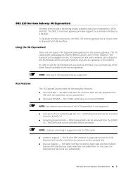
Example: Configuring a Layer 2 Circuit into a Layer 2 VPNThis example provides a step-by-step procedure and commands for configuring andverifying a Layer 2 circuit to a Layer 2 VPN. It contains the following sections:• Requirements on page 5• Overview and Topology on page 5• Configuration on page 6RequirementsThis example uses the following hardware and software components:• Junos OS Release 9.3 or later• 2 MX Series routers• 2 M Series routers• 1 T Series router• 1 EX Series router• 1 J Series routerOverview and TopologyThe logical topology of a Layer 2 circuit to a Layer 2 VPN connection is shown in Figure 1on page 5.Figure 1: Logical Topology of a Layer 2 circuit to a Layer 2 VPN ConnectionCE3J SeriesRoute ReflectorCE1PE1Layer 2 CircuitMX SeriesMX SeriesPE3T SeriesEX SeriesP1Layer 2 VPNM SeriesPE5M SeriesCE5Layer 2 VPN connection between PE3 and PE5Layer 2 circuit terminating into the Layer 2 VPN on PE5End-to-end Layer 2 interworking between CE1 and CE5g040541Copyright © 2010, <strong>Juniper</strong> <strong>Networks</strong>, Inc.5
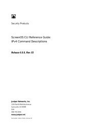
Configuring Layer 2 Circuit Into L2-VPNThe physical topology of a Layer 2 circuit to a Layer 2 VPN connection is shown in Figure2 on page 6.Figure 2: Physical Topology of a Layer 2 circuit to a Layer 2 VPN ConnectionCE3EX Seriesge-0/1/0EX Seriesge-1/0/0PE1ge-1/0/1MX Seriesxe-0/1/0xe-0/2/0xe-0/2/0xe-0/3/0J Seriesge-3/0/0xe-0/1/0xe-0/0/0MX SeriesPE3xe-0/3/0MX SeriesMX Series PE5Route ReflectorT Seriesge-0/2/0ge-0/0/0ge-1/1/0T Seriesxe-1/3/0ge-1/2/0MX Seriesxe-0/0/0ge-0//0ge-0/1/0P1 PE4 CE4M Seriesge-0/1/2ge-1/0/2PE2ge-2/0/0ge-0/2/0M SeriesCE5g040540ConfigurationNOTE: In any configuration session, it is good practice to verify periodicallythat the configuration can be committed using the commit check command.In this example, the router being configured is identified using the following commandprompts:• CE1 identifies the customer edge 1 (CE1) router• PE1 identifies the provider edge 1 (PE1) router• CE3 identifies the customer edge 3 (CE3) router• PE3 identifies the provider edge 3 (PE3) router• CE5 identifies the customer edge 5 (CE5) router• PE5 identifies the provider edge 5 (PE5) routerThis example is organized in the following sections:• Configuring Protocols on the PE and P Routers on page 7• Verification on page 116Copyright © 2010, <strong>Juniper</strong> <strong>Networks</strong>, Inc.
Example: Configuring a Layer 2 Circuit into a Layer 2 VPNConfiguring Protocols on the PE and P RoutersStep-by-StepProcedureBase ConfigurationAll of the PE routers and P routers are configured with OSPF as the IGP protocol. TheMPLS, LDP, and BGP protocols are enabled on all of the interfaces except fxp.0.Core-facing interfaces are enabled with the MPLS address and inet address.1. Configure all the PE and P routers with OSPF as the IGP. Enable the MPLS, LDP,and BGP protocols on all interfaces except fxp.0. LDP is used as the signalingprotocol on Router PE1 for the Layer 2 circuit. The following configuration snippetshows the protocol configuration for Router PE1:[edit]protocols {mpls {interface all;interface fxp0.0 {disable;}}bgp {group RR {type internal;local-address 1.1.1.1;family l2vpn {signaling;}neighbor 7.7.7.7;}}ospf {traffic-engineering;area 0.0.0.0 {interface all;interface fxp0.0 {disable;}}}ldp {interface all;interface fxp0.0 {disable;}}}2. Configure the PE and P routers with OSPF as the IGP. Enable the MPLS, LDP, andBGP protocols on all interfaces except fxp.0. BGP is used as the signaling protocolon Router PE3 for the Layer 2 VPN. The following configuration snippet shows theprotocol configuration for Router PE3:[edit]protocols {mpls {Copyright © 2010, <strong>Juniper</strong> <strong>Networks</strong>, Inc.7
Configuring Layer 2 Circuit Into L2-VPNinterface all;interface fxp0.0 {disable;}}bgp {group RR {type internal;local-address 3.3.3.3;family l2vpn {signaling;}neighbor 7.7.7.7;}}ospf {traffic-engineering;area 0.0.0.0 {interface all;interface fxp0.0 {disable;}}}ldp {interface all;interface fxp0.0 {disable;}}}Step-by-StepProcedureConfiguring Interfaces1. On Router PE1, configure the ge-1/0/0 interface encapsulation. To configure theinterface encapsulation, include the encapsulation statement and specify theethernet-ccc option (vlan-ccc encapsulation is also supported). Configure thege-1/0/0.0 logical interface family for circuit cross-connect functionality. Toconfigure the logical interface family, include the family statement and specify theccc option. The encapsulation should be configured the same way for all routers inthe Layer 2 VPN domain.[edit interfaces]ge-1/0/0 {encapsulation ethernet-ccc;unit 0 {family ccc;}}lo0 {unit 0 {family inet {address 1.1.1.1/32;}}8Copyright © 2010, <strong>Juniper</strong> <strong>Networks</strong>, Inc.
Example: Configuring a Layer 2 Circuit into a Layer 2 VPN}2. On Router PE5, configure the iw0 interface with two logical interfaces. To configurethe iw0 interface, include the interfaces statement and specify iw0 as the interfacename.[edit interfaces]iw0 {unit 0 {encapsulation ethernet-ccc;peer-unit 1;}unit 1 {encapsulation ethernet-ccc;peer-unit 0;}}3. On Router PE5, configure the logical loopback interface. The loopback interface isused to establish the targeted LDP sessions to Routers PE1 and PE5.[edit interfaces]lo0 {unit 0 {family inet {address 5.5.5.5/32;}}}Step-by-StepProcedureConfiguring the Layer 2 circuit1. On Router PE1, configure the IP address of the remote PE router with the neighborstatement. The loopback address and router ID of the PE neighbor is commonlythe neighbor’s IP address. To allow a Layer 2 circuit to be established even thoughthe maximum transmission unit (MTU) configured on the PE router does not matchthe MTU configured on the remote PE router, include the ignore-mtu-mismatchstatement.[edit]protocols {l2circuit {neighbor 5.5.5.5 {interface ge-1/0/0.0 {virtual-circuit-id 100;no-control-word;ignore-mtu-mismatch;}}}}2. On Router PE5, configure the IP address of the remote PE router. To configure theIP address of the remote PE router, include the neighbor statement and specify theIP address of the loopback interface on Router PE1. Configure the virtual circuit IDto be the same as the virtual circuit ID on the neighbor router. To allow a Layer 2Copyright © 2010, <strong>Juniper</strong> <strong>Networks</strong>, Inc.9
Configuring Layer 2 Circuit Into L2-VPNcircuit to be established even though the MTU configured on the local PE routerdoes not match the MTU configured on the remote PE router, include theignore-mtu-mismatch statement. Also disable the use of the control word fordemultiplexing by including the no-control-word statement.[edit protocols]l2circuit {neighbor 1.1.1.1 {interface iw0.0 {virtual-circuit-id 100;no-control-word;ignore-mtu-mismatch;}}3. On Router PE5, configure the Layer 2 VPN protocols by including the l2vpn statementat the [edit routing-instances routing-instances-name protocols] hierarchy level. Toconfigure the iw0 interface, include the interfaces statement and specify iw0 asthe interface name. The iw0 interface is configured under the Layer 2 VPN protocolsto receive the looped packet from the iw0.1. Protocols l2vpn is configured on RouterPE5 with a site CE5, which is configured in the BGP L2VPN. The CE1 should havecommunication to CE5, through the Layer 2 interworking configuration on RouterPE5.routing-instances {L2VPN {instance-type l2vpn;interface ge-2/0/0.0;interface iw0.1;route-distinguisher 65000:5;vrf-target target:65000:2;protocols {l2vpn {encapsulation-type ethernet;site CE5 {site-identifier 5;interface ge-2/0/0.0 {remote-site-id 3;}}site l2-circuit {site-identifier 6;interface iw0.1 {remote-site-id 3;}}}}}}4. In addition to the iw0 interface configuration, Layer 2 interworking l2iw protocolsmust be configured. Without the l2iw configuration, the l2iw routes are not formed,regardless of whether any iw interfaces are present. Within the l2iw protocols, only10Copyright © 2010, <strong>Juniper</strong> <strong>Networks</strong>, Inc.
Example: Configuring a Layer 2 Circuit into a Layer 2 VPNtrace options can be configured in the standard fashion. The minimum configurationnecessary for the feature to work is shown below.[edit]protocols {l2iw;}VerificationStep-by-StepProcedureVerifying the Layer 2 Circuit to Layer 2 VPN Connection on Router PE31. On Router PE1, use the show l2circuit connections command to verify that the Layer2 Circuit from Router PE1 to Router PE5 is Up.user@PE1> show l2circuit connectionsLayer-2 Circuit Connections:Legend for connection status (St)EI -- encapsulation invalid NP -- interface h/w not presentMM -- mtu mismatchDn -- downEM -- encapsulation mismatch VC-Dn -- Virtual circuit DownCM -- control-word mismatch Up -- operationalVM -- vlan id mismatchCF -- Call admission control failureOL -- no outgoing labelIB -- TDM incompatible bitrateNC -- intf encaps not CCC/TCC TM -- TDM misconfigurationBK -- Backup ConnectionST -- Standby ConnectionCB -- rcvd cell-bundle size bad XX -- unknownSP -- Static PseudowireLegend for interface statusUp -- operationalDn -- downNeighbor: 5.5.5.5Interface Type St Time last up # Up transge-1/0/0.0(vc 100) rmt Up Jan 3 22:00:49 2010 1Remote PE: 5.5.5.5, Negotiated control-word: NoIncoming label: 301328, Outgoing label: 300192Local interface: ge-1/0/0.0, Status: Up, Encapsulation: ETHERNETuser@PE5> show l2vpn connections2. On Router PE5, use the show l2vpn connections command to verify that the Layer2 VPN connection is Up using the iw0 peer interface of the Layer 2 circuit.Instance: L2VPNLocal site: CE5 (5)connection-site Type St Time last up # Up transl2-circuit (6) loc OR3 rmt UpJan 3 22:51:12 2010 1Remote PE: 3.3.3.3, Negotiated control-word: Yes (Null)Incoming label: 800258, Outgoing label: 800000Local interface: ge-2/0/0.0, Status: Up, Encapsulation: ETHERNETLocal site: l2-circuit (6)connection-site Type St Time last up # Up transCE5 (5) loc OR3 rmt Up Jan 3 22:56:38 2010 1Remote PE: 3.3.3.3, Negotiated control-word: Yes (Null)Incoming label: 800262, Outgoing label: 800001Copyright © 2010, <strong>Juniper</strong> <strong>Networks</strong>, Inc.11
Configuring Layer 2 Circuit Into L2-VPNLocal interface: iw0.1, Status: Up, Encapsulation: ETHERNETStep-by-StepProcedureVerifying the Layer 2 Circuit terminating into Layer 2 VPN connection1. On Router PE 5, use the show l2circuit connections command to verify that the Layer2 circuit is Up using the iw0 interface. This will be looped through the iwo.1 interfaceto the Layer 2 VPN.user@PE5> show l2circuit connectionsLayer-2 Circuit Connections:Neighbor: 1.1.1.1Interface Type St Time last up # Up transiw0.0(vc 100) rmt Up Jan 3 21:59:07 2010 1Remote PE: 1.1.1.1, Negotiated control-word: NoIncoming label: 300192, Outgoing label: 301328user@PE5>show route table mpls.02. On Router PE 5, use the show route table mpls.0 command to verify the Layer 2circuit and Layer 2 VPN routes. In the example below, the Layer 2 circuit is associatedwith LDP label 301328 and the Layer 2 VPN is associated with LDP label 800001.Notice the two iw0 interfaces that are used for the Layer 2 interworking route.mpls.0: 18 destinations, 20 routes (18 active, 2 holddown, 0 hidden)+ = Active Route, - = Last Active, * = Both0 *[MPLS/0] 5d 20:07:31, metric 1Receive1 *[MPLS/0] 5d 20:07:31, metric 1Receive2 *[MPLS/0] 5d 20:07:31, metric 1Receive299776 *[LDP/9] 2d 03:00:51, metric 1300048 *[LDP/9] 2d 03:00:49, metric 1> to 10.10.6.1 via xe-0/1/0.0, Pop300048(S=0) *[LDP/9] 2d 03:00:49, metric 1> to 10.10.6.1 via xe-0/1/0.0, Pop300192 *[L2IW/6] 19:11:05, metric2 1> to 10.10.6.1 via xe-0/1/0.0, Swap 800001[L2CKT/7] 20:08:36> via iw0.0, Pop800258 *[L2VPN/7] 19:16:31> via ge-2/0/0.0, Pop Offset: 4800262 *[L2IW/6] 19:11:05, metric2 1> to 10.10.3.1 via xe-1/1/0.0, Swap 301328[L2VPN/7] 19:11:05> via iw0.1, Pop Offset: 4ge-2/0/0.0 *[L2VPN/7] 19:16:31, metric2 1> to 10.10.6.1 via xe-0/1/0.0, Push 800000 Offset: -4iw0.0 *[L2CKT/7] 20:08:36, metric2 1> to 10.10.3.1 via xe-1/1/0.0, Push 301328iw0.1 *[L2VPN/7] 19:11:05, metric2 1> to 10.10.6.1 via xe-0/1/0.0, Push 800001 Offset: -412Copyright © 2010, <strong>Juniper</strong> <strong>Networks</strong>, Inc.
Example: Configuring a Layer 2 Circuit into a Layer 2 VPNRelatedDocumentation• Layer 2 Circuit and Layer 2 VPN Overview on page 1Copyright © 2010, <strong>Juniper</strong> <strong>Networks</strong>, Inc.13
Configuring Layer 2 Circuit Into L2-VPN14Copyright © 2010, <strong>Juniper</strong> <strong>Networks</strong>, Inc.