Download - Juniper Networks
Download - Juniper Networks
Download - Juniper Networks

Create successful ePaper yourself
Turn your PDF publications into a flip-book with our unique Google optimized e-Paper software.
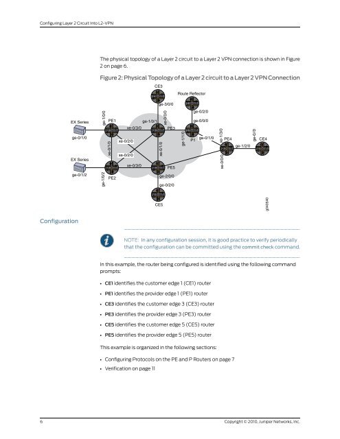
Configuring Layer 2 Circuit Into L2-VPNThe physical topology of a Layer 2 circuit to a Layer 2 VPN connection is shown in Figure2 on page 6.Figure 2: Physical Topology of a Layer 2 circuit to a Layer 2 VPN ConnectionCE3EX Seriesge-0/1/0EX Seriesge-1/0/0PE1ge-1/0/1MX Seriesxe-0/1/0xe-0/2/0xe-0/2/0xe-0/3/0J Seriesge-3/0/0xe-0/1/0xe-0/0/0MX SeriesPE3xe-0/3/0MX SeriesMX Series PE5Route ReflectorT Seriesge-0/2/0ge-0/0/0ge-1/1/0T Seriesxe-1/3/0ge-1/2/0MX Seriesxe-0/0/0ge-0//0ge-0/1/0P1 PE4 CE4M Seriesge-0/1/2ge-1/0/2PE2ge-2/0/0ge-0/2/0M SeriesCE5g040540ConfigurationNOTE: In any configuration session, it is good practice to verify periodicallythat the configuration can be committed using the commit check command.In this example, the router being configured is identified using the following commandprompts:• CE1 identifies the customer edge 1 (CE1) router• PE1 identifies the provider edge 1 (PE1) router• CE3 identifies the customer edge 3 (CE3) router• PE3 identifies the provider edge 3 (PE3) router• CE5 identifies the customer edge 5 (CE5) router• PE5 identifies the provider edge 5 (PE5) routerThis example is organized in the following sections:• Configuring Protocols on the PE and P Routers on page 7• Verification on page 116Copyright © 2010, <strong>Juniper</strong> <strong>Networks</strong>, Inc.