Dangerous Power G3 Spec R Manual - Mcarterbrown.com
Dangerous Power G3 Spec R Manual - Mcarterbrown.com
Dangerous Power G3 Spec R Manual - Mcarterbrown.com
- No tags were found...

You also want an ePaper? Increase the reach of your titles
YUMPU automatically turns print PDFs into web optimized ePapers that Google loves.
W W W . D A N G E R O U S P O W E R . C O MW W W . D A N G E R O U S P O W E R . C O M
WARNINGIMPORTANT SAFETY INSTRUCTIONS AND GUIDELINES!WARNINGIMPORTANT SAFETY INSTRUCTIONS AND GUIDELINES!1. The DP <strong>G3</strong> <strong>Spec</strong>-R is NOT A TOY. Treat it withthe same respect and care you would a firearm.2. Carelessness, misuse, and failure to adhereto the warning and guidelines printed in thisOwner’s <strong>Manual</strong> may result in property damage,injury, or death. User assumes all risksassociated with use of the DP <strong>G3</strong> <strong>Spec</strong>-R.3. Always ensure that proper safety gear - eyes,face, ear, and head protection - conforming toASTM standard F1776 (USA) or CE (Europe)are worn at all times when paintballs are withinrange.4. Persons under the age of 18 must have adultsupervision at all times during use of the <strong>G3</strong><strong>Spec</strong>-R, or any paintball firing device.5. Observe all local and national laws regardingrules and regulations.6. The <strong>G3</strong> <strong>Spec</strong>-R should only be used on apermitted and regulated paintball field wheresafety rules and guidelines are strictly enforced.7. Only use <strong>com</strong>pressed air or nitrogen. DO NOTUSE CO2!8. Only use high quality, .68 caliber paintballs.9. Never point your <strong>G3</strong> <strong>Spec</strong>-R at an unintendedtarget.10. Always treat your <strong>G3</strong> <strong>Spec</strong>-R as if it wereloaded.11. Keep your <strong>G3</strong> <strong>Spec</strong>-R turned OFF until ready touse.12. Always measure the velocity of paintballs fromyour <strong>G3</strong> <strong>Spec</strong>-R with a suitable chronographdevice before play.13. Never look down the barrel or breech area of the<strong>G3</strong> <strong>Spec</strong>-R without first ensuring that the markeris switched to the OFF position, with NO AIR inthe marker.NOTE- SEE NOTE ON PAGE 3 FOR DIRECTIONS ONREMOVING RESIDUAL AIR FROM A POWERED ‘OFF”MARKER.14. Never put any body parts or foreign objects intothe breech or feed tube.15. Always use the supplied barrel cover when your<strong>G3</strong> <strong>Spec</strong>-R is not in use at the field. Doing sowill help secure the safety of yourself and thosearound you.16. Never allow pressurized gas to <strong>com</strong>e intocontact with your body. Serious harm, injury, ordeath may occur.17. When not in use, always turn your <strong>G3</strong> <strong>Spec</strong>-R tothe OFF position.18. Promptly remove any paintballs from your <strong>G3</strong><strong>Spec</strong>-R when not in use.19. Always remember to remove residual air fromyour <strong>G3</strong> <strong>Spec</strong>-R before attempting maintenanceor service.20. Always remember to remove residual air fromyour <strong>G3</strong> <strong>Spec</strong>-R before storage ortransportation.NOTE- POWERING ‘ OFF’ THE MARKER WILL NOTAUTOMATICALLY REMOVE RESIDUAL AIR. TOSAFELY REMOVE RESIDUAL AIR, PLEASE DO THEFOLLOWING:A. Remove loader and paintballs from marker.B. Turn Eye Sensors to the OFF position.C. Point marker in a safe direction.D. Fire marker until all residual gas is removed.21. Always store your <strong>G3</strong> <strong>Spec</strong>-R in a safe place.22. Do not discard the Owner’s <strong>Manual</strong>. In the eventof transfer or resale, this guide must ac<strong>com</strong>panythe marker.23. When in doubt, ALWAYS seek expert adviceby contacting a reputable airsmith familiar withpaintball markers, or by contactingDP Engineering’s Customer Service Staff.02 W W W . D A N G E R O U S P O W E R . C O M03
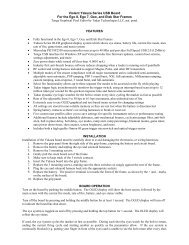
FEATURES1. Innovative and highly efficient o-ring-less bolt system.2. Extremely light weight body (1.79lbs with barrel, patented RAPS ASA, clamping feedneck and battery).3. Increased air efficiency.4. High precision light weight 3-D milled aluminum alloy body and accents.5. Stocked fully programmable micro-switch board.6. Adjustable magnetic ball bearing trigger.7. Light weight interlocking ported two piece barrel.8. Patented low profile clamping feedneck.9. Patented flip lever Rapid Air Pressurizing System (RAPS) ASA.07
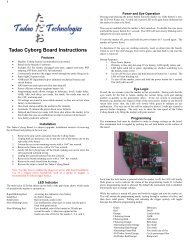
<strong>G3</strong> <strong>Spec</strong>-R BOLT SYSTEMBARREL COVER<strong>G3</strong> <strong>Spec</strong>-R BODYCAP• Place the barrel cover over the tip of the barrel and pull the elastic band over the feedneck or back of markerbefore attaching paintball loader.WARNINGFOR YOUR SAFETY, ALWAYS HAVE THE BARREL COVER ON WHEN NOT PLAYING.BOLTINSTALLING THE BATTERYO-RINGDVB (DUMP VALVE BOLT)• Carefully remove the 2 hexagonal screws (3/32”) holding the left panel in place.• Locate battery harness and attach 9V battery to the connector pad. Do not use force!• Replace battery in grip frame as shown in illustration.• Replace grip frame and screws. Do not over tighten screws!BACK POSITIONFORWARD POSITION12 W W W . D A N G E R O U S P O W E R . C O M13
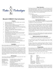
TRIGGER ADJUSTMENTBOARD• There are three (3) adjustment screws (marked A, B and C) to adjust the trigger on the <strong>G3</strong> <strong>Spec</strong>-R.• Screw A (5/64”) adjusts the amount of trigger travel prior to the marker firing. Turning this screw clockwise willreduce the amount of trigger travel. Turning this screw counterclockwise will increase the amount of triggertravel.• Screw B (5/64”) sets the amount of trigger travel after the marker has been fired. Turning the screw clockwisewill reduce the amount of trigger travel. Turning the screw counterclockwise will increase the amount of triggertravel.• Screw C (3/32”) adjusts the strength of the trigger’s return to rest by either reducing or increasing themagnetic pull. Turning this screw counterclockwise will decrease the strength. Turning this screw clockwisewill increase the strength. Do not turn the screw too far - doing so may weaken the magnetic pull and preventthe trigger from being able to fully return to rest.NOTEBe careful not to turn the screw too far in either direction, as doing so may pushthe trigger past the firing point and cause operational failure.ABCTRIGGERFires the marker.FIRING MODE OPERATIONFiring mode Invokes programmingmode at power up.PROGRAMING MODEOPERATIONProgramming mode cyclesthrough setpoints and enterssetpoint values via pulls.LEDPOWER ONGreen light indicate battery levelok, Red light indicate batterylevel low.POWER BUTTONPOWER ONPress and hold until illuminates.Release and marker is ready tofire.POWER OFFPress and hold 2 seconds untilboard turns off. Release andmarker is off.EYE CONTROLTap to toggle eye sensor on/off.18 W W W . D A N G E R O U S P O W E R . C O M19
PROGRAMMING YOUR <strong>G3</strong> <strong>Spec</strong>-RPROGRAMMING YOUR <strong>G3</strong> <strong>Spec</strong>-R (CONTINUED)1. POWER2. TOURNAMENT LOCKPOWER ON• DIP switch 1 set to “ON”. Modes cannot be set withoutunlocking tournament lock.ON• Press and hold down Button A to turn on the marker witheye sensors on.LIGHT WINDOW• Dip Switch 2 is non functional.• When battery voltage is lower than 7.2V, the indicatorlight will flash red. When battery voltage is over 7.2Vthen the indicator light will flash green.1 2• When the <strong>G3</strong> <strong>Spec</strong> R eye sensors are on the indicatorwill blink a slow green light (1 blink/0.5 seconds). Theindicator light will remain solid green when paintball is inthe breech.• To turn the eye sensors off, press and release Button A.When the <strong>G3</strong> <strong>Spec</strong> R eye sensors are off the indicatorlight will blink a quick green light (1 blink/0.2 seconds)POWER OFFBUTTON A3. CONFIGURATION MODE• To enter programming mode, marker must first be turned off anddip switch 1 must be set to OFF position.• Pull and hold down trigger then press Button A for 2 seconds.Release Button A and then trigger and the indicator light willflash multiple colors and stop at solid red which indicatesprogramming mode.ON1 2• Press and hold down Button A for 2 seconds before indicator light turns off.• The marker will shut down automatically after being idle for 20 minutes. The marker will retain the lastadjusted set points whether it shutdown automatically, manually or by removing the battery.20 W W W . D A N G E R O U S P O W E R . C O M21
PROGRAMMING YOUR <strong>G3</strong> <strong>Spec</strong>-R (CONTINUED)RESETTo reset the marker to manufacturing default settings, press and hold down the trigger then press and hold downthe on/off button. Release the on/off button and hold on to the trigger for 10 seconds until yellow light appears.4. EXAMPLE SETTING FROM SEMI TO MILLENNIUM1. Turn off the marker before entering the setting mode and switch DIP 1 to the OFF position2. Pull and hold the trigger then press power button to turn on the marker. Release the power button thentrigger, the LED will be Red which indicates the Rate of Fire setpoint.3. Pull trigger once to proceed to the next function selection mode, when the LED turns green then the functionalmodel will be at the Firing Mode. Press the POWER button once to enter the observation model which willdisplay the last setting. The LED will be flash the value that previous set.• If pull the trigger at the observation mode then will be skip to the next function.• If the original setting is at 4 then green LED 4 times, so on and so forth.4. Follow-up to Step (3), then press POWER button once (LED will blink red green and yellow in a secondindicating of access to adjustable settings mode.5. Following steps (4), in accordance with pulling the trigger 4 times (it will set the value to 4 [Millennium Mode].Press the power button one time to indicate the set and to leave the adjustment mode back to Step 3observation mode. The last settings well be reflected in the blinking of the indicator light.6. Then look at the other function whether or not to continue to choose or turned off board to leave the set mode.24W W W . D A N G E R O U S P O W E R . C O M
CARE AND MAINTENANCECLEANING THE EYE-SENSOR BREAK BEAM SYSTEMRoutine care and maintenance for your <strong>Dangerous</strong> <strong>Power</strong> <strong>G3</strong> <strong>Spec</strong>-R will ensure many years of high performanceand enjoyment. When in doubt, always seek the assistance of a certified technician from a reputable pro shop, orcontact <strong>Dangerous</strong> <strong>Power</strong> Customer Service.DEGASSING the <strong>G3</strong> <strong>Spec</strong>-RAlways be sure to <strong>com</strong>pletely de-gas your marker before performing maintenance or service repair. Carefully followthe instructions below in sequence to ensure that all remaining air has been removed from the entire marker:1. Flip the RAPS TM ASA to the ‘Off’ position. This disconnects the air system from the marker.2. Remove the paintball loading device and check to make sure there are no paintballs within the breech.3. Unscrew the air system from the RAPS TM ASA.The function of the break beam sensor eyes is to allow the firing circuit to ‘time’ the activation of the solenoid. Thisprevents ‘chopping’ of paint, which is caused by the bolt cycling within the breech without the paintball beingactually seated in the proper firing position. When the eye sensors are ON, the gun will not fire if the beam doesnot sense a paintball. To ensure proper function, the eye sensors should be cleaned after every other use, or whenpaintballs have been broken within the marker. More frequent cleaning may be necessary when using paintballsthat have ‘oily residue’ on the surface of the shell. To avoid malfunction, always use fresh and clean paint from areliable manufacturer.To clean the eyes:1. Locate the eye cover plates on either side of your <strong>G3</strong> <strong>Spec</strong>-R body. (SEE PIC A)2. Using provided allen key wrench (5/64”), carefully remove the eye cover screw on one side by inserting ballpoint tip and turning wrench handle counterclockwise. (SEE PIC B)3. Lift eye cover plate, exposing eye wires, spring, and ball detent. (SEE PIC C)4. Point the marker in a safe direction, and then fire 1-2 shots to remove air from the OPR. Be aware that themarker may still fire without any an air system attached.5. <strong>Power</strong> OFF the marker.A B C26 W W W . D A N G E R O U S P O W E R . C O M27
CLEANING THE EYE-SENSOR BREAK BEAM SYSTEM(CONTINUED)CLEANING THE BALL DETENTS4. Carefully life eye wires and pull out the eye sensors from the socket. Be careful not to lose the spring and theball detent. (SEE PIC D)5. With a cotton swab, gently wipe the back and front side of the eye sensor and the eye socket to remove anydebris or residue. (SEE PIC E)6. Replace eye sensors back to original position. Be sure the eyes are aligned correctly and facing the directionof the breech.7. Replace eye cover plate in original position and gently tighten eye cover screws clockwise. DO NOT OVER-TIGHTEN! (SEE PIC F)8. Repeat the same procedure on the other side.The ball detents and spring should be inspected during the cleaning of the eye sensors. Replace these partsshould you notice any damage, no matter how slight.1. Locate the eye cover plates on either side of your <strong>G3</strong> <strong>Spec</strong>-R body.2. Using provided allen key wrench (5/64”), carefully remove the eye cover screw on one side by inserting ballpoint tip and turning wrench handle counterclockwise. (SEE PIC A)3. Lift eye cover plate, exposing eye wires, spring, and ball detent. (SEE PIC B)4. Remove spring by carefully lifting it up by hand or with the aid of small tweezers. (SEE PIC C)HELPFUL HINTDO NOT PULL ON THE EYE WIRES. USE A SMALL PICK OR SCREW DRIVER TO GENTLY LIFT THEWIRES UP. THIS WILL LIFT THE EYE SENSORS OUT OF THE EYE SOCKET.DEFABC28 W W W . D A N G E R O U S P O W E R . C O M29
CLEANING THE BALL DETENTS (CONTINUED)OPERATING PRESSURE REGULATOR (OPR)DISASSEMBLY AND MAINTENANCE5. Place finger within breech, and gently push on the detent from the inside of marker body. Remove ball detent.(SEE PIC D)6. Check the spring for proper tension and the ball detent for any damage. Replace with new part(s) ifnecessary.7. With a cotton swab, clean the spring, ball detent, and detent groove. (SEE PIC E)8. Replace detent back to original position, with the circular side down towards the breech.9. Replace spring over the detent in the original position.10. Replace eye cover plate in original position and gently tighten eye cover screws clockwise. DO NOT OVER-TIGHTEN! (SEE PIC F)11. Repeat the same procedure on the other side.The OPR regulates the amount of air-flow, which determines paintball velocity. Regular inspection and cleaning ofyour OPR is an essential part of keeping your <strong>G3</strong> <strong>Spec</strong>-R running in top condition. Follow the easy steps outlinedbelow to ensure that your OPR remains trouble-free.GENERAL DISASSEMBLY OF OPR1. Before disassembly of your regulator, be sure to disconnect the macro-line hose from the elbow fittingattached to your regulator. This is ac<strong>com</strong>plished by pulling back on the collet of the elbow fitment, whilesimultaneously pulling the macro-line out to remove.2. With a firm hold on the OPR body, unscrew by hand the entire unit in a counterclockwise direction. If the OPRunit is difficult to turn by hand, a rubber strap wrench available in most hardware stores may be used.(SEE PIC A)DEFANOTEDO NOT UNSCREW BY USING WRENCH ORPLIERS, AS DOING SO MAY SCRATCH ANDDAMAGE THE ANODIZED SURFACE.30 W W W . D A N G E R O U S P O W E R . C O M31
OPERATING PRESSURE REGULATOR (OPR)DISASSEMBLY AND MAINTENANCE (CONTINUED)OPERATING PRESSURE REGULATOR (OPR)DISASSEMBLY AND MAINTENANCE (CONTINUED)3. By hand or with the assistance of a strap wrench, unscrew the OPR Top Housing Ring from the OPR MainBody Housing. (SEE PIC B)4. Place finger inside OPR Piston, and lift to remove.(SEE PIC C)6. Using ‘C-clip’ pliers (not supplied), carefully remove the C-clips from the OPR Bottom housing. Make sure notto scratch any anodized surfaces. (SEE PIC E . F)7. Using the supplied allen wrench key (1/4”), remove the Regulator Adjustment Screw. (SEE PIC G)5. Carefully remove OPR Piston Washers from inside OPR Main Body Housing by turning it upside down on aflat surface. (SEE PIC D)NOTEPLEASE NOTE THE PROPER STACKING ORDER ANDDIRECTION OF THE SHIMS FOR CORRECTREASSEMBLY!SHIM STACKB C DEF<strong>G3</strong>2 W W W . D A N G E R O U S P O W E R . C O M33
OPERATING PRESSURE REGULATOR (OPR)DISASSEMBLY AND MAINTENANCE (CONTINUED)OPERATING PRESSURE REGULATOR (OPR)DISASSEMBLY AND MAINTENANCE (CONTINUED)CLEANING AND MAINTENANCE OF OPR1. Remove all visible debris and dirt with a lightly dampened and clean cotton cloth. Take care not to scratch thesurface of any regulator parts.2. Lightly apply a small amount of DP-40 lubricant to the tip of a cotton swab. (SEE PIC A)3. Apply lubricant to the o-ring located on the base of the Regulator Adjustment Screw. (SEE PIC B).4. Apply lubricant to the o-ring located on the base of the OPR Piston. (SEE PIC C)5. Apply lubricant to the o-ring located on the stem of OPR Piston. (SEE PIC D)6. Apply lubricant to the 2 o-rings located on the OPR Top Housing Ring. (SEE PIC E . F)Be careful not to apply excess pressure, as doing so may damage sensitive parts and/or strip delicate threads.NOTECAREFULLY INSPECT O-RING PRIOR TO APPLYING LUBRICANT. REPLACE IF O-RING APPEARSWORN, CRACKED, TORN, OR DAMAGED.ABCDEF34 W W W . D A N G E R O U S P O W E R . C O M35
DISASSEMBLY AND MAINTENANCE OF DUMPVALVE BOLT AND DUMP VALVE PLUGDISASSEMBLY AND MAINTENANCE OF DUMPVALVE BOLT AND DUMP VALVE PLUG (CONTINUED)1. Unscrew front of barrel from <strong>G3</strong> <strong>Spec</strong>-R body.2. Use supplied allen key wrench (1/4”) on the back of marker and unscrew back cap. (SEE PIC A)3. Remove Dump Valve Plug from marker body. (SEE PIC B)4. Remove Dump Valve Bolt from marker body. It may be necessary to use your finger to pull it or push it out, asillustrated. (SEE PIC C)5. Wipe off all visible debris and grime from the Dump Valve Bolt, Dump Valve Plug and internal of <strong>G3</strong> <strong>Spec</strong>-Rbody with a soft dampened cotton cloth and cotton swab.4. Lightly apply DP-40 lubricant to the tip of a cotton swab.5. Apply lubricant directly onto the Dump Valve Bolt. (SEE PIC D)6. Apply lubricant to the two o-rings located on the Dump Valve Plug. (SEE PIC E . F)NOTETHE ABOVE STEPS ARE ALL THAT ARE REQUIRED FOR NORMAL BOLT MAINTENANCE. PROCEEDFURTHER TO ACCESS SOLENOID AND TRIGGER.WARNINGNEVER USE FORCE DURING DISASSEMBLY OR REASSEMBLY. ALWAYS SEEK ASSISTANCE FROM AQUALIFIED AIRSMITH OR CONTACT DP ENGINEERING CUSTOMER SERVICE IF YOU ARE UNCERTAINOF ANY INSTRUCTIONS DESCRIBED IN THIS MANUAL.ABCDEF36 W W W . D A N G E R O U S P O W E R . C O M37
SEPARATING <strong>G3</strong> <strong>Spec</strong>-R BODY FROM TRIGGERFRAME1. Locate screw underneath <strong>G3</strong> <strong>Spec</strong>-R body, between OPR and Trigger Guard. Using (3/32”) allen key wrench,loosen Connector Screw #1 by turning it counterclockwise. (SEE PIC A)2. Locate Connector Screw #2 behind back cap. Using (5/32”) allen key wrench, loosen screw by turning itcounterclockwise. (SEE PIC B)3. Separate the <strong>G3</strong> <strong>Spec</strong>-R body from the trigger frame. (SEE PIC C)SOLENOID MAINTENANCEThe <strong>G3</strong> <strong>Spec</strong>-R solenoid is a delicate electronic <strong>com</strong>ponent that requires minimal maintenance or service. DPEngineering does not re<strong>com</strong>mend frequent cleaning of this part, or its internals. The following instructions areprovided for reference and for expert airsmiths only.1. Once the <strong>G3</strong> <strong>Spec</strong>-R body and trigger frame are separated, locate the solenoid within the marker body. Notethe wiring harness connecting the solenoid to the main circuit board. (SEE PIC A)2. Gently secure the base of the connectors and pull up to remove the plugs. DO SO ONE AT A TIME. It maybe helpful to use needle nose pliers. Note the location and direction of the connectors on the circuit board forreassembly. (SEE PIC B . C)3. With the connectors dislodged, turn the <strong>G3</strong> <strong>Spec</strong>-R body so that the underside is facing up.ABCABC38 W W W . D A N G E R O U S P O W E R . C O M39
SOLENOID MAINTENANCE (CONTINUED)SOLENOID MAINTENANCE (CONTINUED)4. Using (5/65”) allen wrench key, locate and remove both screws securing the solenoid to the marker body.(SEE PIC D . E)5. Once both screws are removed, gently lift and remove the solenoid. (SEE PIC F)6. Place solenoid on a flat surface, with the wiring harness side facing down and solenoid disassembly screwfacing up.7. Secure base of solenoid casing with an adjustable wrench (not provided). Using a slotted (flathead)screwdriver, remove screw carefully by turning itcounterclockwise. Be extremely careful not to strip the screw.(SEE PIC G)8. Remove solenoid spring. (SEE PIC H)9. With thin tweezers or needle nose pliers, carefully remove the solenoid piston by gently securing the tipand pulling it out. (SEE PIC I)10. Carefully inspect and clean solenoid piston o-rings. Make sure the o-rings are not cracked, broken, or showsigns of wear. Replace parts if necessary.11. With a cotton swab, lightly apply a small amount of DP-40 lube to the solenoid piston assembly. (SEE PIC J)12. Replace in reverse order.WARNINGNEVER USE FORCE WHEN REMOVING OR REINSTALLING THE SOLENOID AND ITS SENSITIVEINTERNALS. BE CAREFUL NOT TO BEND, TWIST, OR BREAK DELICATE WIRES, AS DOING SO MAYRENDER THE UNIT INOPERATIVE OR CAUSE IT TO MALFUNCTION.DEFGHIJ40 W W W . D A N G E R O U S P O W E R . C O M41
REMOVING TRIGGER FROM FRAME1. Locate the two trigger adjustment screws. Use (5/64”) allen key wrench to loosen and remove both screws byturning them counterclockwise. Be careful not to misplace the screws. (SEE PIC A . B)2. Locate trigger removal screw. Use (3/32”) allen key wrench to loosen and remove screw by turning itcounterclockwise. Carefully pull out screw. Note that the latter part of the screw is a bolt, which the triggerhinges upon. (SEE PIC C . D)3. Remove trigger assembly by lifting it up and out of <strong>G3</strong> <strong>Spec</strong>-R trigger frame. (SEE PIC E)RAPS FLIP LEVER ASAREMOVAL AND MAINTENANCEThe RAPS TM ASA was designed to be virtually maintenance free. However, it may be necessary to occasionallyclean and inspect for debris or damage, as either may cause malfunction or leaking of air.1. Remove macro-line from RAPS TM ASA. (SEE PIC A)2. Remove butterfly grip panels from trigger frame. (SEE PIC B)3. Disconnect solenoid wiring harness from circuit board. (SEE PIC C)4. Locate the three screws securing circuit board to trigger frame and unscrew using a crosshead (Phillips)screwdriver. Carefully remove the circuit board from the trigger frame. (SEE PIC D)AB C DEAB C D42 W W W . D A N G E R O U S P O W E R . C O M43
RAPS FLIP LEVER ASAREMOVAL AND MAINTENANCE (CONTINUED)RAPS FLIP LEVER ASAREMOVAL AND MAINTENANCE (CONTINUED)5. Locate front and back screws within grip frame as illustrated, and unscrew with (3/32”) allen key wrench.(SEE PIC E . F)6. Slide RAPS TM ASA forward on rail to remove from frame. (SEE PIC G)7. Locate hex screw on RAPS TM ASA casing.8. Using (5/64”) allen key wrench, loosen and remove screw by turning it counterclockwise. (SEE PIC H)11. Use a lightly dampened cloth and/or cotton swab to remove debris or grime from all RAPS TM ASA<strong>com</strong>penents, including the piston, spring, lever, and casing. (SEE PIC I)12. Clean and inspect o-ring located on the base of the piston. Replace o-ring if it appears worn, cracked, ordamaged. Using a cotton swab, apply a small amount of DP-40 lubricant on the o-ring. (SEE PIC J)13. Make sure the spring is properly seated on the piston, then reassemble the RAPS TM ASA in the reverse orderof assembly. (SEE PIC K)9. Remove RAPS TM lever and piston from RAPS TM casing as shown.10. Check spring for proper tension. Replace if worn or damaged.WARNINGREMEMBER TO DE-GAS THE <strong>G3</strong> <strong>Spec</strong>-R BEFORE SERVICING THE RAPS TM ASA. FOLLOWINSTRUCTIONS PREVIOUSLY OUTLINED ON PAGE 41 TO SAFELY AND PROPERLY REMOVE EXCESSAIR FROM THE MARKER.EFGHIJK44 W W W . D A N G E R O U S P O W E R . C O M45
TROUBLESHOOTINGPROBLEM POSSIBLE CAUSE SOLUTIONPROBLEM POSSIBLE CAUSE SOLUTION<strong>G3</strong> <strong>Spec</strong> R will notturn on<strong>G3</strong> <strong>Spec</strong> R will notfireNot activatedLow battery powerBattery is connected incorrectly tothe PC boardLow battery powerLow air pressureSolenoid may be out of placeHold down operating button for more than 4secondsReplace with fresh batteryCheck to see if the battery cable is connectedcorrectly to the terminalReplace with fresh batteryRefill the air systemOpen grip andpress solenoid forwardAir leaking frombarrel areaPaintball breakingout of the barrelPaintball choppinginternallyBolt cap o-ring is wornInternal o-ring is worn or damagedBarrel size does not match paintball’sBall detent is wornSensor system is not onLow battery powerChange o-ringChange o-ringThe stock barrel size is 0.690,change ifnecessaryChange ball detentSwitch it to ONReplace with fresh batteryHPR pressure is too lowAdjust HPR pressure without paintball presentPROBLEM POSSIBLE CAUSE SOLUTION<strong>G3</strong> <strong>Spec</strong> R will notfire with sensorsystem on<strong>G3</strong> <strong>Spec</strong> R will notcycle <strong>com</strong>pletelyNo paintball presentSensor system is uncleanBroken paintball insideBall detent is damagedAir pressure is too lowDwell time is too shortLow battery powerBolt o-ring is wornBolt o-ring lubricant is exhaustTurn on the loaderRemove and clean sensor eyeRefer to bolt maintenanceChange ball detentAdjust the operating pressure to 150 to 200 psiSee“dwell adjust system”Change batteryChange o-ringLubricate the o-ring with Dow-55 lubricant46 W W W . D A N G E R O U S P O W E R . C O M47
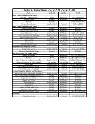
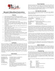
PARTS DIAGRAM AND TABLENO ITEM NUMBER O’ty NOTENO ITEM NUMBER O’ty NOTE1 20-B01265-301-PSPE0B 145 20-B30854-301-PSPE0B 12 20-F01540-000-PFUS0A 2 Ø18.77*Ø1.7846 20-W60010-000-PREV0B 23 20-F01730-000-PTHR7A 2 Ø17.17*Ø1.7847 20-W63020-000-PREV0B 1 Ø3*T34 20-F01800-000-PSPE0B 1 Ø19*Ø248 20-W11042-000-PREV0B 1 #10-32UNF-6L5 20-A40130-305-PSPE0B 149 20-H03210-000-PSPE0B 1 #3-56UNF-15L6 20-B10332-305-PSPE0B 150 20-W11012-000-PFUS8A 2 #8-32UNC7 20-F05050-000-PSPE0B 151 20-W23670-000-PSPE0B 18 20-A40140-301-PSPE0B 152 20-W10840-000-PFUS0A 3 #3-56UNF-5/32”L9 20-B10343-301-PSPE0B 153 20-W23510-000-PFUS0A 110 20-E10170-000-PT00 154 20-B10352-300-PSPE0B 111 20-F01810-000-PSPE0B 1 Ø13*Ø255 20-F10160-000-PSPE0B 112 20-F01550-000-PFUS0A 2 Ø21.95*Ø1.7856 20-W11040-000-PSPI0B 2 #10-32UNF-5/16”L13 20-B25642-301-P<strong>G3</strong>00B 157 20-A01290-301-P<strong>G3</strong>00B 114 20-B16133-301-P<strong>G3</strong>00B 158 20-E01130-000-PFUS0A 115 20-H03150-000-P<strong>G3</strong>00B 159 20-H05540-000-P<strong>G3</strong>00B 116 20-H05560-000-PFUS0A 160 20-F01590-000-PFUS0A 1 Ø3.69*Ø1.7817 20-C25030-104-P<strong>G3</strong>00B 161 20-G10250-000-PFUS0A 118 20-B30674-301-P<strong>G3</strong>00B 162 20-B25635-301-P<strong>G3</strong>00B 119 20-W10790-000-PFUS0A 2 #3-56UNF-13.3L63 20-W10810-000-PFUS0A 1 #3-56UNF-17.3L20 20-A06192-305-PIQ00L 164 20-W10560-000-PM31 1 1/8”-27NPT-6.5L21 20-W10780-000-PFUS0A 4 #3-56UNF-19.8L65 20-B30684-301-P<strong>G3</strong>00B 122 20-C20040-104-PFUS0A 166 20-A01130-104-PT00 2 1/8”NPT 牙23 20-F01780-000-P<strong>G3</strong>00B 3 Ø2*Ø167 20-A13890-610-PSPE0B 124 20-A06170-000-PSPI0B 168 20-C10122-000-P<strong>G3</strong>00B 225 20-F01480-000-PFUS0A 1 Ø6*Ø169 20-E05250-610-PSPE0B 126 20-C01042-104-PFUS0A 170 20-H03180-000-PREV0B 4 #8-32UNC-5/16”L27 20-F01470-000-PFUS0A 1 Ø7.5*Ø171 20-A20290-301-PSPE0B 128 20-C20053-104-PTHR7A 172 20-B25683-301-PSPE0B 129 20-G10230-000-PFUS0A 173 20-F01510-000-PFUS0A 1 Ø14*Ø1.7830 20-B20242-305-PTHR7A 174 20-B10302-305-P<strong>G3</strong>LEH 131 20-F01700-000-PFUS0A 4 Ø2*Ø175 20-F01570-000-PFUS0A 1 Ø4.47*Ø1.7832 20-H05480-000-PTHR7A 176 20-W20090-000-PFUS0A 833 20-G10220-000-PFUS0A 177 20-B16233-301-PSPE0B 134 20-H03110-000-PFUS0A 178 20-F01760-000-PTHR7A 2 Ø15.6*Ø1.7835 20-W10930-000-PTHR7A 2 #5-40UNC-3/16”L79 20-B16103-301-PSPI0B 136 20-H03190-000-PREV0B 2 #8-32UNC-12L80 20-W10960-000-PTHR7A 1 #10-32UNF-4.76L37 20-E01150-000-PSPI0B 281 20-H05523-000-P<strong>G3</strong>LEH 1 OPR38 20-G10300-000-PSPI0B 282 20-F01580-000-PFUS0A 1 Ø9.25*Ø1.7839 20-W23600-000-PSPI0B 183 20-W53010-000-PFUS0A 140 20-B30834-301-PSPE0B 184 20-F01820-000-PSPE0B 1 Ø12.42*Ø1.7841 20-B30844-301-PSPE0B 185 20-B16244-301-PSPE0B 142 20-W11020-000-PSPI0B 2 #3-56UNF-4L86 20-B15942-301-PT00 143 20-B05285-301-PSPE0B 187 20-E02092-000-P031 1 Ø1/4”*130L4844 20-A60220-301-PSPE0B 149
STATEMENT OF LIABILITYThe manufacturer assumes no responsibility for this product’s safe operation upon sale or distribution. PROPERTYDAMAGE, BODILIY INJURY, OR DEATH could occur due to misuse, abuse or failure to follow the manufacturer’sinstructions stated in this manual. The manufacturer will assume no responsibility for physical injury or propertydamage resulting from the use of this marker. The information in this document is subject to change without priornotice. The manufacturer assumes no responsibility for any errors that may appear in this document.DISCLAIMERNotice is hereby given that this owner’s manual is part of the article owned in whole by the manufacturer, knownas indicated by this disclaimer and all illustrations within the manual. All rights for manufacturing and reproducingof such articles or any part thereof are reserved by the manufacturer. Neither said article nor any part thereof maybe manufactured or reproduced in any way except by the written authorization of the manufacturer. All proprietarytruths and information are the sole property of the manufacturer.LIMITED WARRANTYDANGEROUS POWER TM warrants this <strong>G3</strong> <strong>Spec</strong>-R paintball marker, to the initial retail purchaser, to be free fromdefect in original materials and/or workmanship for twelve (12) months from the original date of purchase, with thefollowing exceptions:1. Disposable parts (batteries, o-rings, seals, micro switch, air pressure hose, rubber and/or plastic materialparts, etc.) are not included in this limited lifetime warranty.2. Electronic parts on this marker are fully warranted for 30 days from the original date of purchase.3. Bolt and striker systems of this marker are fully warranted for 6 months from the original date of purchase.4. Surface damages (scratches and nicks) or operation failure due to accident, neglect, modification, normalwear, operator error, maintenance by anyone other than an authorized dealer or agent, misuse, improperdisassembly and reassembly, are expressly not covered under this warranty.Purchaser is responsible for all rendered services not covered under this limited warranty, including any applicableshipping costs, labor, and/or installation.DANGEROUS POWER TM reserves the right to determine the legitimacy of claimed defective original parts andtheir eligibility for coverage under the terms of this warranty. DANGEROUS POWER TM , its authorized dealers,affiliates, and/or agents, will not be held liable under this warranty, state, federal, or <strong>com</strong>mon law for any productfailure, personal injury, or property damage resulting from improper use and/or alteration of this product. Anyattempt to alter the trigger assembly will instantly void your warranty and may result in serious injury. Any attemptto alter basic marker parts without prior written consent from the manufacturer will result in automatic default of allexpressed warranties.This limited warranty is non-transferable and is valid only upon presentation of a <strong>com</strong>pleted warranty registrationcard and original proof of purchase. There are no other warranties or guarantees, expressed or implied, made bythe manufacturer on this paintball marker.Paintball markers are non-refundable and are not subject to exchange frommanufacturer.50 W W W . D A N G E R O U S P O W E R . C O M51
P r o d u c t R e g i s t r a t i o n C a r dFill out all of the information below <strong>com</strong>pletely. To activate your warranty, visit www.dangerouspower.<strong>com</strong>and click on “SUPPORT” to register your product within 7 days of purchase. Keep this card and your receiptor proof of purchase - you will be asked to include both when sending in your product for warranty service.Name ___________________________________________________________________Address __________________________________________ Apt/Suite #______________City _________________________ State _________ Province _____________________Zip/Postal Code _________ County ______________ Country ______________________Phone (_____) ________________Fax (_____) _______________________________Email ___________________________________________________________________Name of Product Purchased _________________________________________________Date of Purchase __________ (dd/mm/yy) Product Color _________________________Place of Purchase_________________________________________________________Product Serial Number (if applicable) __________________________________________I guarantee all of the information <strong>com</strong>pleted above to be true and correct to the best of myknowledge.Signature ________________________________________________________________Date ______________Visit www.dangerouspower.<strong>com</strong> for more information on how to claim warranty.DANGEROUS POWER 9/09
NOTES:W W W . D A N G E R O U S P O W E R . C O M