VICE &PROTÃGÃ MANUAL VERSION 2.0 - Bob Long Technologies
VICE &PROTÃGÃ MANUAL VERSION 2.0 - Bob Long Technologies
VICE &PROTÃGÃ MANUAL VERSION 2.0 - Bob Long Technologies
- No tags were found...

Create successful ePaper yourself
Turn your PDF publications into a flip-book with our unique Google optimized e-Paper software.
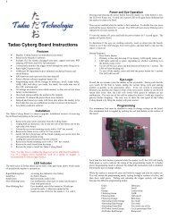
GEN 5INTIMIDATOR<strong>VICE</strong> & PROTÉGÉ <strong>MANUAL</strong> <strong>VERSION</strong> <strong>2.0</strong>BOB LONG TECHNOLOGIES209-293-4440www.boblongdirect.com
WARNINGThis paintball marker is not a toy. Misuse or mishandling can result inserious injury or death. Every person within range of a loaded paintball gunmust wear eye protection specifically designed for paintball. It isrecommended at least 18 years of age to purchase, 14 years old to usewith adult supervision or 10 years old to use on paintball fields meetingASTM standards F1777-97. Ensure you read the entire instruction manualbefore operating your marker.WARRANTY<strong>Bob</strong> <strong>Long</strong> <strong>Technologies</strong> warrants our paintball markers to be free from defect in materials and workmanship for aperiod of 1 year from purchase date. This warranty will only be honored for the initial retail purchaser and is nontransferable.Wear items such as batteries and seals are not covered under warranty. Main PCB, electropneumaticsolenoid, eye PCB’s and wire harnesses will be covered under warranty for a period of 6 Months frompurchase date.This warranty does not cover:> Any system failure resulting from the use of a non-authorized propellant. The only authorized propellants arenitrogen or compressed air.> Damage to electro-pneumatic solenoid resulting from external air source regulation failure. The use of anexternal regulated air source is your choice, so research well and choose wisely.> Damage to electro-pneumatic solenoid from foreign objects, specifically Teflon® tape.> Surface damage such as scratches, nicks, or dings.> Improper disassembly or re-assembly.> Improper lubrication. The only authorized grease for maintaining a <strong>Bob</strong> <strong>Long</strong> marker is Molykote® 55 made bythe Dow Corning Corporation (Dow 55). Authorized oil is limited to Tri-flow® or any other synthetic oil madespecifically for maintaining a paintball marker.> Modification or any other alteration of a marker or its parts. Dremels, acid, most things involving a show on theBravo network or HGTV fit in this category.> Misuse of any conceivable kind. Basically if it involves law enforcement officers, the phrase “I hope we don’t getcaught!”, use as a pry bar, or other things that would have made it into an episode of the show Jackass.This warranty is limited to repair or replacement of defective items with the initial retail purchaser to pay shippingcosts. The initial retail purchaser must enclose a copy of the original sales receipt with the marker to be repairedfor this warranty to be honored.CAUTION: READ ALL WARNINGS BEFORE USING OR ATTEMPTING ANY WORK ON YOUR <strong>VICE</strong>.SHOULD YOU BE UNSURE AT ANY POINT, STOP AND SEEK PROFESSIONAL SUPPORT.
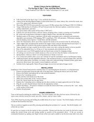
QUICK STARTINSTALLING AIR TANKMuch like any other tournament marker, the Vice requires the use of compressed air or nitrogen only. The Vice iscompatible with both high-pressure and low pressure compressed air systems. If using an adjustable-output airsystem, set the system’s output between 450 and 550 psi. Screwing your preset air system into the ASA at thebottom of the grip will pressurize the marker, preparing it for use.TURNING MARKER ON/OFFTo power on the marker: press and release the power button.To power the marker off: press and hold the power button for 1.5seconds, until the LED turns off, then release.ADJUSTING VELOCITYAlthough both of the regulators on the Vice come preset from the factory, you may need to adjust the regulatorsto account for paint to bore match, atmospheric differences, and yourfield’s maximum chronograph limit. The velocity of your marker iscontrolled through the vertical regulator, which is adjusted with a 1\8”Allen wrench. Turning the screw clockwise (or inward) will increaseyour velocity; turning the screw counterclockwise will decrease yourvelocity. Only turn the wrench 1/8 th -1/16 th of a turn with eachadjustment.TURNING EYES ON/OFFBriefly press and release the power button when the marker is turned on to disable the eyes. Briefly touch it asecond time to re-enable the eyes. Each time the marker is turned on the eyes are enabled regardless of whetherthey were enabled when the marker was shut off.For early releases of the Protégé which incorporated the Frenzy 3.0 board consult the control board manual onwww.boblongdirect.com for eye operation.CAUTION: READ ALL WARNINGS BEFORE USING OR ATTEMPTING ANY WORK ON YOUR <strong>VICE</strong>.SHOULD YOU BE UNSURE AT ANY POINT, STOP AND SEEK PROFESSIONAL SUPPORT.
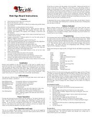
GENERATION 5 MODEL DIFFERENCES:The fifth generation Intimidator platform, including the Vice and Protégé, share the same basic operation andunderlying technology. While the Protégé provides tournament level performance in a cost effective package, theVice brings a fully loaded marker that is lighter and fully equipped. Both are designed, machined, and built in theUSA.ViceProtegeFeedneck LeverLock Twist LockControl Board Tadao Ryujin Frenzy 4.0Bolt Pillow Bolt Open Face BoltWeight Lighter Only a snackie cake differenceRam Sleeve Integrated SeparateComparison of Vice and Protégé FeaturesThe Protégé can be upgraded with the same components as the Vice, with the exception of the ram sleeve. Bothmarkers accept the Low Pressure Poppet Valve, 4C Eye System, Cam-Drive or Gear-Drive ASAs and otheraccessories. The maintenance procedures in this manual apply to both markers.MAINTENANCE SCHEDULEAmount of TimeWhile talking smack with yourfriends in between gamesEstimated Casesof paintRecommended Upkeep• Removing the bolt, and barrel• Run a swab through the firing chamber• Put a drop of oil on the bolt o-rings if your friendsare still flapping their gums• Reinstall boltAfter a day of play 1-2 Cases • Repeat above steps• Wipe down marker outside• Clean and oil boltAfter a Weekend 2-4 Cases • Repeat above steps• Remove the Ram Cap and Ram• Clean debris and old grease from ram interior• Inspect o-rings for damage• Clean and grease ramA Month 10 Cases • Repeat above steps• Clean, inspect, and grease HPR Piston o-ring6 Months or when consistencyissues appear20 Cases • Clean, inspect, and grease LPR Piston o-ring• Clean, inspect, and grease poppet shaft o-ringCAUTION: READ ALL WARNINGS BEFORE USING OR ATTEMPTING ANY WORK ON YOUR <strong>VICE</strong>.SHOULD YOU BE UNSURE AT ANY POINT, STOP AND SEEK PROFESSIONAL SUPPORT.
ADJUSTING THE TRIGGERThe Gen 5 Intimidator trigger has two adjustment screws. The bottomscrew is for trigger post-travel and the top screw adjusts the activationpoint (where the marker fires). To adjust the screws insert a hex keyand turn the screw. The screws have Loctite to prevent theadjustment from slipping so a firm, steady pressure is needed for theadjustment.REPLACING/UPGRADINGThe stock trigger is similar to the S-class trigger. However, the stocktrigger does not have a roller bearing. To replace the trigger with an S-class trigger remove the grip frame then remove the retaining screwfrom the left side of the grip frame.The trigger can be removed and a replacement inserted. Make sure toinstall the spring on the new trigger. The S-class trigger has a new pivotscrew and a spacer, which goes between the trigger and the right side ofthe grip frame. The spacer is shown in the picture below.CAUTION: READ ALL WARNINGS BEFORE USING OR ATTEMPTING ANY WORK ON YOUR <strong>VICE</strong>.SHOULD YOU BE UNSURE AT ANY POINT, STOP AND SEEK PROFESSIONAL SUPPORT.
ADJUSTING THE ASA (FRONT/BACK)The Air Source Adapter (ASA) that connects your high pressure air tank to your Vice is a direct mount ASA. Directmount ASA systems have screws that attach directly to the bottom of the grip frame. This ASA can be adjustedforward or backwards to help position the tank so that it is comfortable for you.1. Loosen the four set screws in the ASA thenlower it from the mounting studs. Notice thesmiley face integrated into the milling? Prettycool, eh?2. Adjust the mounting screw positions forwardsor backwards to achieve the position you prefer.Make sure to leave two empty holes betweeneach stud.3. Snug the studs in place. Don’t use excessiveforce. Optionally use a drop of blue Loctiteinstead to prevent them from coming loose.Additionally a drop of Loctite will help securethe four set screws in the ASA.4. A dovetail mount ASA, such as the <strong>Bob</strong> <strong>Long</strong>Cam Drive ASA, is secured by set screws whichare accessed via the inside of the grip frame.NOTE: Not all of the holes in the bottom of theframe are accessible from inside the gripframe. Use of a Dovetail mounting ASA requiresone or two 10-32 x ¼” socket set screws. Theseare not installed with the marker from thefactory but are readily available from mosthardware stores for less than $1.5. Depending on the change in the ASA positionyour macroline hose may need to be replaced.When cutting a piece of macro line make surethe cut is smooth and perpendicular to thelength of the hose. Cutting a macro line tooshort will result in a poor connection and a leakfrom the fitting. Using a tool with curved cuttingsurfaces will help ensure a solid cut as shown inthe picture.6. Install an air tank and check for any leaks withthe ASA in the new position. If it helps remindyou – change the holes, check your hose!1 23 45CAUTION: READ ALL WARNINGS BEFORE USING OR ATTEMPTING ANY WORK ON YOUR <strong>VICE</strong>.SHOULD YOU BE UNSURE AT ANY POINT, STOP AND SEEK PROFESSIONAL SUPPORT.
MAINTAINING THE EYES AND DETENTSIn the event of a chopped ball or debris in the breach, your marker eyes may need cleaning.1. Remove the eye cover screw using a 5/64” hexwrench, and remove the eye cover.2. Carefully unscrew the PCB retaining screw.(Phillips head)3. Remove the detent and spring by pressing onthe detent from inside the chamber.4. Gently tilt the eye PCB away from the body ofthe marker in order to access the inside surface.5. Use a cotton swab to clean the surface of theeye, the eye holes, detent and detent hole.Dampen the swab with rubbing alcohol ifnecessary.6. If removing the eyes from the wiring harnessunplug the harness from the eye PCB by pullingthe white plug and not the wires Pulling thewires could potentially damage your harnessand/or eye PCB.7. After the eye and detent have been sufficientlycleaned, reinstall the PCB and eye cover.1 23 45 6Optional Upgrade: The use of 4C eyes allows thecontrol board to calculate when the paintball will befully in the breach based on the drop rate into thechamber. This results in quicker firing once the ball isin the chamber. The 4C eyes are installed in thepicture to the right with the stock eyes sitting next tothem.Optional Upgrade: The standard Delrin detents canbe replaced with Super Ds - an upgraded Type IIIanodized aluminum detent which provides longerdetent life. If the Super Ds are used the sides of thedetents must be greased slightly. Super Ds must berotated slightly each time the eyes are cleaned inorder to ensure even wear.CAUTION: READ ALL WARNINGS BEFORE USING OR ATTEMPTING ANY WORK ON YOUR <strong>VICE</strong>.SHOULD YOU BE UNSURE AT ANY POINT, STOP AND SEEK PROFESSIONAL SUPPORT.
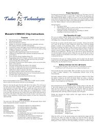
MAINTAINING THE HPRYour Vice comes equipped with the best regulators on the market. To ensure the best consistency and the highestflow possible, it is recommended that you clean and grease the in line regulator (HPR) according to themaintenance schedule.1. Degas the marker and ensure that there are nopaintballs in the breech or barrel of the marker.2. Remove your macroline hose from the 90˚fitting on your regulator. Push up on the hosethen hold the silver ring while pulling the hosedown.3. Unscrew the regulator from the verticaladaptor, and set your marker down.4. Grasp the two halves of the regulator, andunscrew the regulator base counter clockwise.5. Reach into the regulator base with tweezers orneedle nose pliers to remove the regulatorpiston.6. The main valve does not need to be removedfrom the upper portion of the regulator. Neverreplace or attempt to service a working mainvalve.7. Inspect the surface of the piston and piston o-ring for excessive wear or nicks, and replace asnecessary.8. Inspect the interior walls of the regulator base—if necessary, use a swab on the interior of theregulator base to clean debris and old grease.9. When reassembling the spring follower (springstack assembly) make sure that the top andbottom spring washers curve to the outside. Aclose up of the spring assembly with theretaining o-ring is shown to the right. Theretaining o-ring does not require lubricationIf in doubt – just stack the spring washers likethis:)()()()(10. Grease the piston o-ring with and gently replacethe spring follower (spring stack assembly) andpiston into the regulator base. There is aconcave area around the o-ring that holdsadditional lube and reduces the need forfrequent maintenance. Reassemble theregulator to the marker. Make sure theregulator body halves and the regulator itselfare snugly screwed together.1 23 45 67 89 10CAUTION: READ ALL WARNINGS BEFORE USING OR ATTEMPTING ANY WORK ON YOUR <strong>VICE</strong>.SHOULD YOU BE UNSURE AT ANY POINT, STOP AND SEEK PROFESSIONAL SUPPORT.
SETTING HPR PRESSUREThe HPR pressure is adjusted through a hex screw at the bottom of theregulator. Turning the screw clockwise increases the pressure and velocity.Turning it counterclockwise will lower the pressure and velocity. Only turn thewrench 1/8 th -1/16 th of a turn with each adjustment.After rebuilding the regulator you can do a basic setting using a second ASA witha gauge installed in the place of a macro fitting. For this method unscrew theHPR from the marker then screw on the second ASA to the top of the regulator.Once an air source is connected you can see the pressure leaving the regulator. A basic setting of 200 PSI issufficient for initial tuning of the marker. ALWAYS TEST YOUR VELOCITY WITH A CHRONOGRAPH AFTERADJUSTING YOUR HPR.SETTING LPR PRESSURE1. Remove the bolt from the marker.2. Remove the back cap and tap the ram out into thepalm of your hand.3. Screw the tester into the marker body – it uses the amcap threads.4. Attach the air source and, if necessary, turn on theASA.5. Turn on the marker’s control board and disable theeyes.6. If you did everything correctly you will now see the pressure your LPR is set to. This justifies cookies.7. Adjust the LPR using small increments – 1/8 of a turn at a time. Keep pulling the trigger while doing theadjustment to allow pressure to equalize. Maniacal laughter during this step is optional, but highlyencouraged.8. The stock poppet should have the LPR between 70-75psi. The upgraded Low Pressure Poppet Valveshould be 65-70 psi. Once the pressure is set correctly:• Turn off the board• Degas the marker• Remove the tester and reassemble the ram, back cap, and boltIf you are still laughing maniacally at this point it is getting creepy. Take a break from laughing and getsome cookies.
MAINTAINING THE LPR1. Remove the macro-line and the HPR fromyour marker. Set the regulator to the side.2. Remove the LPR retaining screw from insidethe vertical adaptor.3. Slide the LPR assembly forward and out ofthe marker4. Remove the adjustment screw from the endof the LPR then remove the LPR cap.5. Tap the LPR body on a hard, flat surface toallow the LPR piston, spring, and springfollower to slide out of the regulator base.If the piston doesn’t come out easily someneedle nose pliers will make pulling it outeasier. Gently grab the nubbin on the endto pull it out.6. Inspect the surface of the piston and o-ringfor excessive wear or nicks. Wipe off theold grease and replace the o-ring ifnecessary. Note that the nubbinmentioned in the previous step is at thebottom in the above picture. Our mainengineer hates it when we call it the nubbinbut we may get this paragraph throughreview before he catches it.7. Use a swab to clean the interior of the LPRbody. Don’t try to remove the main valve inthe center. Use caution to avoid gettingfibers stuck to the main valve when usingthe swab.8. Lubricate the piston o-ring with grease.There is a concave area around the o-ringthat holds additional lube and reduces theneed for frequent maintenance. Gentlyreplace the piston, spring, and springfollower (washer) back into the LPR body.9. Tightly screw the LPR cap to the LPR body.Put a drop of blue Loctite on theadjustment screw threads. To completereassembly reverse the steps you usedwhen disassembling the LPR.1 23 4567 8CAUTION: READ ALL WARNINGS BEFORE USING OR ATTEMPTING ANY WORK ON YOUR <strong>VICE</strong>.SHOULD YOU BE UNSURE AT ANY POINT, STOP AND SEEK PROFESSIONAL SUPPORT.
MAINTAINING THE POPPET VALVE ASSEMBLY1. With the LPR removed from the marker,remove the poppet valve by tapping thefront of the marker firmly against the palmof your hand or a padded surface.Alternately use a pair of needle nose pliers,remove the poppet return spring andpoppet valve from the front of the ramsleeve.2. If step #1 sounds annoying do it the easierway – remove the ram as described in theram maintenance instructions and use achopstick to push the poppet out from theback. (If you don’t have a chopstickordering Pad Thai for lunch will get you achopstick)3. Inspect the surface of the poppet and o-ringfor excessive wear or nicks, and replace asnecessary.4. Clean debris and excess grease from thepoppet surface, and grease the poppet o-ring.5. Replace the poppet and poppet returnspring into the ram sleeve, and attach theLPR with the LPR retaining screw. Thenarrow end of the tapered spring goestowards the poppet with the wider endgoing toward the LPR.NOTE: If you aren’t sure whether you have theregular or LP poppet take a look at the shaft.The LP poppet has a silver shaft.CAUTION: READ ALL WARNINGS BEFORE USING OR ATTEMPTING ANY WORK ON YOUR <strong>VICE</strong>.SHOULD YOU BE UNSURE AT ANY POINT, STOP AND SEEK PROFESSIONAL SUPPORT.
MAINTAINING THE BOLT1. De-gas the marker and insure that there are no paintballs inthe breech or barrel of the marker.2. Remove the bolt from the marker by pulling upward on thepull pin.3. Slide the bolt to the rear of the marker body.4. Inspect the surface of the bolt and o-rings for excessivewear or nicks, and replace as necessary.5. Place one drop of oil on each o-ring and spread it aroundthe ring with your finger to ensure an equal coating.6. Inspect the firing chamber and body – if necessary run aclean swab through the body to clean out any dust or debris.7. Reinsert the bolt into the marker ensuring to place the pin into the groove of the ram.MAINTAINING THE RAM1. Remove the bolt from the marker2. Remove the back cap from the marker3. Tap the ram out into the palm of your hand – if you havetrouble tapping it out use a hex key or chopstick to push itback from the top where the bolt sits.4. Wipe off any old grease or debris.5. Wipe out any old grease from the ram housing using aswab.6. Inspect the o-rings for excessive wear or nicks, and replaceas necessary.7. Apply a thin coat of grease to the o-rings.8. Reinsert the ram with the smaller diameter section to thefront of the marker.9. Replace the back cap and tighten snugly.10. Perform the Bolt maintenance process.
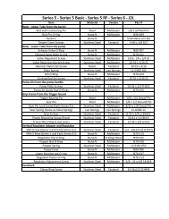
O-RINGS AND FASTENERSO-RINGSPart Name Specifications QuantityDrive Manifold O-rings 1mm X 3mm Buna (Durometer 70) 290 Degree Hose Barb Fitting Seal 1mm X 3mm Buna (Durometer 70) 1Solenoid Manifold O-ring 1mm X 4.5 mm Buna (Durometer 70) 1Ram Cap (Vice – located on Ram Cap) 1mm X 12mm Buna (Durometer 70) 1Ram Cap (Protégé-located in Ram Sleeve) 1mm X 14mm Buna (Durometer 70) 1Poppet Shaft O-ring 006 Buna (Durometer 70) 1Front Ram O-ring 006 Buna (Durometer 70) 1Rear Ram O-ring 011 Buna (Durometer 70) 1LPR Piston O-ring 012 Buna (Durometer 70) 1Bolt O-rings 015 Buna (Durometer 70) 3360˚ Regulator ASA Adapter Internal O- 014 Buna (Durometer 70) 2Rings360˚ Regulator ASA O-ring 015 Buna (Durometer 70) 1Poppet Housing (Vice) 015 Buna (Durometer 70) 3Ram Sleeve (Protégé) 015 Buna (Durometer 70) 5LPR Housing O-rings 015 Buna (Durometer 70) 3360˚ Inline Regulator Piston O-ring 016 Buna (Durometer 70) 1Primary Air Chamber Gasket 028 Buna (Durometer 70) 1CAUTION: READ ALL WARNINGS BEFORE USING OR ATTEMPTING ANY WORK ON YOUR <strong>VICE</strong>.SHOULD YOU BE UNSURE AT ANY POINT, STOP AND SEEK PROFESSIONAL SUPPORT.
FASTENERSPart Name Specifications QuantityBottom PCB Retaining Screw M2x4mm Pan Head Machine Screw 1Top PCB to Grip Frame M2x12mm Pan Head Machine Screw 2Bottom Air Passage Plug M3x3mm Cup-Point Socket Set Screw 1Rear Air Passage Plug (Vice) M3x5mm Cup-Point Socket Set Screw 1Front Air Passage Plug (Vice) M3x5mm Cup-Point Socket Set Screw 1Rear Air Passage Plug (Protégé) M3x8mm Cup-Point Socket Set Screw 1Front Air Passage Plug (Protégé) M3x8mm Cup-Point Socket Set Screw 1Eye Cover Screws 2-56x1\4” Socket Head Cap Screw 2Eye PCB Retaining Screws 2-56x1\4” Flat Head Machine Screw 2Drive Manifold Screw 2-56x1\4” Socket Head Cap Screw 1Trigger Activation Point Set Screw 6-32x3\8 Cup-Point Socket Set Screw 1Trigger Post-Travel Set Screw 6-32x1\4 Cup-Point Socket Set Screw 1Grip Panel Screws 6-32 x 3\16 Button Head Socket Cap Screw 6Xpress Mount ASA Set Screws 8-32x3\16 Cup Point Socket Set Screw 4Rear Grip Frame Screw 10-32x5\16 Button Head Socket Cap Screw 1LPR Retaining Screw 10\32 x 1\2 Socket Head Cap Screw 1360˚ HPR Swivel Lock Screws 10\32x1\4” Cup-Point Socket Set Screw 2360˚ HPR Adjustment Screw 1\4-28x3\8 Cup-Point Socket Set Screw 1CAUTION: READ ALL WARNINGS BEFORE USING OR ATTEMPTING ANY WORK ON YOUR <strong>VICE</strong>.SHOULD YOU BE UNSURE AT ANY POINT, STOP AND SEEK PROFESSIONAL SUPPORT.
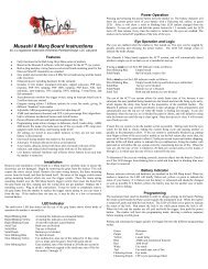
O-Ring Size Table1x3mm1x4.5mm1x12mm1x14mm006 011012 014015 016028CAUTION: READ ALL WARNINGS BEFORE USING OR ATTEMPTING ANY WORK ON YOUR <strong>VICE</strong>.SHOULD YOU BE UNSURE AT ANY POINT, STOP AND SEEK PROFESSIONAL SUPPORT.
Q&A1. Q: My Vice is VERY bouncy and I can’t do anything! I’ve topped out the debounce and AMB and I put thetrigger in like every position possible. Would it be the loader delay help any? What else should I do?A: Make sure the trigger spring is installed. Make sure the trigger activates near the end of the pull. Ifnecessary back out the trigger activation set screw ½ turn.2. Q: Where can I get an o-ring kit?A: <strong>Bob</strong> <strong>Long</strong> <strong>Technologies</strong> and authorized resellers have o-ring and parts kits available.3. Q: What is the recommended dwell setting?A: Dwell should be at 6 when you get the marker and after you use it. There's no advantage to running ahigher dwell to "break it in". There are exactly zero heavy springs in the HPR or LPR that need broken in.4. Q: What pressure should my LPR be set to with the LPR tester?A: The Upgraded Low Pressure Poppet around 65-70. The stock poppet should enable you to run the LPRaround 70-75.5. Q: I am seeing large velocity fluctuations – what should I do?A: Check for a good paint to barrel match. Ensure the HPR shim stack is assembled correctly and that yourram, LPR, HPR and poppet o-rings are lubed with Dow 55. Check the LPR pressure and apply a drop ofblue Loctite to the threads of the LPR adjustment screw.6. Q: I lowered my bolt delay and now the eyes registering an eye malfunction and lowered my bps to 12.What should I do?A: The bolt delay is too low at 8ms, the eyes are activating too early while the bolt is still cyclingbackwards to prepare itself for the next paintball to drop. The eyes activate, see your bolt, and neverregister a change from the bolt to the ball coming in place. Raising the setting to 10 will normally clearthis problem.7. Q: So what is this bolt delay setting?A: Bolt delay is actually an eye activation setting and not a bolt setting. Essentially you need a delay addedin so the eyes don't turn on as the bolt is on it's backward travel. If they turn on too soon, the markerthinks the bolt is a ball and will queue up the next shot. This causes skipped shots and often chops. Keep itat 10 (or higher)...because your board isn't seeing a gap between when the bolt cycles and the ball dropsand thinks the eyes are malfunctioning.8. Q: What weight is the stock vice micro switch?A: 80g9. Q: How much oil should I put on the bolt?A: Just a drop on each o-ring. Put a drop on, then use your finger to put it around the entire ring. Toomuch oil can cause bolt movement problems or result on oil splattering on the eye system in extremecases.10. Q: What threading is the barrel?A: AutocockerCAUTION: READ ALL WARNINGS BEFORE USING OR ATTEMPTING ANY WORK ON YOUR <strong>VICE</strong>.SHOULD YOU BE UNSURE AT ANY POINT, STOP AND SEEK PROFESSIONAL SUPPORT.
11. Q: Should my air hose be squeezed between the solenoid and frame like in the picture below?A: This is normal and does not impact air flow.12. Q: Is the Stock trigger a roller bearing?A: Nope13. Q: What items are recommended to keep in my toolkit?A: Each of the following:• LPR tester• Dow 55• Triflow oil• O-rings• Timmy hose for solenoid• One wooden chopstick (occasionally helpful for poppet or ram removal)• Hex key set14. Q: How do I reset the settings to factory on the Ryujin board?A: Hold the tourny lock for 10sec15. Q: My HPR seems to keep coming loose – what should I do?A: Degas your marker. Take off your regulator and take out both set screws, Separate the threads of theHPR from the HPR body. You'll know where your set screws are holding, you'll see the little indents theymake around there. Wipe off lube well, and if there's some excess on the screws, do that too. Put it backtogether and crank down with moderate pressure. If you're throwing your whole body into it and it's stillnot holding, there's too much lube left still.16. Q: My feedneck isn’t tightly clamping my loader- what should I do?A: For the Vice – use a hex wrench to tighten the adjustment screw.17. Q: I can’t seem to get an adjustment screw on my trigger to move – what should I do?A: Most triggers have blue Loctite on the adjustment screw. Just apply some steady force with the hexwrench and the screw will move.CAUTION: READ ALL WARNINGS BEFORE USING OR ATTEMPTING ANY WORK ON YOUR <strong>VICE</strong>.SHOULD YOU BE UNSURE AT ANY POINT, STOP AND SEEK PROFESSIONAL SUPPORT.
18. Q: What is the racetrack o-ring?A: It is the o-ring in the body of the marker above the grip frame. It is actually a round o-ring just sitting inthe oval groove. If you have leaking between the body and grip frame remove o-ring, lubricate and placeback into the slot.19. Q: Where can I find additional information and other users of <strong>Bob</strong> <strong>Long</strong> Markers?A: www.intimidatorowners.com also the PBNation subforums dedicated to <strong>Bob</strong> <strong>Long</strong> products located athttp://www.pbnation.com/forumdisplay.php?f=14620. Q: I need to ship my marker in for technical support – what is the address?A: The address varies depending on whether shipping by postal service or another method.USPS/Postal Shipping:<strong>Bob</strong> <strong>Long</strong> <strong>Technologies</strong>P.O. Box 457Mokelumne Hill, CA 95245Other shipping methods:<strong>Bob</strong> <strong>Long</strong> <strong>Technologies</strong>11669 Highway 26Mokelumne Hill, CA 9524521. Q: Where can I order a jersey like on the cover of the manual? www.intimidatorowners.comCAUTION: READ ALL WARNINGS BEFORE USING OR ATTEMPTING ANY WORK ON YOUR <strong>VICE</strong>.SHOULD YOU BE UNSURE AT ANY POINT, STOP AND SEEK PROFESSIONAL SUPPORT.
TROUBLESHOOTING GUIDEMarker will not turn on out of the boxVelocity is inconsistent over the chronographMarker is breaking paintMarker does not gas up after tank isconnectedMarker does not display correct LED indicatorcolor when turned onMarker is leaking from the ASAMarker is leaking from the HPRAir is leaking from the front of the markerframe-Ensure that the battery that you’re using in your new marker is ahigh quality alkaline 9 volt.-Verify that your battery is correctly oriented (matching with thecorrect terminals), and that it is making firm contact with theprongs on the circuit board.-Make sure that the wiring harness is correctly inserted into thereceptacle, and that the on\off pad is making contact with theswitch on the circuit board.-Always check that your paintballs are of high quality, andconsistent in size, as well as using a good paint to bore match.-Make sure the LPR and the HPR are set to the proper pressures.-Replace your battery.-Inspect the ram o-rings for nicks and that they are properlygreased- Always check that your paintballs are of high quality, andconsistent in size, as well as using a good paint to bore match.-Make sure the LPR and the HPR are set to the proper pressures.-Ensure that your detents and bolt face are in good condition, andthere is no debris in the breech of the marker.-Reset your board settings to factory settings and use a force-fedloader.-Check the tension/pressure settings if you are using a force fedloader. Having too high of a feed pressure with fragile paint cancause balls in the stack to break-Verify that the pin valve on your tank is outputting pressure tothe regulator—some tanks will not work properly with certainASAs.-Attempt gassing up the marker with another tank to see if thisremedies the issue.-Verify that your battery is correctly oriented (matching with thecorrect terminals), and that it is making firm contact with theprongs on the circuit board.-Verify that the breech of the maker is clear of obstructions, thebolt is in the back position, and that the eyes are clean andplugged into the harness.-Check the tank o-ring (015 Urethane D90) for nicks or tears.-Check that the macroline hose is in good condition and is cutevenly- The macroline fitting has a 010 o-ring. Remove the fitting andreplace the o-ring if the above does not correct the problem-If the leak is coming from the macroline elbow, make sure thatthe macroline fitting has been secured to the regulator withfactory approved thread-sealant (NOT TEFLON TAPE)- Check that the macroline hose is in good condition and is cutevenly-Replace the piston o-ring inside the regulator.-Verify that the racetrack o-ring in the front of the frame is free ofnicks and has a light coat of grease to induce swelling.-Verify that the screw in the center of the vertical ASA is snug andthat nothing obstructing the frame from making a tight seal withthe bottom of the body.CAUTION: READ ALL WARNINGS BEFORE USING OR ATTEMPTING ANY WORK ON YOUR <strong>VICE</strong>.SHOULD YOU BE UNSURE AT ANY POINT, STOP AND SEEK PROFESSIONAL SUPPORT.
Air is leaking from the rear of the markerframeMarker leaks down the barrelMarker fires more than one shot per pull, orhas trigger bounceMarker double feeds-Remove the trigger frame from the marker, and inspect the hoseto the solenoid. If it appears worn or pinched, consider replacingthe hose.-If your marker has this excessive compression of the hosereplace the hose and apply a small amount of grease to the hoseto allow it to compress in the frame without being deformed. Ifthis does not fix your issue, consult expert advice or seekprofessional repair-Ensure that your ram o-rings are free of nicks, and properlylubricated.-Verify that your poppet seal is in good condition, with its shaft o-ring is free of nicks and properly lubricated.-If this does not correct your issue, consult expert advice or seekprofessional repair- Verify that your trigger has the spring installed and that it isproperly seated- Verify that your marker is in semi-automatic mode- Raise your marker’s debounce level, and make sure that yourtrigger activation level is not too short.-Verify that detent springs are in place and detents move freely-Replace the marker’s ball detents if they are excessively worn-If using Super Ds make sure the detents are lubricated on thesidesCAUTION: READ ALL WARNINGS BEFORE USING OR ATTEMPTING ANY WORK ON YOUR <strong>VICE</strong>.SHOULD YOU BE UNSURE AT ANY POINT, STOP AND SEEK PROFESSIONAL SUPPORT.