Wheel of Fortune Pusher
Wheel of Fortune Pusher
Wheel of Fortune Pusher
- No tags were found...

You also want an ePaper? Increase the reach of your titles
YUMPU automatically turns print PDFs into web optimized ePapers that Google loves.
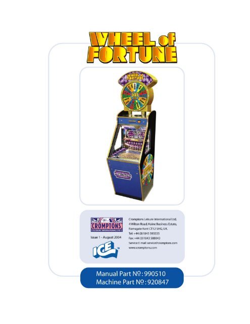
1 PLAYER WHEEL OF FORTUNEOPERATOR’S MANUALMachine Part Number: 920847Manual Part Number: 990510 Issue 1© 2004 Cromptons Leisure International LtdAll Rights ReservedNo part <strong>of</strong> this publication may be reproduced in any form without thewritten permission <strong>of</strong> Cromptons Leisure International Limited.Every effort has been made to ensure that the information contained inthis manual is accurate. Cromptons Leisure International Limited reserve theright to make alterations without prior notice.Cromptons Leisure International Limited4 Wilton Road, Haine Industrial Estate, Ramsgate, KentCT12 5HG. UKTel: +44 1843 593335 Fax: +44 1843 588043 www.cromptons.com920847 <strong>Wheel</strong> Of <strong>Fortune</strong> 2
List <strong>of</strong> Contents1. Introduction1.1 Warnings, Cautions and Notes 51.2 Safety Precautions 51.3 Abbreviations and Terms 52. Game play & Description2.1 Game play & Description 62.2 Game play 72.3 Navigation Front 82.4 Navigation Back 92.5 Navigation Top Sign 103. Installation & Setup3.1 Installation 113.2 Setting-up the Playfield with Coins 113.3 Pre-Operation Checks 114. Security4.1 Tilt Bob 124.2 Intelligent Tilt 134.2 Slam Tilt 135. Programmer & Dipswitch Settings5.1 Sound PCB & Dip Switch Settings 145.2 Main Control PCB - General 155.3 Main Control PCB – Dipswitch 155.4 Main Control PCB – Dipswitch SW1 165.5 Main Control PCB – Dipswitch SW2 166. Ticket Refill6.1 Refill Ticket Routine 177. Routine Maintenance167.1 Daily Inspection 187.a PSU Rack Checks 197.b Fluorescent Lamp replacement 207.c Coin Entry Check 217.d Playfield 217.e Pin Perspex Removal 227.f Back Door Removal 237.g Payout Level 247.h Lock Replacement 258. Electrical Wiring Schematic 269. Parts List 27920847 <strong>Wheel</strong> Of <strong>Fortune</strong> 3
1. IT IS ESSENTIAL THAT ONLY SUITABLY QUALIFIEDPERSONNEL CARRY OUT MAINTENANCE AND REPAIROPERATIONS.2. TO PREVENT INJURY AND ELECTRIC SHOCK, SWITCH OFFAND DISCONNECT ALL ELECTRICAL POWER SUPPLIESBEFORE OPENING DOORS AND PANELS AND STARTINGWORK ON THE MACHINE.3. TO PREVENT ELECTRIC SHOCK DURING OPERATION, ASECURE, GROUNDED ELECTRICAL PLUG MUST BE FITTED.4. USE ONLY THE SPECIFIED ELECTRICAL FUSES SHOWN INTHE PARTS LIST. REPLACEMENT FUSES MUST MATCHTHOSE TO BE REPLACED IN FUSE TYPE AND RATING. THEFUSE COVER (WHERE APPLICABLE) MUST BE IN PLACEBEFORE SWITCHING THE MACHINE ON.5. TO MAINTAIN THE SAFE AND EFFICIENT OPERATION OFTHE MACHINE, USE ONLY PARTS THAT HAVE BEENSUPPLIED BY CROMPTONS, OR ARE CROMPTONSAPPROVED.6. THIS MACHINE IS INTENDED FOR INDOOR USE ONLY.CAUTION1. MANY ELECTRICAL PLUGS ARE KEYED TO FIT ONE WAY.NOTE ORIENTATION BEFORE REMOVAL.2. BEFORE HANDLING A PCB OR ITS COMPONENT PARTS,TAKE FULL ANTI-STATIC PRECAUTIONS.3. WAIT FOR AT LEAST ONE MINUTE AFTER SWITCHING THEMACHINE OFF, TO ENABLE THE CAPACITORS TO FULLYDISCHARGE BEFORE SWITCHING BACK ON. FAILURE TODO SO MAY RESULT IN A LOSS OF FUNCTIONALITY.920847 <strong>Wheel</strong> Of <strong>Fortune</strong> 4
IntroductionThis manual is intended to act as a guide to the operation <strong>of</strong> the machine.The list <strong>of</strong> contents shows the layout <strong>of</strong> the manual. Should repairs benecessary, there is a Parts List <strong>of</strong> components that are normallyconsidered replaceable. Recommendations are made throughout themanual and it is essential that these be followed for safety reasons.1.1 Warnings, Cautions and Notes“WARNING”: refers to essential safety precautions that must be taken to avoida potential hazard to health.“CAUTION”: refers to precautions that must be taken to avoid damage to theequipment.“NOTE”: refers to advisory information, normally to assist in performingtasks.1.2 SAFETY PRECAUTIONSThe following general Safety Precautions apply to all Operators and Engineersand must be complied with at all times. More specific warnings and cautionsare also provided in the manual where they apply.1.3 Abbreviations and TermsUnits used are the standard SI units, e.g. grams “g”, volts “V”, etcAbbreviationsAssy. AssemblyCW ClockwiseDIP Dual In-line PackageEMC Electro Magnetic Compatibility.GRP Glass Reinforced Plastic.ICE Innovative Concepts in EntertainmentJST Japanned Solderless TerminalLED Light Emitting Diode.PCB Printed circuit board.PSU Power supply unit.TBD To be done.LH Left HandRH Right HandTermsCoin Coin or TokenFixings Small pieces <strong>of</strong> metalwork, etc used for assemblySlug Counterfeit coin or token920847 <strong>Wheel</strong> Of <strong>Fortune</strong> 5
2.0 GAME PLAY & DESCRIPTIONMarquee LevelCoin Entry LevelPlayfield LevelPayout LevelFigure 1- General View <strong>of</strong> <strong>Wheel</strong> <strong>of</strong> <strong>Fortune</strong>2.1 General DescriptionThe <strong>Wheel</strong> <strong>of</strong> <strong>Fortune</strong> can be divided into 4 separate levels as shown in Figure 1Each level contains assembly <strong>of</strong> components that at times may requireadjustments and maintenance.920847 <strong>Wheel</strong> Of <strong>Fortune</strong> 6
2.2GAME PLAY4When all 14 lettersare lit the bonus wheelspins for extra tickets1Drop Quarter or Tokendown the Skill Arm.2Use the Button to stopthe arm and direct the coin.Time the drop with the runninglights.5The Quarter or Tokencontinues to the playfield andpushes coins forward towards3 Each time a running light ishit a WHEEL OF FORTUNE letteris lit.6 When coins fall over the edge,tickets are paid to the player.920847 <strong>Wheel</strong> Of <strong>Fortune</strong> 7
Marquee AssemblySkill Stop ButtonCoin Entry DoorPin Perspex AssyTicket PayoutLatch Switch<strong>Pusher</strong> Box AssyMain Control BoardEdge Win Count Module920847 <strong>Wheel</strong> Of <strong>Fortune</strong> 8
Motor Drive Arm AssyLED Bonus BoardMotor Interlock SwitchPSU Rack AssyLED Bonus BoardPower SupplyHalogen TransformerMains Power Filter920847 <strong>Wheel</strong> Of <strong>Fortune</strong> 9
Stepper Motor& Fan AssyLED Lighting PCB<strong>Wheel</strong> PerspexLED Controller& Stepper DriveCardTopSign Glitter CoatHousingLED Lighting PCB920847 <strong>Wheel</strong> Of <strong>Fortune</strong> 10
Installation & Setup3.1 Installationi. Remove the machine from the shipping crate and check that it is complete.Any special instructions and the entry keys are attached to the outer surface <strong>of</strong>the machine. Ensure that all transit packing is removed from outside and insidethe machine. Close and lock all doors and panels.ii.iii.iv.The machine must be installed for use on a stable, level surface. It must not beexposed to extremes <strong>of</strong> temperature or high humidity. Ensure that the mainselectrical supply is grounded and complies with the specification shown on theIdentification Label (normally located on the side <strong>of</strong> the machine). Ensure theswitch on the electrical socket is set to "ON". Connect to the mains electricalsupply using a readily accessible disconnect device, and switch on the supply,starting the machine. The power switch is located in the payout level <strong>of</strong> themachine, (see page 19)Check that all lights are working and that the pusher box is moving smoothly.When the machine appears to be functioning correctly, set up the playfields asfollows.Check that the skill arm is working correctly (see page 7, Game Play)3.2 Setting-Up the Playfield with CoinsThe following set-up procedure is recommended before the machine is played:-i. To "float-up" the play area, turn the machine on, open the glass access doorand spread approximately 720 coins evenly over the Playfield.ii. To settle the machine ready for play, feed approximately another 720 coinsevenly onto the playfield through the Coin Entry.iii. Open the Payout door and fill the Ticket Dispenser.3.3 Pre-Operation Checksi. Visually check that the playfield is correctly set up with Coins.ii. Open the Payout Door and visually check the and Ticket Dispenser is full.iii. Set the Sound Volume to the desired level (Figures 3).iv. Feed several Coins into the Coin Slot and visually check that the Coins fallonto the Playfield correctly.v. Check that the Coin Entry sound is triggered each time a Coin is entered.vi. Check the operation <strong>of</strong> the skill stop arm by pressing the button to stop thearm.CAUTION:DO NOT FILL THE COUNTHOPPER WITH COINS AS THEMACHINE WILL PAYOUTINCORRECTLY920847 <strong>Wheel</strong> Of <strong>Fortune</strong> 11
4.0 SecurityThe machine uses three separate tilt mechanisms to enhance security:The Alarm is a continuous two tone sound that lasts for approximately 8-10seconds.The machine is protected by three different tilt mechanisms - the Tilt Bob, theSlam Tilt and the Intelligent Tilt. The settings <strong>of</strong> each can be adjusted to altertheir sensitivity.Please note that these settings are critical to ensure game play – they must be setsensitively enough to protect the machine, but if they are set too sensitively, gameplay will be adversely affected.4.1 TILT BOB MECHANISM ADJUSTMENT.The Tilt Bob is housed in the coin entry level<strong>of</strong> the machine.It operates under gravity by making contactbetween the metal frame and the freeswingingbob if the machine is tilted beyond apre-determined angle.To set the tilt angle, loosen the LockingScrew on the side <strong>of</strong> the bob. The bob canthen be moved up the shaft to increase theoperating angle or down the shaft to decreasethe angle. Ensure that the Locking Screw istightened following adjustment.Tilt Bob Mechanism920847 <strong>Wheel</strong> Of <strong>Fortune</strong> 12
4.2 INTELLIGENT TILTADJUSTMENTThe piezo-electric sensors and associated PCBs are secured to the underside <strong>of</strong> theWin Chutes.The sensitivity <strong>of</strong> the Intelligent Tilt mechanism can be adjusted by turning thepotentiometer VR1 on the Intelligent Tilt PCB.Turning the potentiometer anti-clockwise increases sensitivity, and turning itclockwise decreases sensitivity.To test for correct function:1. Remove the Glass Door from the Play Section.Intelligent Tilt Assembly2. Position a coin at the edge <strong>of</strong> the Playfield, as far away from the Coin FallDetector as possible (to check for maximum sensitivity).3. Gently push the coin over the edge so that it drops into the win chute, as itwould do in normal play.4. As the coin enters the win chute, visually check that the LED on the PCBlights, indicating that the coin has been detected. This will not cause the alarmto sound.If the LED does not light, turn the potentiometer anti-clockwise slightly and repeatthe test.4.3 SLAM TILT ADJUSTMENTThe Slam Tilt Switches comprise anadjustable switch with a weight mounted ona sprung arm.The switch operates if the machine is struckwith enough force to move the weight andclose the electrical contactsTightening the Adjusting Screw reduces thegap between the contacts and makes theswitch more sensitive920847 <strong>Wheel</strong> Of <strong>Fortune</strong> 13
5.0 Programmer & Dipswitch Settings5.1 SOUND PCB – DIPSWITCH SETTINGSA Dipswitch unit mounted on the SoundPCB is used to control the “Attract Sound”.This sound is intended to attract players tothe machine when it is not being played).The time interval between the sounds issettable as shown below. Only switches 1 to3 <strong>of</strong> the 8 switches are currently used.Sound CardSW1 SW2 SW3 Time IntervalOFF OFF OFF No attract soundON OFF OFF 30 SecondsOFF ON OFF 60 SecondsON ON OFF 90 SecondsOFF OFF ON 120 SecondsON OFF ON 150 SecondsOFF ON ON 180 SecondsON ON ON 210 SecondsTable 1 "Attract Sound" - Dipswitch Settings920847 <strong>Wheel</strong> Of <strong>Fortune</strong> 14
5.2 MAIN CONTROL PCB –GENERALA separate Main Control PCB is used tocontrol each play section. Above eachPCB is a label with its Play Sectionnumber.Each PCB has two LEDs incorporated:LED1 is illuminated while there is powerto the PCB.LED2 is a s<strong>of</strong>tware monitor that flashesregularly while the program is runningcorrectly. If this LED stops flashing atany time, pressing the Reset Button willcause the program to be reset.Figure 2 - Control PCBPressing the Reset Button resets the control system for that Play Section withoutdisturbing other parts <strong>of</strong> the machine. Pressing this button will also cause unpaidtickets to be paid out following a refill.5.3 Main Control PCB - Dipswitch SettingsTwo banks <strong>of</strong> Dipswitches are located on each Main Control PCB, labelled“SW1” and “SW2” (Figure 5). The switches themselves are labelled with thenumbers “1-8” and the ‘ON’ position is shown.The Dipswitch settings take effect only at Power-up or after the Main ControlPCB Reset button has been pressed.A S<strong>of</strong>tware Specification Sheet is located inside the ticket level <strong>of</strong> each machine.This specifies the Dipswitch settings for that particular machine and, in the event<strong>of</strong> conflicting information, should be followed in preference to the settings shownbelow.920847 <strong>Wheel</strong> Of <strong>Fortune</strong> 15
5.3 - Dipswitch SW1DS Default Setting DescriptionMerci TicketAdjustment1 +1 ON2 +2 OFF3 +4 OFFIf all OFF no Merci Ticket is paid.DS1 ON = 1 TicketDS1 & 2 ON = 3 Tickets (cumulativevalues)Number <strong>of</strong>Tickets paidper coin overthe edge4 +1 ON5 +2 OFF6 +4 ON7 +8 OFFIf all OFF no Tickets paidDS1 & 6 ON = 5 Tickets paid for eachcoin over the edge (cumulative values)Not Used 8 OFF Not Used5.4 - Dipswitch SW2DS Default Setting DescriptionFeature TicketAdjustment9 +1 OFF10 +2 OFF11 +4 ONAve tickets from feature per coin inDS11 ON = Ave 4 tickets per coin in.12 - OFF Clear Down RAM settingsTEST Modes13 - OFF14 - OFF15 - OFF16 - OFFOnly used for Test modes pleasecontact your DistributorThe above default setting will give the following payout:For every coin in deliver 1 merci ticket, 5 tickets for every coin over the edgeand average 4 tickets for the <strong>Wheel</strong> <strong>of</strong> <strong>Fortune</strong> bonus payout. Effectively thiswill total 10 tickets out for every coin in.920847 <strong>Wheel</strong> Of <strong>Fortune</strong> 16
Tickets Reload Sequence6.0 Filling Ticket Dispenser VersionsAn LED visible on the playfield also indicates when Tickets are low. When asection runs out <strong>of</strong> tickets, an audio alarm indicates “Tickets Empty.”To refill ticket bin and pay out any remaining tickets, carry out the followingstepsi. Remove the Payout Door. Place the block <strong>of</strong> folded tickets in the TicketBox so that the feed will be in correct orientation.ii.iii.Switch the power supply ON (if not already on) and press the advancebutton on the side <strong>of</strong> the dispenser until tickets appear at the Payout Slot.Tear <strong>of</strong>f any excess tickets and replace the Payout Door. Take care not totrap the tickets.iv. The machine verifies tickets are present and pays any tickets owing andallows the game to be continued.v. The door switch (see Navigate-Front, page 8) has a pull latch ON state fortesting ticket payout with the door open.Ticket Low LED920847 <strong>Wheel</strong> Of <strong>Fortune</strong> 17
7.0. Routine MaintenanceDaily InspectionIt is recommended that the following checks are carried out daily:i. Switch the machine on.ii. Visually check that the machine is clean inside and out and that all lamps areworking.iii. Visually check that there are no coins jammed in the Coin Entry.iv. Check that the playfield is correctly set-up with coins. Do not attempt tochange a playfield which has already been set up.See Next Page for Details <strong>of</strong> routine maintenanceWARNING:1) MAINTENANCE AND REPAIR WORK SHOULD ONLYBE CARRIED OUT BY SUITABLY SKILLED ANDTRAINED PERSONS.2) SWITCH OFF AND DISCONNECT ELECTRICALPOWER SUPPLY BEFORE WORKING ON THEMACHINE. NOTE THAT MAINS SUPPLY VOLTAGESARE USED BEHIND THE COIN ENTRY, THE PAYOUTAND REAR SERVICE DOORS.CAUTION:1) When touching any PCBs or their component parts, takefull anti-static precautions at all times, or else electroniccomponents may be damaged.2) Note the orientation <strong>of</strong> all PCBs and their connectors beforeremoval, to ensure correct reconnection.3) After installation or assembly, test any affected parts forcorrect function before use.920847 <strong>Wheel</strong> Of <strong>Fortune</strong> 18
ASwitch the machine ‘ON’.Visually check that the machine is clean inside and out and thatall lamps are working. If the machine does not work check the electrical supply and mainfuses.PSU Rack ChecksThere are no fuses on the main power supply. A circuit breaker is utilised to protect themachine from surges in supply. To access the switch remove the front door at the payoutlevel.The low-voltage Halogen lamps illuminating the playfield are powered from the mains via aTransformer inside the PSU rack Assy. The Transformer has a Transformer PCB on thefront <strong>of</strong> the rack, which acts as an interface between the power supply, the Transformer andthe lamps, and is equipped with an anti-surge fuse.Switch <strong>of</strong>f and disconnect the power supply. Remove the PSU rack from the back <strong>of</strong> themachine.Disconnect the electrical connector from the transformer.Remove the securing nut and setscrew from the base <strong>of</strong> the transformer and remove.Install by reversing the above procedure.Anti Surge FuseCircuit BreakerSwitchHalogenTransformWARNINGTo prevent injury, ensure that the Electrical Supply is switched <strong>of</strong>f and disconnectedbefore changing the main fuse or performing any kind <strong>of</strong> maintenance task.920847 <strong>Wheel</strong> Of <strong>Fortune</strong> 19
.Fluorescent Lamp Lighting & Component ReplacementRemove Fixings torelease FrontMouldingWARNINGDisconnect lamploom beforeremoving frontmouldingWARNINGEnsure that theLED PCB is clearbefore removing<strong>Wheel</strong>Remove FixingsRelease printedwheel. ReplaceLamps orComponents andre-assemble inreverse order.WARNINGTo prevent injury, ensure that the Electrical Supply is switched <strong>of</strong>f and disconnectedbefore changing the main fuse or performing any kind <strong>of</strong> maintenance task.920847 <strong>Wheel</strong> Of <strong>Fortune</strong> 20
c.Routine MaintenanceOpen the Coin Entry Door and visually check that there are no Coins jammed in theCoin Entry. Visually check the Coin Reject Tray and empty if necessary. Whenreplacing the door ensure that the coin entry is aligned with chute that transfer thecoin to the skill arm.d.Check that the playfield is correctly set-up with Coins. Do not attempt to change aplayfield which has already been set-up.920847 <strong>Wheel</strong> Of <strong>Fortune</strong> 21
e.Pin Perspex RemovalRemove Glass panel and follow steps 1-31) Unscrew and remove reject tray.2) Using a screw driver loosen 2 screws that secure the coin chute. The coin chutecan then be slid forward. Take care to unplug the loom prior to removal.3) Unscrew securing bolt and lift Pin Perspex from Machine. Take care to unplugthe 4 connecting looms as the Perspex is removed.3121It is recommended that the Pin Perspex is cleaned on a regular basis to ensure smoothrunning <strong>of</strong> the skill arm and fall <strong>of</strong> coins. Once the Pin Perspex has been removedaccess can be made to the skill arm motor and LED PCBs that are secured to theback surface.Access to the LED PCB’s and pusher box motor can also be made through the rearaccess door.920847 <strong>Wheel</strong> Of <strong>Fortune</strong> 22
f.Back Door RemovalThe Back door can be removed to access the <strong>Pusher</strong> Box motor and looms to the rear <strong>of</strong>the Pin Perspex. By removing the panel the door switch will be activated to stop themotor for maintenance.WARNINGTo prevent injury, ensure that the Electrical Supply is switched <strong>of</strong>f and disconnectedwhen accessing any wiring looms. Although the switch will stop the motormechanical movement all wiring is still live.920847 <strong>Wheel</strong> Of <strong>Fortune</strong> 23
g.Payout LevelAt the very bottom <strong>of</strong> the machine is a removable Cash Box, with a single lock. The locksupplied is <strong>of</strong> type "675" -this is different to all other doors, for security reasons. TheCash Box collects all the coins that are pushed over the playfield edge. Each coin iscounted and then passed to the cashbox for collection. Regular Collections should bemadeCount HopperShould always beempty. CheckDaily for CoinJamsRefill Tickets here920847 <strong>Wheel</strong> Of <strong>Fortune</strong> 24
h.Lock ReplacementAll the Locks on the machine may be replaced as follows:Before removal, note the alignment <strong>of</strong> the lock assembly -particularly the orientations<strong>of</strong> the key and the cam, relative to the door/panel and the lock Body.Remove the Screw and remove the Cam and two washers.Undo the 22mm securing i. TOP Nut SIGN and REMOVAL remove Lock & INSTALLATIONand Body.Installation is a reversal <strong>of</strong> removal. Ensure that the lock assembly is aligned, as notedbefore removal. Keep the body aligned using a 16mm (or a 5/8 AF) spanner whiletightening920847 <strong>Wheel</strong> Of <strong>Fortune</strong> 25
8920847 WHEEL OF FORTUNE 26
9.0. PARTS LISTSPart Code Description No Off1.0 9104451 PIN PERSPEX PANEL ASSY WOF US 1.01.1 0504339 RUNDOWN FRONT COVER WOF 1.01.2 130606 BO245 7-LED BONUS BRD MK3 1.01.3 0504337 LOGO BOX 1.01.4 0504338 LIGHT BOX 1.01.5 130906 SUPER FLUX LED WHITE 42.001.6 0504439 FRONT COVER 1.01.7 130199 BO345 LOGO PCB 1.01.8 130912 BO346 LIGHT BOX PCB 1.01.9 0504359 PIN P/X MACHINIG WOF 1.01.10 0504271 PIN PERSPEX 1.01.11 0501815 CENTRE FINGER S/T US 3.01.12 0501802 FINGER S/T US 2.01.13 0501798 FINGER SIDES S/T US 2.01.14 130897 MOTOR 12V AC 4 RPM 50HZ ZONES93 1.01.15 030326 DRIVE ARM LONG MOTORMOUNT 1.01.16 0303762 COIN RUN DOWN LOCKNUT 1.01.17 0303757 MOTOR MOUNT BOX S/T US 1.01.18 030235 DRIVE ARM ASSY (SHORT) SK 1.01.19 060094 OILITE BUSH OL06X10X06FL 4.01.20 0301508 PIVOT BUSH part <strong>of</strong> 03031098 1.01.21 030238 LINK ARM –MOTORMOUNT 1.01.22 9002271 SWING ARM MOTOR LOOM 1.02.0 9104462 SKILL ARM ASSY 1.02.1 0303764 R/DOWN PIV PIN ASS US 1.02.2 0303761 FRONT PLATE S/T 1.02.3 0504341 ZIG ZAG L/H 1.02.4 0504342 ZIG ZAG R/H 1.02.5 0504343 ARM COVER FRONT 1.02.6 0504344 ARM COVER REAR 1.02.7 050400 SKILL RUNDOWN SIDE STRIP 2.01.11.17-1.221.141.92.01.81.71.2920847 WHEEL OF FORTUNE 27
9.0. PARTS LISTSPart Code Description No Off3.0 9102724 SKILL STOP BUTTON ASSY 1.03.1 130285 PUSHBUTTON – RPBEEOA2110 1.03.2 1901062 0303805 SKILL BUTTON BRKT 1.03.3 0501844 SKILL AIM LABEL 1.03.4 0502211 SKILL BUTTON SPACER IT1 S/T 1.03.5 0502212 SKILL BUTTON SPACER IT2 S/T 1.03.6 190985 130363 SWITCH COVER 1.03.7 130363 MAINS COVER. FAR 301-231 1.03.04.4Part Code Description No Off4.0 9102697 COIN ENTRY DOOR ASSY S/T SKILL 1.04.1 080033 180 DEGREE LOCK AND 2 KEYS 2.04.2 080012 CAM – 4 -30MM STRAIGHT 2.04.3 190953 03033794 C0IN ENT HOUSING S/T 1.04.4 190952 03033795 .984 COIN CHUTE S/T US 1.04.5 0303545 COIN DOOR GLASS RET S/T 1.04.6 0501777 GENERIC COIN OF PLAY LABEL S/T 1.04.7 130022 INDICATOR 12V LED 1.04.14.24.34,14.2920847 WHEEL OF FORTUNE 28
9.0. PARTS LISTSPart Code Description No Off5.15.0 9102773 METER ASSY S/T 2 PLYR 1.05.1 0303861 METER BRACKET S/T US 1.05.2 130147 METER -27-0015 NON –RESET 2.05.3 090136 MOULDED PANEL GROMMET 1.05.4 160013 LABEL TICKET OUT SELF ADH 1.05.5 160043 LABEL- COIN IN 1.05.55.25.4920847 WHEEL OF FORTUNE 29
9.0. PARTS LISTSPart Code Description No Off6.0 9104476 PUSHER BOX ASSY USA 1 PLY WOF 1.06.1 0002935 PUSHER BOX WOF 1 PL 1.06.2 000001 18MM MDF 1.26.3 060008 ACCURIDE SLIDE CZ115-1556U 2.06.4 0303432 ACCURIDE SLIDE SPACER 4.06.5 0306927 PUSHER DRIVE CHANNEL WOF 1.06.6 0303426 PUSHERBOX PLATE S/T 1.06.7 0501564 PUSHER STRIP S/T 1.06.8 0303878 PUSHER BOX RISER 110 ZONE 22 1.06.9 130848 BO327 MOTOR STOP PCB – 2PLY SPW 1.07.0 9104465 MOTOR DRIVE ASSY WOF 1.07.1 010147 MOTOR CROUZET 806670 1.07.2 0306952 CROUZET DRIVE ARM 1.07.3 060042 BALL BEARING 6001-2RS 1.07.4 140032 CABLE – 32.02MM 1MM GR/YELLOW 0.407.5 120131 X TERMINAL – RED 4MM (150-270) 1.07.6 120184 UNML 4W CAP 350780-1 1.07.7 120164 X MALE CRIMP LOOSE 350690 - 1 2.007.8 120176 X MALE CRIMP 350547-1 2.07.9 050182 LABEL – SUPPLIED 1.07.10 0306936 MOTOR MOUNT PLATE WOF 1.06.9 7.1 7.10 7.26.46.36.27.116.67.11 9102614 PUSHER BOX STRIP ASSY S/T 1.0190848 0303414 PUSHER STRIP BZP 1.0090023 NYLOTRON 1” wide .015” thick 1.0090014 TAPE – 1” D/S 9473 50 MTR 0.36.86.7920847 WHEEL OF FORTUNE 30
9.0. PARTS LISTSPart Code Description No Off9.0 9104455 CASHBOX ASSY SUMMERTIME USA 1.009.1 0306893 CASH BOX 1.009.2 080013 CAM – 4 -35MM STRAIGHT 1.009.3 080010 90 DEGREE LOCK & 2 KEYS 1.009.19.29.310.14Part Code Description No Off10.0 1904582 PSU RACK ASSEMBLY 110V –WOF 1.010.1 130830 4-WAY TERMINAL BLOCK 1.010.2 130579 MAINS SOCKET OUT FE:145-313 3.010.3 130815 CARLING SWITCH –SPW 1.010.4 130816 MAINS POWER FILTER –SPW 1.010.5 130943 POWER SUPPLY 12VOLT 60WATT 1.010.6 130944 POWER SUPPLY 24 VOLT 60 WATT 1.010.7 130940 BO352 DUAL PSU DIST.PCB - WOF 1.010.8 9002232 CAGE ASSY LOOM 1.010.9 130831 FUSE HOLDER 1.010.10 100049 FUSE -3.15A RS415-610 1.010.11 130832 NTC SURGE ARRESTER 1.010.12 0306285 EARTH STUD M4x30-SPW 1.010.13 160116 LABEL MAINS WARNING 110V 1.010.14 130555 MAINS SOCKET IN FE:313-749 1.010.15 130579 HALOGEN LIGHT TRANSFORMER 1.010.410.310.210.710.610.510.15920847 WHEEL OF FORTUNE 31
9.0. PARTS LISTSPart Code Description No Off11.611.0 PCBs11.1 130608 FLO363 SECTION CONTROL 1.011.2 130004 PIC 16C57-XT/P CHIP 1.011.3 230006 4 MEG CHIP 27C0404 1.011.4 230001 PIC 16C54 –XT/P CHIP 2.011.5 130582 B0239 TCKT MECH INTERFACE 1.011.6 130259 PCB 0100 ISS.3 ASSEM COMP 1.011.7 130681 FLO 439 DUAL CHAN SND PCB 1.011.511.111.7Part Code Description No Off12.212 PAYOUT ASSEMBLY 1.012.1 0306917 TICKET BIN 1.012.2 070113 CUBE HOPPER STC: 10-1700-41 1.012.3 130913 LOW TICKET MICROSWITCH 1.012.112.2920847 WHEEL OF FORTUNE 32
9.0. PARTS LISTSPart Code Description No Off13 9104463 TOPSIGN ASSY WOF 1 PLY 1.013.1 130935 BO351 TOP SIGN LED CONTROLLER 1.013.2 130898 B0343 STEPPER DRIVE CARD 1.013.3 100184 FLU TUBE – 12” DIA 32 W CIRC 1.013.4 100042 FLU TUBE – 16” DIA CIRC 40W ZONES 1.013.5 0504345 DIFFUSER RING 1.013.6 9002253 LED LIGHT RING LOOM 1.013.7 0504276 WHEEL PERSPEX 1.013.8 130933 STEP MOTOR 24V 200 STEP 1.013.9 130927 SENSOR.SUZO REF: 22-2130-95 1.013.10 130928 LOOM PCB SENSOR 1.013.11 130929 PCB SUZO REF : 22-2130-97 1.013.12 130932 HOLE PLUG . SUZO REF 22-2171 1.013.13 130934 RUBBER REEL , MOTOR 1.013.14 130915 LED AMBER HPWT-ML00 16.013.15 130923 FAN 92X92 KDE1209PTB2 SUNON 1.013.16 130924 FAN GUARD 92X92 F735-980 1.013.17 130939 FLAG STARTPOINT 06S002-03-AFBK 1.013.1513.1613.1 13.213.813.113.313.413.713.613.14920847 WHEEL OF FORTUNE 33
Part Code Description No Off9.0. PARTS LISTS14 9102617 GLASS DOOR FITTING ASSY S/T 1.014.1 210026 GLASS DOOR 1.014.2 0502358 INTELLIGENT TILT STICKER 2.014.3 190877 0303544 GLASS DOOR BOTTOM 1.014.4 150215 NO4x5/8” CSK HD POZI BZP 4.014.5 150453 HEYCO SPACER 048 4820 2.014.6 150216 NO4x3/4” CSK HD POZ S/S BZP 2.015.315.1Part Code Description No Off15.215 9104458 SINGLE HALOGEN LAMP ASSY SC/C 2.0015.1 190909 SINGLE HALOGEN LAMP BRKT 2.0015.2 100132 HALOGEN LAMP 12V 20W 60 DEG 2.0015.3 130427 COIN ENTRY PCB 1.0920847 WHEEL OF FORTUNE 34