
Create successful ePaper yourself
Turn your PDF publications into a flip-book with our unique Google optimized e-Paper software.
<strong>DATA</strong> <strong>SHEET</strong>Part No.Package Code No.AN44070AHSOP034-P-0300APublication date: May 2011Ver. AEB1
AN44070AContents• Overview ……………………………………………………………………………………………………………. 3• Features …………………………………………………………………………………………………………….. 3• Applications ………………………………………………………………………………………………………… 3• Package ……………………………………………………………………………………………………………. 3• Type …………………………………...……………………………………………………………………………. 3• Application Circuit Example ………………………………………………………………………………………. 4• Pin Descriptions ……………………………………………………………………………………………………. 5• Absolute Maximum Ratings ………………………………………………………………………………………. 6• Operating Supply Voltage Range ……………..…………………………………………………………………. 6• Allowed Voltage and Current Ranges …………………………………………………………………………… 7• Electrical Characteristics …………………………………………………………………………………………. 8• Electrical Characteristics (Reference values for design) ………………………………………………………. 10• Technical Data ……………………………………………………………………………………………………… 11• Circuit diagrams of the input/output part and pin function descriptions ……………………………………… 11• Control mode (truth table) ………………………………………………………………………………………... 15• P D⎯ T adiagram …………………………………………………………………………………………………. 16• Usage Notes ……………………………………………………………………………………………………… 17Ver. AEB2
AN44070AAN44070ADriver IC for DC Motor• OverviewAN44070A is a two channels H-bridge driver IC. 2-ch. DC motor can be controlled by a single driver IC.• Features• Built-in thermal protection and low voltage detection circuit• Built-in Over Current Protection (when external resistance is added to Pin8 and Pin10.)• Built-in 5 V power supply• Applications• IC for DC motor drives• Package• 34 pin Plastic Small Outline Package with Back Heat Sink (SOP Type)• Type• Bi-CDMOS ICVer. AEB3
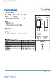
AN44070A• Application Circuit Example0.01 μFBC1BC21415CHARGEPUMP17VPUMP0.01 μFBSTBY34L:Charge Pump off50 kΩBIN2(BBR)BIN1(BFR)323150 kΩ50 kΩGate Circuit5BOUT2RSQQ50 kΩ8RCSBMIFSEL2550 kΩref63BOUT1VM2TJMON123VCCBPWMAPWM3319PWMBLANKOSC TSD UVLO50 kΩ1612VM1AOUT2MRSref10RCSA13AOUT1AIN1(AFR)AIN2(ABR)ASTBY20211850 kΩ50 kΩGate Circuit27GND0.1 μFS5VOUT24VREFVM50 kΩVer. AEB4
AN44070A• Pin DescriptionsPin No.Pin nameTypeDescription1TJMONOutputVBE monitor use2N.C.——3VM2Power supplyMotor power supply 24N.C.——5BOUT2OutputCh. B motor drive output 26BOUT1OutputCh. B motor drive output 17N.C.——8RCSBInput / OutputCh. B current detection9GNDGroundDie pad ground10RCSAInput / OutputCh. A current detection11N.C.——12AOUT2OutputCh. A motor drive output 213AOUT1OutputCh. A motor drive output 114BC1OutputCharge Pump capacitor connection 115BC2OutputCharge Pump capacitor connection 216VM1Power supplyMotor power supply 117VPUMPOutputCharge Pump circuit output18ASTBYInputCh. A Standby input19APWMInputCh. A PWM input20AIN1InputCh. A Forward – Reverse input1 (IFSEL = Low or OPEN)21AIN2InputCh. A Forward – Reverse input2 (IFSEL = Low or OPEN) /Ch. A Brake Mode input (IFSEL = High)22N.C.——23VCCPower supplySignal power supply24S5VOUTOutputInternal reference voltage (5 V output)25IFSELInputInput Mode select26GNDGroundDie pad ground27GNDGroundSignal ground28N.C.——29N.C.——30N.C.——31BIN1InputCh. B Forward – Reverse input1 (IFSEL = Low or OPEN)32BIN2InputCh. B Forward – Reverse input2 (IFSEL = Low or OPEN) /Ch. B Brake Mode input (IFSEL = High)33BPWMInputCh. B PWM input34BSTBYInputCh. B Standby inputVer. AEB5
AN44070A• Absolute Maximum RatingsA No.ParameterSymbolRatingUnitNote1Supply voltage1 (Pin3, Pin16)V M37V*12Supply voltage2 (Pin23)V CC− 0.3 to +6V*13Power dissipationP D0.466W*24Operating ambient temperatureT stg−20 to +70°C*35Storage temperatureT opr−55 to +150°C*36Output pin voltage (Pin5, 6, 12, 13)V OUT37V*47Motor drive current (Pin5, 6, 12, 13)I OUT±2.5A*4, *58Flywheel diode current (Pin5, 6, 12, 13)I fl2.5A*4, *5Notes) *1 : The values under the condition not exceeding the above absolute maximum ratings and the power dissipation.*2 : The power dissipation shown is the value at T a = 70°C for the independent (unmounted) IC package without a heat sink.When using this IC, refer to the P D -T a diagram in the • Technical Data standard and use under the condition not exceeding the allowable value.*3 : Except for the power dissipation, operating ambient temperature, and storage temperature, all ratings are for T a = 25°C.*4 : Do not apply current or voltage from outside to any pin not listed above.In the circuit current, (+) means the current flowing into IC and (−) means the current flowing out of IC.*5 : Four-layer PCB with 1 500 mm 2 of copper ground area on second-layer and third-layer connected with thermal vias and to device exposed pad.If exposed thermal pad is not connected copper ground area, current rating is 1.5 A.• Operating Supply Voltage RangeParameterSymbolRangeUnitNoteOperating supply voltage range1V M10.0 to 34.0V∗Operating supply voltage range2V CC3.0 to 5.5V∗Note) * : The values under the condition not exceeding the above absolute maximum ratings and the power dissipation.Ver. AEB6
AN44070A• Allowed Voltage and Current RangesNotes) • Rating Voltage is voltage of pin on GND• Do not apply current or voltage from outside to any pin not listed above.Pin No.Pin nameRatingUnitNote8RCSB+2.5V—10RCSA+2.5V—14BC1V M + 0.3V—15BC2(V M − 1) to 43V—17VPUMP(V M − 2) to 43V—18ASTBY− 0.3 to 6V—19APWM− 0.3 to 6V—20AIN1− 0.3 to 6V—21AIN2− 0.3 to 6V—24S5VOUT−7 to 0mA—25IFSEL− 0.3 to 6V—31BIN1− 0.3 to 6V—32BIN2− 0.3 to 6V—33BPWM− 0.3 to 6V—34BSTBY− 0.3 to 6V—Ver. AEB7
AN44070A• Electrical Characteristics at V M= 24 V, V CC= 5 VNote) T a = 25°C±2°C unless otherwise specified.B No.ParameterSymbolConditionsMinLimitsTypMaxUnitNoteOutput Drivers1High-level output saturation voltageV OHI = –1.2 AV M–0.63V M–0.42—V—2Low-level output saturation voltageV OLI = 1.2 A—0.550.825V—3Flywheel diode forward voltageV DII = 1.2 A0.51.01.5V—4Output leakage current 1I LEAK1V M =V OUT = 37 V,V RCS = 0 V—1050μA—Power Supply5Supply current1(with two circuits turned off)I M1ASTBY = BSTBY = 0 V—34.5mA—6Supply current2(with two circuits turned on)I M2ASTBY = BSTBY = 5 V—5.37.9mA—7Supply current3(with two circuits turned on)I CCASTBY = BSTBY = 5 V—1.42.2mA—8Reference voltageV S5VOUTI S5VOUT = –2.5 mA4.55.05.5V—9Output impedanceZ S5VOUTI S5VOUT = –5 mA—1827Ω—IN input10High-level IN input voltageV INH—2.2—V CCV—11Low-level IN input voltageV INL—0—0.6V—12High-level IN input currentI INHAIN1 = AIN2 = BIN1 = BIN2= 5 V70—130μA—13Low-level IN input currentI INLAIN1 = AIN2 = BIN1 = BIN2= 0 V–10—10μA—Standby input14High-level STBY input voltageV STBYH—2.2—V CCV—15Low-level STBY input voltageV STBYL—0—0.6V—16High-level STBY input currentI STBYHASTBY = BSTBY = 5 V70—130μA—17Low-level STBY input currentI STBYLASTBY = BSTBY = 0 V–10—10μA—IFSEL input18High-level IFSEL input voltageV IFSELH—2.2—V CCV—19Low-level IFSEL input voltageV IFSELL—0—0.6V—20High-level IFSEL input currentI IFSELHIFSEL = 5 V70—130μA—21Low-level IFSEL input currentI IFSELLIFSEL = 0 V–10—10μA—Ver. AEB8
AN44070A• Electrical Characteristics (continued) at V M=24 V, V CC= 5 VNote) T a = 25°C±2°C unless otherwise specified.BNo.ParameterSymbolConditionsMinLimitsTypMaxUnitNotePWM input22High-level PWM input voltageV PWMH—2.2—V CCV—23Low-level PWM input voltageV PWML—0—0.6V—24High-level PWM input currentI PWMHAPWM = BPWM = 5 V70—130μA—25Low-level PWM input currentI PWMLAPWM = BPWM = 0 V–10—10μA—26PWM Input Max frequencyf PWM———100kHz—27Input Min pulse widtht W—5——μs—Ver. AEB9
AN44070A• Technical Data• Circuit diagrams of the input/output part and pin function descriptionsNote) The characteristics listed below are reference values based on the IC design and are not guaranteed.PinNo.Waveformand voltageInner circuitImpedanceDescription1―10.8k―Pin1 : VBE monitor usePin1 TJMON17568101213―100kPin 5 BOUT26 BOUT112 AOUT213 AOUT1―Pin 5 : Ch. B motor drive output 26 : Ch. B motor drive output 18 : Ch. B current detection12 : Ch. A motor drive output 213 : Ch. A motor drive output 110 : Ch. A current detection100kPin 8 RCSB10 RCSA4kVer. AEB11
AN44070A• Technical Data (continued)• Circuit diagrams of the input/output part and pin function descriptions (continued)Note) The characteristics listed below are reference values based on the IC design and are not guaranteed.PinNo.Waveformand voltageInner circuitImpedanceDescription15014―12514Pin14 BC1―Pin14 : Charge Pump capacitorconnection 1300k1517―1512517―Pin15 : Charge Pump capacitorconnection 217 : Charge Pump circuit outputPin15 BC2Pin17 VPUMPVer. AEB12
AN44070A• Technical Data (continued)• Circuit diagrams of the input/output part and pin function descriptions (continued)Note) The characteristics listed below are reference values based on the IC design and are not guaranteed.PinNo.Waveformand voltageInner circuitImpedanceDescription182534―Pin18 ASTBY25 IFSEL34 BSTBY54k52 kΩPin 18 :Ch. A Standby / Active CTL25 : Input mode selection input34 : Ch. B Standby / Active CTL52k50k192021313233―Pin19 APWM20 AIN121 AIN231 BIN132 BIN233 BPWM4k50k54 kΩPin19 : Ch. A PWM input20 : Ch. A Forward / Reverse input 121 : Ch. A Forward / Reverse input 231 : Ch. B Forward / Reverse input 132 : Ch. B Forward / Reverse input 233 : Ch. B PWM input100kVer. AEB13
AN44070A• Technical Data (continued)• Circuit diagrams of the input/output part and pin function descriptions (continued)Note) The characteristics listed below are reference values based on the IC design and are not guaranteed.PinNo.Waveformand voltageInner circuitImpedanceDescription24―2kPin24 S5VOUT24―Pin24 : Internal reference voltage(5 V output)102kVCC (Pin23)Symbols―VM(Pin3, Pin16)Diode――Zener diodeGroundVer. AEB14
AN44070A• Technical Data (continued)• Control mode (truth table)INPUTOUTPUTIFSELSTBYIN1IN2PWMAOUT1/BOUT1AOUT2/BOUT2Mode"H""H"—"H"“H"Short Brake“L”"H""L""H"“H""L""H""L""H""L""L""H""H""H""H"“H""L"“H"ForwardShort BrakeReverseShort Brake"L""L"—OFFOFFStop“L”———OFFOFFStandbyINPUTOUTPUTIFSELSTBYIN1IN2PWMAOUT1/BOUT1AOUT2/BOUT2Mode—"H""L""H"“H"Short Brake“H”"H""L""H"——"H""H""L""H""H""L"ForwardReverse—"L""L"OFFOFFStop“L”———OFFOFFStandbyASTBY“H”INPUTBSTBY"H"OUTPUTCharge Pump“H”“L"ON“L”"H"“L” “L” OFF *1Note) *1 : Before the motor begins to rotate, install the wait time of 200μs after releasing Standby.Ver. AEB15
AN44070A• Technical Data (continued)• P D ⎯ T a diagramVer. AEB16
AN44070A• Usage Notes1. Perform thermal design work with consideration of a sufficient margin to keep the power dissipation based on supply voltage, load,and ambient temperature conditions.(The IC is recommended that junctions are designed below 70 ∼ 80% of Absolute Maximum Rating.)2. The protection circuit is incorporated for the purpose of securing safety if the IC malfunctions.Therefore, design the protection circuit so that the protection circuit will not operate under normal operating conditions. Thetemperature protection circuit, in particular, may be destructed before the temperature protection circuit operates if the area ofsafety operation of the device or the maximum rating is exceeded instantaneously due to the short-circuiting between the outputpin and VM pin or a ground fault caused by the output pin and ground pin.3. Pay utmost attention to the pattern layout in order to prevent the IC from destruction resulting from the short-circuiting of pins.See page 6 Pin Descriptions for allocations of the pins of the IC.4. When driving a motor coil or transformer (L) load, the device may be destructed as a result of a negative or excessive voltagegenerated at the time of turning the load on and off. Unless otherwise provided in the specifications, do not apply any negativeorexcessive voltage.5. Do not make mistakes in the PCB mounting direction. If power is supplied with the pins mounted in the wrong direction, the ICmay be destructed.6. The IC may be destructed by the solder bridge between the pins of semiconductor devices. Fully make a visual check on the PCBbefore supplying power.Furthermore, the IC may be destructed if conductive foreign matters like solder chips are stuck to the IC during transportationafter PCB mounting. Therefore, conduct full technical verification of the mounting quality of the IC.7. The IC is destructed under an abnormal condition, such as the short-circuiting between the output and VM pins, output and groundpins, or output pins (i.e., load short-circuiting), in which case smoke may be generated. Pay utmost attention to the use of the IC.Pay special attention to the following pins so that they are not short-circuited with the VM pin, ground pin, other output pin, orcurrent detection pin.(1) AOUT1 (Pin13), AOUT2 (Pin12), BOUT1 (Pin6), BOUT2 (Pin5)(2) BC2 (Pin15), VPUMP (Pin17)(3) VM1 (Pin16), VM2 (Pin3), VCC(Pin23), S5VOUT(Pin24)(4) RCSA (Pin10), RCSB (Pin8)The higher the current capacity of power supply is, the higher the possibility of the above destruction or smoke generation.Therefore, it is recommended to take safety countermeasures, such as the use of a fuse.8. When using the IC for model expansion or new sets, be sure to make full safety checks including a long-term reliability check oneach set.9. Set the value of the capacitor between the VPUMP and GND pins so that the voltage on the VPUMP pin (Pin17) will not exceed43 V in any case regardless of whether it is a transient phenomenon or not while the motor standing by is started.10. This IC employs a PWM drive method that switches the high-current output of the output transistor. Therefore, the IC is apt togenerate noise that may cause the IC to malfunction or have fatal damage. To prevent these problems, the power supply must bestable enough. Therefore, the capacitance between the S5VOUT and GND pins must be a minimum of 0.1 μF and the one betweenthe VM and GND pins must be a minimum of 47 μF and as close as possible to the IC so that PWM noise will not cause the IC tomalfunction or have fatal damage.Ver. AEB17
AN44070A• Usage Notes (continued)11. A high current flows into the IC. Therefore, the common impedance of the PCB pattern cannot be ignored. Take the followingpoints into consideration and design the PCB pattern of the motor.A high current flows into the line between the VM1 (Pin16) and VM2 (Pin3) pins. Therefore, noise is generated with ease at thetime of switching due to the inductance (L) of the line, which may result in the malfunctioning or destruction of the IC (see thecircuit diagram on the left-hand side). As shown in the circuit diagram on the right-hand side, the escape way of the noise issecured by connecting a capacitor to the connector close to the VM pin of the IC. This makes it possible to suppress the direct VMpin voltage of the IC. Make the settings as shown in the circuit diagram on the right-hand side as much as possible.VMNoise is generated with easeVMRecommended PCBLow spike amplitudedue tothe capacitancebetweenthe VM pin and ground pinLVMGNDLVMGNDCICRCSCICRCSGNDGND12. In the case of measuring the chip temperature of the IC, measure the voltage of TJMON(Pin1) and presume chip temperature fromfollowing data. Use the following data as reference data. Before applying the IC to a product, conduct a sufficient reliability test ofthe IC along with the evaluation of the product with the IC incorporated.VBE[V]The temperature characteristic of TJMONΔVBE / Δtemp = –1.82 [mV/°C]0150Temp[°C]Ver. AEB18
AN44070A• Usage Notes (continued)13. Power Supply Sequence• If two types of power supply are usedRise : This IC is recommended rise of 5 V power supply before rise of 24 V power supply.Fall : Although there is no particular rule, check that VM fall-time is about 1 s.When recommended sequence is difficult, take the diagram below indicates into consideration and design.Also, rise slew rate designVM : below 0.1V/μs, VCC : below 0.1V/μsPower SupplyVMVCCDelay : below 100 ms1 stime• If one type of power supply is usedRise/Fall slew rate design, VM : below 0.1V/μsPlease check that it is less than 1.0 sec between VCC falling down to 0 volt and VM falling down to 0 volt.14. Charge pump circuit• The charge pump circuit has stopped when the Low signal is input to ASTBY(Pin18) and BSTBY(Pin34).The start time is necessary until the charge pump circuit begins operating. Please take the weight time of 200 μs until the motorstarts rotating after making IC active.VM + 5 VVM – 1.4 VHLVPUMPPWM inputDelay : more than 200 μsHLSTBY input15. PWM operation• The PWM operation of this IC assumes the control by the input switching of APWM (Pin19) or BPWM (Pin33).When AN44070A is operated PWM by using other terminals, the duty of the output is extremely different from the duty of theinput. Please use APWM or BPWM when AN44070A is operated PWM.• When Free Run Mode and Forward/Reverse Mode is repeated in PWM operation, the backflow current flows from GND towardVM. Please add external capacity so as not to exceed the absolute maximum rating of VM.16. IFSEL terminal• Do not switch the terminal IFSEL(Pin25) while IC is active Mode.Please switch IFSEL after the power supply is turned off once or the Low signal is input to ASTBY and BSTBY.17. Check the risk that is caused by the failure of external components.timeVer. AEB19
20100202Request for your special attention and precautions in using the technical information andsemiconductors described in this book(1) If any of the products or technical information described in this book is to be exported or provided to non-residents, the laws andregulations of the exporting country, especially, those with regard to security export control, must be observed.(2) The technical information described in this book is intended only to show the main characteristics and application circuit examplesof the products. No license is granted in and to any intellectual property right or other right owned by <strong>Panasonic</strong> Corporation or anyother company. Therefore, no responsibility is assumed by our company as to the infringement upon any such right owned by anyother company which may arise as a result of the use of technical information described in this book.(3) The products described in this book are intended to be used for general applications (such as office equipment, communicationsequipment, measuring instruments and household appliances), or for specific applications as expressly stated in this book.Consult our sales staff in advance for information on the following applications:– Special applications (such as for airplanes, aerospace, automotive equipment, traffic signaling equipment, combustion equipment,life support systems and safety devices) in which exceptional quality and reliability are required, or if the failure or malfunction ofthe products may directly jeopardize life or harm the human body.It is to be understood that our company shall not be held responsible for any damage incurred as a result of or in connection withyour using the products described in this book for any special application, unless our company agrees to your using the products inthis book for any special application.(4) The products and product specifications described in this book are subject to change without notice for modification and/or improvement.At the final stage of your design, purchasing, or use of the products, therefore, ask for the most up-to-date ProductStandards in advance to make sure that the latest specifications satisfy your requirements.(5) When designing your equipment, comply with the range of absolute maximum rating and the guaranteed operating conditions(operating power supply voltage and operating environment etc.). Especially, please be careful not to exceed the range of absolutemaximum rating on the transient state, such as power-on, power-off and mode-switching. Otherwise, we will not be liable for anydefect which may arise later in your equipment.Even when the products are used within the guaranteed values, take into the consideration of incidence of break down and failuremode, possible to occur to semiconductor products. Measures on the systems such as redundant design, arresting the spread of fireor preventing glitch are recommended in order to prevent physical injury, fire, social damages, for example, by using the products.(6) Comply with the instructions for use in order to prevent breakdown and characteristics change due to external factors (ESD, EOS,thermal stress and mechanical stress) at the time of handling, mounting or at customer's process. When using products for whichdamp-proof packing is required, satisfy the conditions, such as shelf life and the elapsed time since first opening the packages.(7) This book may be not reprinted or reproduced whether wholly or partially, without the prior written permission of our company.