

Aresti manual - Hangar 9
Aresti manual - Hangar 9
Aresti manual - Hangar 9

Create successful ePaper yourself
Turn your PDF publications into a flip-book with our unique Google optimized e-Paper software.
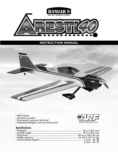
TMWE GET PEOPLE FLYINGTMINSTRUCTION MANUAL• 90% Prebuilt• Hardware included• Precovered in genuine UltraCote ®• Prefinished fiberglass cowl and wheel pantsSpecifications:• Wingspan: ........................................................................................................... 56 in (1422 mm)• Overall Length: ................................................................................................. 49 in (1245 mm)• Wing Area:................................................................................................ 565 sq in (36.5 dm sq)• Weight (approx.): .................................................................................. 4.5–6.0 lb (2.0–2.7 kg)• Recommended Engines: ................................................................................... 2-cycle: .40–.584-cycle: .56–.72
Table of ContentsIntroduction . . . . . . . . . . . . . . . . . . . . . . . . . . . . . . . . . . . . . . 3Warning . . . . . . . . . . . . . . . . . . . . . . . . . . . . . . . . . . . . . . . . 3Additional Required Equipment . . . . . . . . . . . . . . . . . . . . . . . 3Contents of Kit . . . . . . . . . . . . . . . . . . . . . . . . . . . . . . . . . . . . 5Section 1: Hinging the Ailerons . . . . . . . . . . . . . . . . . . . . . . . 6Section 2: Joining the Wing Halves . . . . . . . . . . . . . . . . . . . . 8Section 3: Installing the Aileron Servos . . . . . . . . . . . . . . . . 10Section 4: Installing the Aileron Linkages . . . . . . . . . . . . . . 12Section 5: Mounting the Wing to the Fuselage . . . . . . . . . . . 14Section 6: Installing the Tail(Vertical and Horizontal Stabilizer) . . . . . . . . . . . 17Section 7: Hinging the Horizontal Stabilizer and Elevators . . . 20Section 8: Installing the Tail Wheel and Hinging the Rudder . . 21Section 9: Installing the Rudder and Elevator Control Horns . . 23Section 10: Installing the Main Landing Gear . . . . . . . . . . . . 25Section 11: Assembling and Mounting the Wheel Pants . . . . 26Section 12: Assembling and Installing the Fuel Tank . . . . . . . 28Section 13: Installing the Engine (2-Stroke/4-Stroke) . . . . . . 30Section 14: Installing the Radio . . . . . . . . . . . . . . . . . . . . . . 31Section 15: Installing the Control Linkages . . . . . . . . . . . . . . 33Section 16: Attaching the Cowling . . . . . . . . . . . . . . . . . . . . 37Section 17: Installing the Canopy . . . . . . . . . . . . . . . . . . . . . 39Section 18: Balancing the <strong>Aresti</strong> 40 . . . . . . . . . . . . . . . . . . . 40Section 19: Control Throw Recommendations . . . . . . . . . . . . 40Section 20: Preflight at the Field . . . . . . . . . . . . . . . . . . . . . . 40AMA Safety Code . . . . . . . . . . . . . . . . . . . . . . . . . . . . . . . . . 41IntroductionCongratulations on your purchase of one of the finest ARFs tobe produced! The <strong>Hangar</strong> 9 <strong>Aresti</strong> 40 is a precision sportaircraft, best suited for any modeler who has mastered basicaerobatics. Although this is an ARF (Almost-Ready-to-Fly) kit,it does have some construction features that can be challengingfor a new modeler. If you encounter difficulty in any constructionsequences, please feel free to contact one of our technicians—we stand ready to provide any assistance we can concerning theconstruction of your <strong>Aresti</strong> 40. You can contact us atHorizon Hobby, Inc.4105 Fieldstone RoadChampaign, IL 61822(217) 355-9511www.horizonhobby.comWarningAn R/C aircraft is not a toy! If misused, it can cause seriousbodily harm and damage to property. Fly only in open areas,preferably AMA (Academy of Model Aeronautics) approvedflying sites, following all instructions included with yourradio and engine.Additional Required EquipmentRadio Equipment• 4 channels• 5 servos (JRS537 recommended)• Standard 600-1100mAh receiver battery packRecommended JR ® Systems• JR XF421 EX• JR XP8103• PCM 10SX• JR XP652• PCM 10SXII• PCM 10XJR XF421 EX3
Engine Requirements• .40–.48 2-cycle engines• .56–.72 4-cycle enginesRecommended 2-Cycle Engines• MDS .40 FS Pro• MDS .48 FS Pro• MDS .58 FS ProRecommended 4-Cycle Engine• Saito .56 or .72MDS .48Parts Needed (not included in kit)• Aileron Extension (6") (2)(JRPA094)• Propeller (refer to engine operating instructions for proper size of propeller to use)• Foam for cushioning the fuel tank and radio• Fuel tubing (12")•2 1 / 4 " SpinnerSaito .72Tools and Supplies Needed (not included in kit)Adhesives• Thin CA (cyanoacrylate) glue• CA remover/debonder• 6-minute epoxy• 30-minuet epoxy• Pacer Z-42 Threadlock• Canopy glue (RC-56)Tools• Rubbing alcohol• Epoxy brushes• Paper towels• Drill• Drill Bits: 1/16", 1/8", 1/4"• Phillips screwdriver• Z-bend pliers• Needle-nose pliers• Standard pliers (optional)• Hobby knife with #11 blade• Mixing sticks for epoxy• 90-degree triangle• Medium grit sandpaper• Masking tape (3M blue recommended)• Straight edge• Measuring device (e.g., ruler, tape measure)• Scissors• Wax paper• Felt-tipped pen or pencil• T-pins• Toothpicks• Moto-tool with cutting wheel• Saw blade (#27 Excell recommended)• Antenna tube (optional)4
Contents of KitLarge PartsFADHIGEBCA. FuselageB. Left Wing Half with AileronC. Right Wing Half with AileronD. Vertical Stabilizer with RudderE. Horizontal Stabilizer with Elevators (2)F. CowlG. CanopyH. Wheel PantsI. Main Landing GearOther Parts65437121. Pushrod and Accessories2. Plywood Die-Cut Parts (1/8")3. Hardware Bag4. Wheels5. Fuel Tank and Hardware6. Metal Motor Mount with Hardware7. Wing Joiner5
Section 1: Hinging the AileronsParts Needed• Right wing panel with aileron and hinges• Left wing panel with aileron and hingesTools and Adhesives Needed• Instant thin CA glue• CA remover/debonder• Paper towels• T-pin (one for each hinge)(optional procedure)Note: All control surfaces are pre-hinged, however thehinges are not glued in place. It is imperative that youproperly adhere the hinges and ailerons in place perthe steps that follow using high-quality thin CA glue.Step 1. Carefully remove the tape holding each aileron on thewing panel. Use rubbing alcohol to remove any tape marks.Remove the aileron from one of the wing panels. Note theposition of the hinges. The <strong>Aresti</strong> 40 comes with high qualityCA-type hinges. The hinges are made of a material that helps inthe wicking process when applying CA glue.Step 3. photoStep 4. Deflect the aileron and completely saturate each hingewith thin CA glue. The aileron’s front surface should lightly contactthe wing during this procedure. Ideally, when the hinges areglued in place, a 1/32" gap or less will be maintained throughoutthe length of the aileron to wing panel hinge line.Note: The hinge is constructed of a special materialthat allows the CA to wick or penetrate and distributethroughout the hinge, securely bonding it to the woodstructure of the wing panel and aileron.Step 2. Remove each hinge from the wing panel and aileronand place a T-pin near the center of each hinge. Slide each hingeinto the aileron until the T-pin is snug against the aileron. Thiswill help ensure an equal amount of hinge is on either side of thehinge line when the aileron is mounted to the wing panel.Step 5. Turn the wing panel over and deflect the aileron in theopposite direction and from the opposite side. Apply thin CAglue to each hinge, making sure that the CA penetrates into boththe aileron and wing panel.Step 3. Slide the aileron on the wing panel until there is onlya slight gap. The hinge is now centered on the wing panel andaileron. Remove the T-pins and snug the aileron against thewing panel. This will help ensure the hinges are centered. Agap of 1/32" or less should be maintained between the wingpanel and aileron.6
Step 6. Using CA remover/debonder and a paper towel,remove any excess CA glue that may have accumulated on thewing or in the aileron hinge area.Step 8. After both ailerons are securely hinged, firmly graspthe wing panel and aileron to check to make sure the hingesare securely glued and cannot be pulled out. Do this bycarefully applying medium pressure, trying to separate theaileron from the wing panel. Use caution that you do not crushthe wing structure.Note: Work the aileron up and down several times to“work in” the hinges and check for proper movement.Step 7. Repeat this process with the other wing panel, securelyhinging the aileron in place.7
Section 2: Joining the Wing HalvesParts Needed• Right/left wing panels• Dihedral brace• Wing trim tapeTools and Adhesives Needed• 30-minute epoxy• 6-minute epoxy• Mixing stick• Epoxy brush• Masking tape• Hobby knife w/#11 blade• Rubbing alcohol• Paper towels• Wax paper• Ruler• Felt-tipped pen or pencil• Medium sandpaperStep 3. Place the wing on a large flat surface with the center ofboth wing panels resting on the flat surface. Raise one wing tip1 1 / 2 " from the surface (see illustration below). If necessary, sandthe wing joiner until this is achieved. There should be no gaps inthe wing center. Once you are satisfied with the fit, remove thewing joiner from the wing panels.Step 4. Mix approximately 1 ounce of 30-minute epoxy.Note: It is extremely important to use plenty of epoxywhen joining the wing panels together. It will alsobe helpful to use wax paper under the wing centerwhen epoxying the wing panels together.Step 5. Use an epoxy brush or a scrap piece of wood, apply agenerous amount of epoxy into the wing dihedral cavity in onewing panel.1 1 / 2 "Step 1. Locate the plywood wing joiner. Using the ruler,determine the center of the wing joiner and mark it with afelt-tipped pen or pencil.Step 6. Coat one half of the wing joiner with epoxy up to theline marked in Step 1. Install the epoxy coated side of the dihedralbrace into the wing panel cavity up to the centerline marked.Step 2. Trial fit the wing joiner into one of the wing panels. Itshould insert smoothly up to the centerline marked in Step 1.Now slide the other wing panel onto the wing joiner until thewing panels meet. If the fit is overly tight, it may be necessary tosand the wing joiner.Note: The joiner is flat on one side and tapered on theside that faces the leading edge of the wing.8
Step 7. Apply a generous amount of epoxy into the other wingpanel cavity.Note: You may need to mix up more epoxy to completethe joining process.Step 9. Carefully slide the two wing halves together and firmlypress them together, allowing the excess epoxy to run out. Thereshould not be any gap in the wing halves. Use rubbing alcoholand a paper towel to clean up any excess epoxy.Step 8. Now apply epoxy to all sides of the exposed wingjoiner and uniformly coat both wing roots with epoxy.Step 10. Apply masking tape at the wing joint to hold the winghalves together securely. Place the wing on a flat surface. Withthe center wing panels firmly supported to lie flat on the surface,one wing tip should be propped up so it is 1 1 / 2 " from the surface.Apply more masking tape the center wing joint and recheckthe 2" measurement. Allow the wing joint to dry overnightNote: It is useful to use wax paper underneath the wingcenter while the epoxy is curing. This will help preventexcess epoxy from adhering to the work surface.Step 11. Allow the wing center joint to completely cure, thenremove the masking tape.9
Section 3: Installing the Aileron ServosParts Needed• Assembled wing• Servos (JRPS537 or equivalent) (2)• Servo extensions (6" recommended) (2)• Y-harness (if using a non-computer radio)• String and a weight to run servo extensions through the wingTools and Adhesives Needed• Hobby knife• Phillips screwdriver• Drill• Drill Bit: 1/16"• Masking tape• Electrical tape• Felt-tipped pen or pencilStep 3. With the servo in place, mark the location of the servoscrews used to mount the servo to the plywood servo rail insidethe wing servo opening.Step 1. Locate the servo opening in one of the wing halves.Install the recommended servo hardware supplied with yourradio system onto your servos (grommets and eyelets). Installa 6" servo extension lead to the servo as well. Secure theconnectors by tying a knot in the leads and wrapping withelectrical tape. This will prevent the connectors from becomingaccidentally disconnected inside the wing.Step 4. Using a 1/16"drill bit, drill the servo screw locationsmarked in the previous step.Step 2. Trial fit the servo into the servo opening. Some trimmingmay be required, depending on the type of servo installed.Step 5. Before mounting the servo, it would be wise to run theservo lead and extension through the wing and out the openingprovided near the wing center. The servo lead exits are locatedon the top of the wing. Turn the wing over and look for tworound openings near the center of the wing close to the wingcenter. You will have to trim away the covering to expose theopening. Use a sharp hobby knife to cut away the covering overthe opening. Do the same for the other wing half.10
Step 6. Use a piece of string with a small weight (bolt fromengine mounting hardware) attached as a device to attach to oneend of the servo lead extension and thread through the servoopening through the wing and out the servo lead exit. Othermethods can be used to thread the servo leads through the wing,but we have found this method is the quickest.Step 9. Repeat the procedure for the other wing half.Note: If you are using a non-computer radio, it will benecessary to use a Y-harness to connect both aileronservos to the aileron channel of the receiver.Step 10. Insert the servo into the aileron cutout in the bottomof the wing. Make sure the output shaft of the servo is orientatedclosest to the trailing edge of the wing.Step 7. Once you have threaded the string and weight throughthe wing, attach the string to one end of the servo lead and carefullythread it through the wing. Once you have threaded the leadthrough the wing, you can remove the string so it can be usedfor the other servo lead.Step 11. Use the screws included with the servos to fasten theaileron servos in place.Step 8. To prevent the lead from falling back into the wing, usemasking tape to temporarily hold it in place by taping the lead tothe top of the wing.11
Step 5. Attach the control horn to the aileron using the screwsand the control horn backplate. Be careful not to accidentallypuncture the covering with the screwdriver.Step 7. Make an L-bend in the rod at the location you just marked.Step 6. With the linkage attached to the control horn, centerthe control surface and hold the linkage wire directly over theelectronically centered servo arm. Place a mark on the roddirectly over the hole (second hole from the end of arm) inservo control arm that it will connect to.Step 8. Insert the L-bend through the second hole from the endof the servo arm. Mount wire keeper to retain wire on the servoarm. Install the clevis back onto the control horn. Be sure to slideon the silicon clevis keeper onto the end of the clevis.Step 9. Repeat the process for the other aileron linkage.13
Section 5: Mounting the Wing to the FuselageParts Needed• Wing• Fuselage• Wing hold-down bolt plate• Wing hold-down bolts and washersTools and Adhesives Needed• 30-minute epoxy• Epoxy brush• Rubbing alcohol• Paper towels• Mixing sticks• Felt-tipped pen or pencil• Ruler• Drill• Drill Bit: 1/4"• Round fileStep 1. The assembled wing will slide into the fuselage bottomso that the tab at the leading edge of the wing projects into theslot in the fuselage former at the front of the wing opening inthe fuselage.Step 3. When you’re satisfied the wing is centered, make amark from the wing the center point to the fuselage where thetrailing edge of the wing rests. This will be the center referencepoint for centering the wing in the following steps.Note: We used marking tape for better visibility.Step 2. At the rear of the fuselage opening, measure theopening and mark the center point. With the wing in the fuselagewing opening, line up the wing center with the mark you made.Check to see if the wing is centered on the fuselage bymeasuring from each wingtip to the rear of the fuselage asshown in the illustration below.Step 4. Remove the wing from the fuselage. You will use thewing bolt installed through the bottom of the blind nut to markthe location for the wing on the fuselage. In the fuselage, locatethe wing bolt block with the preinstalled blind nut. Partiallythread the wing bolt through the blind nut from the bottom upuntil the wing bolt is just slightly above the wing saddle.14
Step 5. Carefully install the wing back onto the fuselage withouttouching the wing bolt.Step 7. Remove the wing and the wing bolt from the fuselage.Note the indentation on the bottom of the wing.Step 6. Hold the trailling edge over the bolt aligning the centerof the wing over the mark you previously made on the wing.Carefully lower the trailling edge of the wing until it contactsthe bolt. Gently press down on the trailling edge, to make anindentation on the bottom of the wing, marking where to drillfor the wing bolt.Step 8. Use a 1/4" drill bit and drill the wing hold down bolthole through the wing into the fuselage wing hold down block .Note: You will need to drill at a slight angle, so thedrill is perpendicular to the bottom surface of the wing.15
Step 9. Locate the wing bolt hold-down plate. Note that thewing bolt hold-down plate has a hole already drilled for the wingbolt. Carefully remove the covering over the predrilled openingusing a sharp hobby knife. Position on the wing, being sure toalign the holes, and mark the location of the plate as shown.Step 11. Mix a small amount of 6-minute epoxy and epoxythe wing hold down plate to the wing. Allow the epoxy to curecompletely before attempting the next step.Step 12. Carefully fit the wing in position and tighten down thewing bolt. Check the alignment of the wing as described in Step 2.Note: Adjustments can be made using a round file toopen the wing hold down bolt opening. Make alignmentmarks with a pencil or felt tipped pen to show alignmentof wing to fuselage. This will allow you make sure thewing is centered before each flight.Step 10. Use a sharp hobby knife to trim away the film on thewing where you marked the position of the wing hold downplate. Trim 1/16" inside the mark you made.Caution: Use care in cutting away the film, as cuttinginto the balsa wood can weaken the structure.Step 13. We suggest keeping the wing mounted for the next stepfor alignment purposes.16
Section 6: Installing the Tail(Vertical and Horizontal Stabilizer)Parts Needed• Horizontal stabilizer• Vertical stabilizer• Fuselage/wing assemblyTools and Adhesives Needed• Hobby knife• Ruler• Felt-tipped pen• Pencil• 30-minute epoxy• Paper towels• Rubbing alcohol• Mixing stick• Epoxy brush• Masking tapeNote: Before assembling the tail, be sure theelevator and the CA hinges are removed fromthe horizontal stabilizer. The hinges and elevatorwill be installed later.Step 3. Use a sharp hobby knife to remove the covering fromthe horizontal stabilizer slot in the fuselage.Step 4. Slide the horizontal stabilizer into the slot in thefuselage. With the fuselage resting on a flat surface, align thehorizontal stabilizer by measuring from fixed points on the wingto the outside of the trailing edge tip of the horizontal stabilizer.Be sure that the trailing edge of the horizontal stabilizer stays onits center mark.Mounting the Horizontal StabilizerStep 1. On the rear of the fuselage, slots are precut in the woodfor the vertical stabilizer. The horizontal stabilizer will slide intothe fuselage rear.Step 5. Adjust the stabilizer until you have an equal distance onboth the right and left sides of the stabilizer to the wing.Step 2. Begin by measuring and marking the center of thehorizontal stabilizer on its leading and trailing edge.17
Step 6. When you’re satisfied with the alignment of the horizontalstabilizer with the wing, carefully mark the position with a pencilat the junction where the horizontal stabilizer meets the fuselage.The pencil should leave a slight indentation in the covering.Step 10. Place the fuselage onto a flat surface and position thehorizontal stabilizer onto it, making sure it’s centered and alignedas in Steps 4 and 5.Hint: Reference the bare wood you just exposed tore-align the stabilizer.Step 7. Remove the horizontal stabilizer from the fuselage.Using a hobby knife and a straight edge, carefully cut thecovering approximately 1/16 " inside the lines you drew.Caution: It’s very important that you do not presshard enough to cut into the wood structure, as doingso could weaken the horizontal stabilizer.Use masking tape to hold the horizontal stabilizer in place whilethe epoxy cures.Step 11. Wipe off any excess epoxy using a paper towel andrubbing alcohol. Allow the epoxy to cure fully before proceedingto the next step.Step 8. With the fuselage and horizontal stabilizer together on aflat surface, check to be sure the wing and horizontal stabilizerare aligned with each other as illustrated in Step 4.Step 9. Mix approximately 1/2 ounce (minimum) of 30-minuteepoxy to install the horizontal stabilizer to the fuselage. Using anepoxy brush or mixing stick, spread the epoxy onto the bottomof the horizontal stabilizer where it comes into contact with thefuselage. Also, coat the stabilizer saddle area that will come incontact with the horizontal stabilizer.18
Mounting the Vertical StabilizerStep 12. Remove the rudder and hinges from the verticalstabilizer if you have not already done so. The rudder will beattached (hinged) to the vertical stabilizer later.Step 16. Mix approximately 1/2 ounce (minimum) of 30-minuteepoxy and apply it to the vertical stabilizer where it comes intocontact with the fuselage and horizontal stabilizer. Apply epoxyto the base of the vertical stabilizer where it touches thehorizontal stabilizer.Step 13. Trial fit the vertical stabilizer onto the fuselageand make sure it’s firmly seated down against the horizontalstabilizer. Make sure the rear of the vertical stabilizer (where thehinge slots are located) is aligned with the rear of the fuselage.Step 17. Insert the vertical stabilizer into the fuselage. Wipeaway any excess epoxy with a paper towel and rubbing alcohol.Note: The elevator should not be hinged to thehorizontal stabilizer at this time. It will be attached later.Step 14. Using a pencil or felt-tipped pen, mark the verticalstabilizer on both sides where it meets the fuselage/horizontalstabilizer .Step 18. Use a 90-degree triangle to make sure that the verticalstabilizer is perpendicular to the horizontal stabilizer. Usemasking tape to hold the vertical stabilizer in place while theepoxy cure.Step 15. Remove the vertical stabilizer and carefully cut awaythe covering with a sharp hobby knife just inside the lines youmarked in Step 14.Step 19. The wing can be removed for the convenience of themodeler for the next several steps.Caution: Do not cut into the wood of the verticalstabilizer when cutting the covering, as doing so canweaken the structure.19
Section 7: Hinging the Horizontal Stabilizerand ElevatorsParts Needed• Wing• Elevators (2)• Fuselage with vertical and horizontal stabilizers attachedTools and Adhesives Needed• Thin CA glue• CA remover/debonder• Paper towels• T-pinsStep 3. After the hinges are dry, make sure they are securely inplace by trying to pull the elevator from the horizontal stabilizer.Caution: Use care not to crush the structure.Step 1. Locate the elevators and hinges. Trial fit the elevatorsinto the proper position on the horizontal stabilizer, using thesame hinging techniques learned in Section 1.Step 4. Repeat steps 1-3 for the other elevator half.Step 5. Work the elevators up and down several times to“work in” the hinges and check for freedom of movement.Important: If any binding has developed, it mustbe removed. You may have to trim away somecovering or balsa to make each control surfacemove freely.Step 2. With one elevator half properly aligned (left and right),apply thin CA glue to the hinges on both sides (be sure toremove the T-pins first). Wipe away any excess CA with CAdebonder and a paper towel.20
Step 6. Use needle-nose pliers (or equivalent) to bend a90-degree bend in the tail wheel wire. Remember it should beat a 90-degree angle to the axle of the tail wheel wire. A Zonakeyhole saw and Dremel moto-tool can be used to open a slotat the rear of the fuselage for the nylon tailwheel bearing.Step 7. Trial fit the tail wheel assembly and rudder in place.Deflect the rudder, making sure the tail wheel assembly turnsfreely with the rudder.Step 11. With the rudder and tail wheel assembly installed,apply thin CA to the rudder hinges on both sides, using thesame techniques outlined in Section 2. Be sure to remove theT-pins before applying the CA. There should be a minimal gapbetween the rudder and vertical stabilizer.Step 8. When you’re satisfied with the fit, remove the tail wheelassembly and rudder from the fuselage. Reinstall the hinges inthe rudder using T-pins to make sure the hinges are centered asdescribed in Section 1.Step 9. Mix approximately 1/4 ounce of 30-minute epoxy andapply it both to the nylon bearing where it goes into the fuselageand into the hole in the rudder. With the hinges in place,reassemble the tail wheel assembly and rudder.Hint: A toothpick applicator may be helpful in gettingthe epoxy into the hole.Step 12. Wipe away any excess CA with CA remover/debonder.After the hinges are dry, check to make sure they are securely inplace. Try to pull the rudder from the vertical stabilizer. Use carenot to crush the structure.Step 13. Slide the tail wheel itself onto the tail wheel wire. Nextslide the wheel collar on the wire and tighten the screw in thewheel collar. Place a drop of threadlock on the screw to securethe collar in place.Note: The tail wheel should rotate freely with only asmall amount of side play. Check to be sure the rudderand tail wheel operate smoothly.22Step 10. Make sure the rudder is aligned properly (up anddown) to the fuselage and rudder. Wipe away any excess epoxywith a paper towel and rubbing alcohol. Allow the epoxy to curecompletely before proceeding.
Section 9: Installing the Rudder andElevator Control HornsParts Needed• Control horns (3)• Control horn backplates (3)• Control horn screws (6)• FuselageTools and Adhesives Needed• Drill• Drill Bit: 1/16"• Ruler• Phillips screwdriver (medium)• Felt-tipped pen/pencilStep 2. Place the center of the control horn on the elevator atthe mark made in the previous step. Mark the hole positions ofthe control horn with a felt-tipped pen or pencil.Important: When installing the control horns, it’simportant that the holes in the control horns where thepushrod attaches are directly in line with the controlsurface hinge line.Step 3. Remove the control horn and drill 1/16" holes throughthe elevator as marked.Step 1. To locate the elevator control horn position, measureover 1/2" on the inboard side of the elevator half. Mark theelevator as shown with a felt-tipped pen or a pencil. This markwill be the center of the elevator control horn location. Repeatfor the other elevator half.Step 4. Attach the elevator control horn using the hardwareprovided and fasten in place using a Phillips screwdriver.23
Step 5. Repeat the preceding process for the other elevator half.Step 6. Measure 1/2" from the bottom of the left side of therudder. Mark the location with a felt-tipped pen or pencil. Thismark will serve as the center for the rudder control horn.Step 8. Drill these holes with a 1/16" drill bit and install therudder control horn, using the screws and backplate provided.Step 7. Center the control horn over the mark you’ve just made.Make sure the horn is positioned over the hinge line, just likeyou did for the elevator. Using a felt-tipped pen or pencil, markthe mounting hole locations onto the rudder.24
Section 10: Installing the Main Landing GearParts Needed• Main landing gear (2 pieces)• Fuselage• Landing gear axles with lock nuts (2)• Wheel collar with screw (2)• Landing gear bolts (6)• WashersTools and Adhesives Needed• Felt-tipped pen or pencil• Hobby knife• Round file• Drill• Drill Bit: 5/32"• Phillips screwdriver• ThreadlockNote: The main landing gear is made up of two landinggear sections. Instructions for mounting the wheel pantswill be provided in Section 11.Step 1. Attach the axles to the aluminum landing gear using thelock nuts provided. The wheels will be mounted when the wheelpants are installed.Note: It’s always a good idea to use threadlock on thewheel collar bolts to keep them from coming loose.Step 2. Locate the six predrilled mounting holes in the bottomof the fuselage for mounting the landing gear. The blind nuts arepreinstalled from inside the fuselage. If the covering is over theholes, use a sharp hobby knife and carefully remove the coveringover the pre-drilled holes.Step 3. Bolt the landing gear onto the fuselage with theincluded hardware. Take a bolt and washer and insert itthrough the aluminum landing gear and holes in hatch.Thread the mounting bolts into the preinstalled blind nutsand securely tighten.Note: It’s a good idea to use threadlock on bolt/nuts.25
Section 11: Assembling and Mountingthe Wheel PantsParts Needed• Wheel pants• Wheels (2)• Main landing gear• Mounting hardware packageTools and Adhesives Needed• Ruler• Phillips screwdriver• Drill Bits: 1/4", 3/32", 1/8"• Drill• 30-minute epoxy• Epoxy brush• Mixing stick• Rubbing alcohol• Paper towel• Felt-tipped pen or pencil• Round file (fine)• Sandpaper (medium)Step 1. Locate the two wheel pants and associated hardware.Slide one wheel onto an axle and position them so they arecentered over the wheel opening in one of the wheel pants. Usea felt-tipped pen or pencil to mark the center location of thewheel on each of the wheel pants. This mark will be used as thereference point for marking the mounting holes for the landinggear on the wheel pant.Step 2. Locate the hole for the wheel axle 5/8" measured upfrom the bottom of the wheel pant centered on the mark madein Step 1. Mark with a felt-tipped pen or pencil. Repeat theprocedure for the other wheel pant.Caution: Notice which side of the wheel pant goesagainst the landing gear before making your mark.Note: It may be helpful to remove the main landinggear from the fuselage to make the markings andadjustments in the following steps.Step 3. Trial fit the wheel pant on the landing gear and note thelocation of the main axle. Note the aluminum landing gear has alarge hole (for the axle) and two smaller holes above it. Thesmaller holes will be used to help secure the wheel pant in theproper position relative to the fuselage. Do not mark the smallholes yet.Step 4. Drill the main axle hole using a 1/4" drill bit. It’s helpfulto start with a 1/8" pilot hole first. Once the hole is drilled, trialfit the axle to the opening again. You may have to enlarge thehole further. Use a fine round file to make final adjustments tothe opening. Repeat the process for the other wheel pant.26
Step 5. Locate the axle, lock nut, wheel, and two wheel collars.Mount both axles to the landing gear using the large lock nuts.Step 6. The wheel pant can be trial fitted to the landinggear/axle. You may need to open up the large axle hole a bit witha round file, due to epoxy seeping into the opening Adjust thewheel pant in reference to the bottom of the fuselage so thebottom of the wheel pant is parallel to the bottom of the fuselage.When you’re satisfied with the relationship, mark the small holeopenings onto the wheel pant. This mark can be made by passinga small drill bit through the holes and marking the surface ofthe wheel pant. Remove the wheel pant and drill 3/32" holes inthe wheel pant as marked.Step 7. Repeat Step 9 for the other wheel pant.Step 8. Epoxy the two 4-40 blind nuts into the small holesdrilled in the wheel pant /plywood brace inside the wheel pant.Allow the epoxy to cure completely before attempting to tighten thebolt down.Step 9. Mount the wheel pant to the axle and screw in the two4-40 bolts into the small holes above and below the axle, so thatthey screw into the blind nut. Before tightening the 4-40 bolts,slide on a wheel collar, the wheel and another wheel collar ontothe axle.Step 10. Tighten down the two 4-40 bolts to secure the wheelpant to the landing gear. Position the wheel in the center of thewheel pant opening, and retain it there by positioning the twowheel collars (on either side of the wheel) so that the wheel iskept in the center of the wheel pant opening. Tighten both wheelcollar screws snugly once the wheel is properly positioned.Repeat for the other wheel.Note: A drop of locktite Z-42 on the wheel collarscrews will help keep them from coming lose duringoperation. Repeat the process for the other wheel.27
Section 12: Assembling and Installingthe Fuel TankParts Needed• Clunk (fuel/pickup)• Tube (vent long)• Tube (fuel short)• Tube (fill short) (optional)• Fuel tank• Aluminum cap (large and small)• Stopper• Screw (3 mm)• Silicon tubing (2 green, 1 red)• Silicon tubing (clear, clunk)Tools and Adhesives Needed• Hobby knife with #11 blade• Phillips screwdriver• Tubing bender (optional)Step 3. Locate the other tube. This will be the vent tube. Bendone end up about 60 degrees but no more than 90 degrees.Caution: You can use your fingers to bend the tubing,but be careful not to kink the tubing. If you have accessto a small tubing bender, use it to make the bend.Step 1. Locate the fuel tank parts shown below.Step 4. Slide the vent tube into the other open hole in thestopper and caps.Step 2. Locate the rubber stopper. Insert on of the tubes intoan open hole in the stopper so an equal amount of tubingextends from each side of the stopper. This tube will be the fuelpickup tube that provides fuel to the engine. Slide the smalleraluminum cap onto the tube at one end. Slide the large metalcap over the tube and against the rubber stopper.Note: As an option, the length of the vent and fuelpickup tubes can be trimmed with a tubing cutter.The decision to do so is left up to the modeler. Thefuel tube is provided and is an option. If used, besure to cap after fill in the tank.28
Step 5. Locate the piece of silicone fuel tubing and metalclunk. This tubing will be attached to the clunk making up thefuel pickup inside the tank. Insert the metal clunk into one endof the fuel tubing.Step 8. Carefully insert the stopper into the fuel tank. Positionthe stopper so the vent tube is pointing to the top of the fueltank. The vent tube must point to the top of the tank for the fuelsystem to function properly. Also, move the tank around and upand down to observe the movement of the clunk. It should movefreely and not hit the back of the fuel tank. The fuel clunk mustbe free to move regardless of what attitude the aircraft takes, thusensuring it is in the fuel at all times. If the clunk does not movefreely, trim a portion of the fuel tubing to shorten the length andtry again.Step 6. Install the open end of the fuel tubing onto the fuelpickup tube.Step 9. When you’re satisfied with the movement of the clunkand the vent tube is properly positioned to point to the top of thetank, tighten the 3mm screw so the caps move toward each otherand compress the rubber stopper in the tank stopper opening.This compression will help seal the stopper into the tank opening.Important: You should mark which tube is the vent andwhich is the fuel pickup when you attach fuel tubing to thetubes in the stopper. Once the tank is installed inside thefuselage, it may be difficult to determine which is which.Step 7. Insert the 3 mm screw into the large metal cap.Compress the caps/stopper together and screw the 3 mm screwinto the smaller metal cap. Tighten just enough to hold theassembly together.Step 10. Wrap the fuel tank in foam. This is done to providesupport for the fuel tank, and help reduce vibration. Attach fueltubing the tank tubes and feed the tubing through the hole in thefirewall as you slide the fuel tank into the area behind the firewallin the fuselage.Note: Remove the fuel tank when drilling the hole forthe throttle linkage to prevent accidental puncturing ofthe fuel tank.29
Section 13: Installing the Engine(2-Stroke/4-Stroke)Parts Needed• Fuselage• Engine• Engine mounting bracket (2)• Engine mounting screws, nuts, and washers (4 each)Tools and Adhesives Needed• Phillips screwdriver• Blue Locktite A-42Step 3. Insert one 4 x 20mm screw and washer into each of theengine mounting bracket holes. Note these are designed so thenuts at the bottom fit into place. Press one of the 4 mm nuts intothe corresponding receptacle on the bottom of the motor mount.Do not use Blue Locktite A-42 on the screws yet, as you willneed to make minor adjustments to the motor position when youare measuring and mounting the cowling. It may be necessary tomount, then remove the muffler as you make trial fittings of thecowl. The spinner will be mounted after the cowling is in place.Step 1. Remove the two engine mounting brackets, four4 x 20 mm screws, four washers, and four 4 mm nuts from thehardware package.Step 2. Position the engine on the motor mount. Thenplace one engine mounting bracket across each of the enginemounting beams as shown below.Note: The dimpled side of the engine-mounting bracketis the bottom. As such, the smooth side should face upward.30
Section 14: Installing the RadioParts Needed• 4-channel radio system with 5 servos and hardware(not included)• Radio-packing foam (not included)• Antenna tube (optional, not included)Tools and Adhesives Needed• Drill• Drill Bit: 1/16"• Phillips screwdriver• Hobby knife with #11 blade• Felt-tipped pen or pencilStep 3. Once you are satisfied with the servo’s location,use a felt-tipped pen or pencil to mark the mounting holes forall three servos.Step 1. Locate grommets and eyelets for the servos and mountper the instructions included with the radio.Step 2. Locate the plywood servo tray mounted in the fuselage.Trial fit the servos in place, with the rudder and elevator servosin place along the sides of the fuselage, and the throttle servotoward the front of the fuselage in the direction of the fuel tank.Note the orientation of the servo arms.Step 4. Remove the servos and drill 12 holes using a 1/16"drill bit. Remount the servos and screw in the mounting screwsprovided with the servos.31
Step 5. Use radio-packing foam (available at your local hobbyshop) when you install the receiver and battery pack. There isample room for the receiver and battery in the forward part ofthe fuselage, in the area above and behind the fuel tank. Wrapthe battery and receiver securely in foam and install them intothe fuselage. We suggest mounting the receiver on top of thebattery pack using a rubber band to hold in place. Refer to thephotos below.Step 6. Route the antennae back through the fuselage usingan antenna tube (not included), or route it out the side of thefuselage, back toward the tail. Install the switch to the bottom ofside of the plywood servo tray (a notch has been cut for you) anduse a Du-Bro On/Off switch rod to activate the switch throughthe fuselage side on a piece of music wire as shown below.Another option is to mount the switch to the fuselage side. Youmay need to use a piece of scrap wood to mount the switch andthen mount to side of the fuselage. Be sure to mount away fromthe muffler.32
Section 15: Installing the Control LinkagesParts Needed• Fuselage• Balsa dowels• Heat-shrink tubing• Threaded rod (1/16") (4)• Plain rod (1/16")• Nylon tube• Plastic clevis (4)• EZ ConnectorTools and Adhesives Needed• Thin CA glue• Nylon thread• Drill• Drill Bit: 1/16", 1/8"• Heat gun• Hobby knife• Needle-nose pliers• Z-bend pliers• Felt-tipped pen or pencil• Phillips screwdriver• RulerStep 3. Drill a 1/16" hole through the balsa dowels at the twomarked positions, as shown below.Step 4. Select one of the dowels and make a second mark 1 1 / 4 "from the end. This dowel will be used to make up the elevatorpushrod, which has two rods so the split elevators can be activated.Step 1. Locate the parts that make up the pushrods.Step 5. Drill a 1/16" hole at this mark, next to the first holedrilled at that end. Refer to the illustration below.Step 2. Using a felt-tipped pen or pencil, mark 1" from one endof both dowel rods (two places). Repeat marking 1" from theend, but 90° marked to first hole marked on body rods.33
Step 6. Locate the following rods: two long threaded rods andone short non-threaded rod. These will be used to make up theelevator pushrod assembly.Step 9. Slip a piece of heat shrink tubing over the end of therod and shrink in place using a heat gun.Step 7. Position the two long threaded rods so they are evenat the threaded end and wrap in position on the dowel withmasking tape. Mark each rod where it passes the holes drilledin the end of the dowel. Remove the rods and make a 90-degreebend in the unthreaded end where you made your marks.Step 10. Locate the unthreaded short rod, make a 90-degreebend in one end and attach to the opposite end of the elevatorpushrod dowl in the same manner as described in Steps 8 and 9.Step 11. The rudder pushrod is constructed in the samemanner as the elevator pushrod, except it uses only one longthreaded rod and one short non-threaded rod.Step 8. It’s helpful to make a grove from the holes to the end ofthe dowl to help secure the music wire rods. Place each rod intheir respective holes. Wrap nylon thread around the rods andsecure in place with thin CA glue.Step 12. Carefully remove the covering at the tail of the fuselagewhere the two elevator pushrods exit (both sides of thefuselage) and the rudder pushrod (on the right side of the fuselageas if you were sitting in the cockpit).34
Step 13. Spread the two threaded pushrods apart (elevatorpushrod) approximately 1 1 / 2 " apart. Insert the elevator pushrodinto the fuselage, threaded end first, so that the threaded rodscome out of the elevator pushrod exits in the fuselage. Thread anylon clevis on each rod 12-16 turns. Attach each clevis to anelevator control horn’s outermost hole. It’s a good idea to place apiece of fuel tubing (7 mm long) over each clevis to prevent theclevis from accidentally coming open in flight.Step 16. Using pliers, make an L-bend at the marked locationson the elevator and rudder pushrods. Cut off any excess rod.Step 17. Insert the L-bend into the servo arm of the elevatorand rudder servos as shown below. It may be necessary to enlargethe servo arm holes slightly to accept the nylon wire keeper.Step 14. Insert the rudder pushrod threaded end first into thefuselage so that it exits the right side of the fuselage near therudder control horn. Thread a nylon clevis onto the threaded end12-16 turns then attach it to the rudder control horn’s outermosthole. Be sure to place a piece of fuel tubing over the clevis toprevent it from coming open accidentally.Step 15. Center the elevator, rudder, and throttle servos byturning on the transmitter, then the receiver. Position the servoarms so they are 90 degrees to the pushrod assemblies. Use afelt-tipped pen or pencil to mark where the unthreaded ends ofthe rudder and elevator pushrods pass their respective servo arm.35
Step 18. To install the throttle pushrod, locate the wire throttlepushrod and make a Z-bend at one end. This will be used toconnect the carburator and to the throttle servo. Mount theengine and locate the point where the throttle linkage mustexit the firewall to connect directly to the throttle arm on thecarburator. Mark this point.Step 20. After drilling the hole in the firewall, slide the plastictubing through the hole and secure in place with CA. Insert thewire throttle linkage into the nylon tube from the front of themodel and attach to the throttle arm.Step 19. Remove the fuel tank so you do not accidentally drillthrough it and drill a 1/8" hole in the firewall of the marked point.Step 21. Install the EZ Connector onto the throttle servo arm.Position the throttle servo at neutral position, set the carbratorarm at 1/2 throttle, and tighten the EZ Connector.36
Section 16: Attaching the CowlingParts Needed• Fuselage• Fiberglass cowl• Machine head screws (4)Tools and Adhesives Needed• Drill• Drill Bit: 1/16"• Masking tape• Moto-tool with sanding drum• Carbide cutter• Ruler• Sanding stick (medium)• Felt-tipped pen or pencilStep 1. Cut out a U-shaped opening in the bottom of the cowl.This will also allow for air flow around the cylinder. A templatefor the cowl opening is also provided.Step 3. Use a moto-tool and a carbide cutter to make thecylinder head and needle valve openings in the cowl.Note: We have shown an MDS .40 glow enginemounted in the <strong>Aresti</strong> 40. If you use a different engine,it will be necessary to make the appropriate templateand mark the cowl to fit the engine you have.Step 4. Mount the engine in the aircraft. Slide the cowl ontothe fuselage. Trial fit the cowl to the engine installed. Mountthe muffler and trial fit again. Make sure the engine is mountedso the prop drive hub is 4 5 / 8 " from the firewall. This shouldprovide a approximately 3/16" clearance between the cowl andthe spinner backplate when mounted on the engine. Re-adjustthe cowl or engine on motor mount if necessary to obtain theproper clearance.Step 5. Tape the cowl securely in position and check to makesure it fits correctly. There should be ample (1/8" around theengine and muffler) clearance. Check to make sure the prop hubis centered in the opening in the cowl.Step 6. There will be two hold-down screws located on eitherside of the cowl. With the cowl in position, the top screw islocated 1/2" from the edge of the cowl to the front. The bottomscrew is located below the top screw, as shown at a location1/2" from the edge of the cowl.Step 2. Make a template of the cylinder head of the engine youare going to mount in the <strong>Aresti</strong> 40 . Mount the engine andplace the template over it. Use a piece of cardboard or heavypaper that can be taped to the fuselage and folded back. Removethe engine, fold back the template and slide the cowl over thefuselage. Unfold the template so it rests on the cowl at the positionwhere the engine cylinder will be located. Mark the cowl forthe engine cylinder opening. The same process can be done tolocate where the needle valve will exit the cowl.37
Step 7. Once the mounting holes have been marked, drill theholes on each side of the cowl using a 1/16" drill bit. Be sure touse masking tape to hold the cowl securely in positionStep 8. Remove the cowling and enlarge the four holes in thecowling just enough to fit the rubber grommets in place.Note: On some engines where the carburetor is noteasily accessible, a removable fueling valve can beused. Du-Bro’s Kiwi-Fill Fueling Valve (DUB334) isan excellent choice and should be available at yourlocal hobby shop.Step 9. Align the cowling on the fuselage and secure it withthe screws.38
Section 17: Installing the CanopyParts Needed• Assembled aircraft• Plastic canopy• Mounting screws (small) (4)• Trim tapeTools and Adhesives Needed• Sharp hobby knife• Scissors• Canopy glue (Pacer 560)• Phillips screwdriverStep 3. Trim as necessary to make for a good fit. When you’resatisfied with the fit, attach the canopy with canopy glue. Usemasking tape to hold the canopy in place while the glue cures.Step 1. Locate the canopy.Step 2. Trial fit the canopy carefully along the fuselage and usea felt-tipped pen to mark where the canopy should be trimmed.39
Section 18: Balancing the <strong>Aresti</strong> 40 An extremely important step in preparing an aircraft for flight isensuring it is properly balanced. Do not neglect this step. Eachindividual’s <strong>Aresti</strong> 40 will not be the same because of the variouscombinations of engines that can be used, servos, radio equipment,type of hardware used, and assembly methods used during buildingof the <strong>Aresti</strong> 40. Always check the center of gravity (CG) with thefuel tank empty.The recommended CG location for the <strong>Aresti</strong> 40 is 3 1 / 2 " to 3 3 / 4 "behind the leading edge of the wing measured at the fuselage.If necessary, add weight or move the batteries to either thenose or the tail until the correct balance is achieved. Stick-onweights are available at your local hobby shop and work wellfor this purpose.Section 19: Control Throw RecommendationsThe following control throw recommendations offer positive response and are a good place to begin setting up the aircraft. After youhave become more familiar with the flight characteristics of the Paranoid, adjust the control throws to meet your flying style.• AileronLow Rate3/8" Up, 1/4" DownHigh Rate5/8" Up, 3/8" Down• ElevatorLow Rate3/8" Up, 3/8" DownHigh Rate5/8" Up, 5/8" Down• RudderLow Rate1 1 / 4 " Right, 1 1 / 4 " LeftHigh Rate2 1 / 4 " Right, 2 1 / 4 " LeftSection 20: Preflight at the FieldRange Test Your Radio1. Before each flying session, be sure to range check your radio.This is accomplished by turning on your transmitter with theantenna collapsed. Turn on the radio in your airplane. Withyour airplane on the ground, you should be able to walk30 paces away from your airplane and still have completecontrol of all functions. If not, don’t attempt to fly! Have yourradio equipment checked out by the manufacturer.Adjusting the Engine1. Completely read the instructions included with your engineand follow the recommended break-in procedure. At the fieldadjust the engine to a slightly rich setting at full throttle andadjust the idle and low-speed needle so that a consistent idleis achieved. Before you fly, be sure that your engine reliablyidles, transitions, and runs at all throttle settings. Only whenthis is achieved should any plane be considered ready for flight.402. Double-check that all controls (aileron, elevator, throttle,rudder, etc.) move in the correct direction.3. Be sure that your batteries are fully charged per the instructionsincluded with your radio.
AMA Safety Code 2001 Official AMA National Model Aircraft Safety Code Effective January 1, 2001Model flying must be in accordance with this Code in order forAMA Liability Protection to apply.General1. I will not fly my model aircraft in sanctioned events, air shows,or model flying demonstrations until it has been proven to beairworthy by having been previously, successfully flight tested.2. I will not fly my model higher than approximately 400 feetwithin 3 miles of an airport without notifying the airportoperator. I will give right-of-way and avoid flying in theproximity of full-scale aircraft. Where necessary, anobserver shall be utilized to supervise flying to avoidhaving models fly in the proximity of full-scale aircraft.3. Where established, I will abide by the safety rules for theflying site I use, and I will not willfully and deliberately flymy models in a careless, reckless, and/or dangerous manner.4. At all flying sites, a straight or curved line(s) must beestablished in front of which all flying takes place, withthe other side designated for spectators. Only personnelinvolved with flying the aircraft are allowed in front of theflight line. Flying over the spectator side of the line isprohibited, unless beyond the control of the pilot(s). Inany case, the maximum permissible takeoff weight of themodels with fuel is 55 pounds.5. At air shows or model flying demonstrations, a singlestraight line must be established, one side of which is forflying and the other side for spectators. Only those personsaccredited by the contest director or other appropriateofficial as necessary for flight operations or as having dutiesor functions relating to the conduct of the show ordemonstration are to be permitted on the flying side of theline. The only exceptions which my be permitted to thesingle straight line requirements, under special circumstancesinvolving consideration of side conditions and model size,weight, speed, and power must be jointly approved by theAMA president and the executive director.6. Under all circumstances, if my model weighs over 20pounds, I will fly it in accordance with paragraph 5 of thissection of the AMA Safety Code.7. I will not fly my model unless it is identified with my nameand address or AMA number, on or in the model. This doesnot apply to models while being flown indoors.8. I will not operate models with metal-bladed propellers orwith gaseous boosts, in which gases other than air entertheir internal combustion engine(s); nor will I operatemodels with extremely hazardous fuels such as thosecontaining tetranitromethane or hydrazine.9. I will not operate models with pyrotechnics (any devicethat explodes, burns, or propels a projectile of any kind)including, but not limited to, rockets, explosive bombsdropped from models, smoke bombs, all explosive gases(such as hydrogen-filled balloons), ground mounteddevices launching a projectile. The only exceptions permittedare rockets flown in accordance with the National ModelRocketry Safety Code or those permanently attached (as perJATO use); also those items authorized for Air Show Teamuse as defined by AST Advisory Committee (documentavailable from AMA HQ). In any case, models using rocketmotors as primary means of propulsion are limited to amaximum weight of 3.3 pounds and a G series motor. Amodel aircraft is defined as an aircraft with or withoutengine, not able to carry a human being.10. I will not operate any turbo jet engine (axial or centrifugalflow) unless I have obtained a special waiver for such specificoperations from the AMA President and ExecutiveDirector, and I will abide by any restriction(s) imposed forsuch operation by them. (This does not apply to ducted fanmodels using piston engines or electric motors.)11. I will not consume alcoholic beverages prior to, nor during,participation in any model operations.Radio Control1. I will have completed a successful radio equipment groundrange check before the first flight of a new or repaired model.2. I will not fly my model aircraft in the presence of spectatorsuntil I become a qualified flier, unless assisted by an experiencedhelper.3. I will perform my initial turn after takeoff away from the pitor spectator areas, and I will not thereafter fly over pit orspectator areas, unless beyond my control.4. I will operate my model using only radio control frequenciescurrently allowed by the Federal CommunicationsCommission. (Only properly licensed amateurs are authorizedto operate equipment on Amateur Band frequencies.)5. I will not knowingly operate an R/C system within 3 milesof a pre-existing model club-flying site without a frequencysharing agreement with that club.6. Models flown in air-to-air combat are limited to maximumtotal engine displacement of .30 cubic inches and amaximum dry weight prior to flying of 4 pounds.Organized RC Racing Event7. An RC racing event, whether or not an AMA rule bookevent, is one in which model aircraft compete in flight overa prescribed course with the objective of finishing thecourse faster to determine the winner.A. In every organized racing event in which contestants,callers and officials are on the course:1. All officials, callers and contestants must properly wearhelmets which are OSHA, DOT, ANSI, SNELL or NOCASEapproved or comparable standard while on the race course;2. All officials will be off the course except the starter andhis/her assistant.3. “On the course” is defined to mean any area beyond thepilot/staging area where actual flying takes place.B. I will not fly my model aircraft in any organized racing eventwhich does not comply with paragraph A above or whichallows models over 20 pounds unless that competitionevent is AMA sanctioned.41
42NOTES
© Copyright 2001, Horizon Hobby, Inc.(217) 355-9511www.horizonhobby.com


