DMC - BIBUS SK, sro
DMC - BIBUS SK, sro
DMC - BIBUS SK, sro

Create successful ePaper yourself
Turn your PDF publications into a flip-book with our unique Google optimized e-Paper software.
HEAD OFFICE<br />
INMOTION TECHNOLOGIES AB<br />
Solkraftsvägen 13<br />
SE-135 70 Stockholm<br />
SWEDEN<br />
Telephone: +46 (0)8 682 64 00<br />
Telefax: +46 (0)8 682 65 80<br />
Info@inmotech.com<br />
http://www.inmotech.com<br />
APPLICATIONS CENTERS<br />
GREAT BRITAIN<br />
Inmotion Technologies<br />
/Danaher Motion<br />
Bridge Mills<br />
Holmfirth<br />
Huddersfield<br />
HD9 3TW<br />
Telephone: +44 (0)1484 68 83 25<br />
Telefax: +44 (0)1484 68 83 26<br />
GERMANY<br />
ACC Motion GmbH<br />
Zähringerstrasse 23<br />
DE-77654 Offenburg<br />
Telephone: +49 (0)781 919 08-0<br />
Telefax: +49 (0)781 919 08-29<br />
ITALY<br />
ACC Motion Srl<br />
c/o Fluke Slr<br />
Viale delle Industrie 11<br />
IT-20090 Vimodrone (MI)<br />
Telephone: +39 02 25 00 161<br />
Telefax: +39 02 25 00 450<br />
SWEDEN<br />
Inmotion Technologies AB<br />
Solkraftsvägen 13<br />
SE-135 70 Stockholm<br />
Telephone: +46 (0)8 682 64 00<br />
Telefax: +46 (0)8 682 65 80<br />
Inmotion Technologies AB<br />
Box 195<br />
SE-234 23 Lomma<br />
Telephone: +46 (0)40 41 48 50<br />
Telefax: +46 (0)40 41 48 55<br />
SWITZERLAND<br />
ACC Motion SA<br />
Wehntalerstrasse 6<br />
CH-8154 Oberglatt<br />
Telephone: +41 (0)1 851 5010<br />
Telefax: +41 (0)1 851 5020<br />
ACC Motion SA<br />
La Pierreire<br />
CH-1029 Villars-Ste-Croix<br />
Telephone: +41 (0)21 863 6464<br />
Telefax: +41 (0)21 863 6479<br />
U.S.A.<br />
Inmotion Technologies<br />
211 Overlock Drive<br />
Sewickley, PA 15143-2305<br />
Telephone: +1 (412) 749 0710<br />
Telefax: +1 (412) 749 0705<br />
<strong>DMC</strong> 2<br />
Digital Motion Controller<br />
<strong>DMC</strong> 2 Connection<br />
Art.No. 9032 0027 11<br />
21.03.2001<br />
Inmotion Technologies AB<br />
Stockholm, Sweden<br />
© Inmotion Technologies AB, 2001.<br />
All rights reserved.
2<br />
<strong>DMC</strong> 2 Connection Inmotion Technologies AB<br />
Doc. No.9032 0027 11 Rev. 21.03.2001
Table of Contents<br />
Table of Contents...............................................................................3<br />
<strong>DMC</strong> 2 Connections.............................................................................5<br />
General ..................................................................................................................5<br />
X Connector’s ........................................................................................................6<br />
DSUB Connector’s .............................................................................................6<br />
<strong>DMC</strong> 2 Front ............................................................................................................7<br />
<strong>DMC</strong> 2 I/O Connections...........................................................................................8<br />
<strong>DMC</strong> 2 50412/P, <strong>DMC</strong> 2 50720/P .............................................................................9<br />
<strong>DMC</strong> 2 51540/P, <strong>DMC</strong> 2 53080 ..............................................................................10<br />
Power Supply 580160..........................................................................................11<br />
X1.........................................................................................................................11<br />
X2.........................................................................................................................12<br />
X4 (host) ..............................................................................................................12<br />
X5 (next) ..............................................................................................................13<br />
X4 and X5 connection..........................................................................................13<br />
RS 232 Interface ..............................................................................................13<br />
Communication between <strong>DMC</strong> 2 .......................................................................13<br />
LAN 1 communication ......................................................................................14<br />
X6A ......................................................................................................................14<br />
Resolver and external resolver connection ......................................................15<br />
Resolver Connection from motor ..................................................................15<br />
External resolver ...........................................................................................15<br />
Syncbox............................................................................................................15<br />
X6B ......................................................................................................................15<br />
X7A/B...................................................................................................................16<br />
Pinouts user I/O................................................................................................17<br />
X8A ......................................................................................................................17<br />
X9A ......................................................................................................................18<br />
X10.......................................................................................................................18<br />
X11.......................................................................................................................19<br />
X13.......................................................................................................................19<br />
X14.......................................................................................................................20<br />
X20.......................................................................................................................20<br />
X21.......................................................................................................................20<br />
X22.......................................................................................................................21<br />
X23.......................................................................................................................21<br />
X31.......................................................................................................................22<br />
X32 & X33............................................................................................................22<br />
<strong>DMC</strong> 2 50412 or <strong>DMC</strong> 2 50720 DC Bus Connection ..........................................22<br />
<strong>DMC</strong> 2 51540 or <strong>DMC</strong> 2 53080 DC Bus Connection ..........................................23<br />
X34.......................................................................................................................23<br />
X35.......................................................................................................................24<br />
Input wiring diagram.............................................................................................25<br />
Single Installation .............................................................................................25<br />
<strong>DMC</strong> 2 -P/ <strong>DMC</strong> 2 Installation...............................................................................25<br />
Power Supply/<strong>DMC</strong> 2 50412, 50720 Installation ...............................................26<br />
Power Supply/<strong>DMC</strong> 2 51540, 53080 Installation ...............................................27<br />
<strong>DMC</strong> 2 Connection Inmotion Technologies AB<br />
Doc. No.9032 0027 11, Rev. 21.03.2001<br />
3
<strong>DMC</strong> 2 Connections<br />
GENERAL<br />
This section provides details for connecting the <strong>DMC</strong> 2 to motor connections, power,<br />
dynamic brake, thermistor /brake, DC Bus, I/O, Daisy chain, LAN 2 and integral<br />
resolver.<br />
The motor cable connector nomenclature and location is different<br />
for the various <strong>DMC</strong> 2 models.<br />
WARNING<br />
♦ Failure in properly ground this equipment could result is<br />
serious or fatal injury to personnel who come into contact<br />
with the equipment. All earth grounds must be installed per<br />
the instructions in this chapter, and the equipment must be<br />
securely connected to a quality earth ground before power is<br />
applied for the first time. In addition, the panel or enclosure<br />
housing the equipment must be securely earth grounded.<br />
♦ Local regulations may require additional grounding measures<br />
beyond those shown in this chapter.<br />
♦ Failure to properly ground the equipment may result in<br />
damage to the equipment or damage to other devices<br />
connected to the equipment.<br />
WARNING<br />
♦ This equipment uses high voltages, which can cause serious<br />
or fatal electrical shock.<br />
♦ Can cause serious or fatal injury.<br />
♦ Only qualified personnel should perform installation and<br />
wiring.<br />
<strong>DMC</strong>2 Connection Inmotion Technologies AB<br />
Doc. No.9032 0027 11, Rev. 21.03.2001 5
6<br />
X Connector’s<br />
X CONNECTOR’S<br />
<strong>DMC</strong>2 CONNECTIONS<br />
Connector Function Interface Page<br />
X1 Input power 11<br />
X2 + 24 V External DC 12<br />
X4 Host RS 232, RS 422, LAN 1, X5 12<br />
X5 Next RS 232, RS 422, LAN 1, X4 13<br />
X6A Resolver, Feedback 14<br />
X6B Optional.Position.Sensor Available only for <strong>DMC</strong>2 CAN 15<br />
X7A I/O 16<br />
X7B I/O 16<br />
X8A Measure connection Available only for <strong>DMC</strong>2 CAN<br />
X9 LAN2 Available only for <strong>DMC</strong>2 CAN 18<br />
X10 DC Bus X10P, X32, X33 18<br />
X11 Motor 19<br />
X13 Dynamic brake X34 19<br />
X14 Thermistor/brake X35 20<br />
X20 DC Bus X20P, X32, X33 20<br />
X21 Motor 20<br />
X22 Dynamic brake X34 21<br />
X23 Thermistor/brake X35 21<br />
X31 Input power 22<br />
X32 DC Bus X10, X20 22<br />
X33 DC Bus X10, X20 22<br />
X34 Dynamic brake X13, X22 23<br />
X35 Thermistor/brake<br />
Temperature switch<br />
DSUB CONNECTOR’S<br />
<strong>DMC</strong>2 Connection Inmotion Technologies AB<br />
Doc. No.9032 0027 11, Rev. 21.03.2001<br />
17<br />
X14, X23 24<br />
Connector D-Sub miniature in Metal housing Pin Male Female<br />
X4 and X5 High Density, VGA 15 X<br />
X6A Standard 15 X<br />
X6B Standard 25 X<br />
X8A Standard 9 X<br />
X9 Standard 9 X
<strong>DMC</strong>2 CONNECTIONS<br />
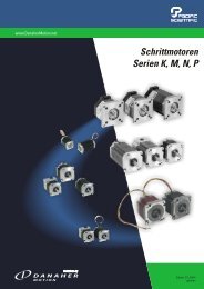
<strong>DMC</strong> 2 FRONT<br />
Figure 1. <strong>DMC</strong> 2 Front and Connections.<br />
<strong>DMC</strong>2 Front<br />
<strong>DMC</strong>2 Connection Inmotion Technologies AB<br />
Doc. No.9032 0027 11, Rev. 21.03.2001<br />
7
8<br />
<strong>DMC</strong>2 I/O Connections<br />
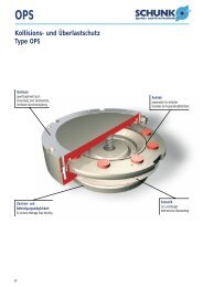
<strong>DMC</strong> 2 I/O CONNECTIONS<br />
Figure 2. I/O Connections for all <strong>DMC</strong> 2 units, bottom view.<br />
<strong>DMC</strong>2 CONNECTIONS<br />
<strong>DMC</strong>2 Connection Inmotion Technologies AB<br />
Doc. No.9032 0027 11, Rev. 21.03.2001
<strong>DMC</strong>2 CONNECTIONS<br />
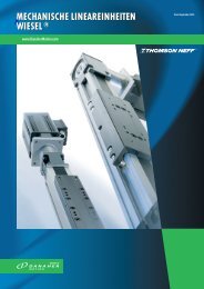
<strong>DMC</strong> 2 50412/P, <strong>DMC</strong> 2 50720/P<br />
<strong>DMC</strong>2 50412/P, <strong>DMC</strong>2 50720/P<br />
Figure 3. <strong>DMC</strong> 2 unit connectors on the topside, Motor, Power, Thermistor, DC Bus<br />
for 50412/P and 50720/P.<br />
<strong>DMC</strong>2 Connection Inmotion Technologies AB<br />
Doc. No.9032 0027 11, Rev. 21.03.2001<br />
9
10<br />
<strong>DMC</strong>2 51540/P, <strong>DMC</strong>2 53080<br />
<strong>DMC</strong> 2 51540/P, <strong>DMC</strong> 2 53080<br />
<strong>DMC</strong>2 CONNECTIONS<br />
Figure 4. <strong>DMC</strong> 2 unit connectors on the topside, Motor, Power, Thermistor, DC Bus<br />
for 51540/P and 53080.<br />
<strong>DMC</strong>2 Connection Inmotion Technologies AB<br />
Doc. No.9032 0027 11, Rev. 21.03.2001
<strong>DMC</strong>2 CONNECTIONS<br />
POWER SUPPLY 580160<br />
Power Supply 580160<br />
Figure 5. PS 580160 unit connectors on top side, Power, Dynamic brake and<br />
Thermistor.<br />
X1<br />
<strong>DMC</strong> 2 P 50412 50720 51540<br />
<strong>DMC</strong> 2 50412 50720 51540 53080<br />
Connector See User’s Manual part A.<br />
Input power is connected to X1 Figure 3 or Figure 4 on top of the <strong>DMC</strong> 2 unit as<br />
shown in Figure 7 for a Single and Figure 8 for a Master/Follower application.<br />
Connect <strong>DMC</strong> 2 5xxxxP models to 400 VAC mains.<br />
<strong>DMC</strong> 2 X1 Function<br />
1 PE<br />
2 Phase L1<br />
3 Phase L2<br />
4 Phase L3<br />
Table 1. Connection Mains to <strong>DMC</strong> 2 .<br />
<strong>DMC</strong>2 Connection Inmotion Technologies AB<br />
Doc. No.9032 0027 11, Rev. 21.03.2001<br />
11
12<br />
X2<br />
X2<br />
<strong>DMC</strong> 2 P 50412 50720 51540<br />
<strong>DMC</strong> 2 50412 50720 51540 53080<br />
<strong>DMC</strong>2 CONNECTIONS<br />
Connector See User’s Manual part A.<br />
Connections for 24V external logic supply voltage. When connected, it supplies the<br />
internal control circuit, feedback sensors, communication and I/O ports.<br />
The 24V logic supply shall always be connected before the main supply voltage is<br />
connected to the input power port. External fuse shall be used rated max 1.5A T<br />
(slow).<br />
<strong>DMC</strong> 2 X2 Function Remark<br />
1 0 V Supply Internal connected to X7A,pin 5<br />
2 + 24 V Supply,<br />
+20%: -20%, maximum supply<br />
current 0.7A (not including load<br />
on digital outputs)<br />
Table 2. External +24 V Connection to <strong>DMC</strong> 2 .<br />
X4 (HOST)<br />
<strong>DMC</strong> 2 P 50412 50720 51540<br />
<strong>DMC</strong> 2 50412 50720 51540 53080<br />
Internal connected to X7B, pin 25<br />
Connector See page 6<br />
X4 is used for connections between external PC and other <strong>DMC</strong> 2 units.<br />
i The maximum length for this cable is 15 m.<br />
<strong>DMC</strong> 2 X4 (Host) Function<br />
1 Shield<br />
2 RX<br />
3 TX<br />
4 Sync+<br />
5 Sync-<br />
6 NC<br />
7 GND<br />
8 +15 V<br />
9 Daisy Chain, RX<br />
10 Daisy Chain, RX inv<br />
11 Daisy Chain, TX<br />
12 Daisy Chain, TX inv<br />
13 LAN 1<br />
14 LAN 1<br />
15 -15 VDC<br />
<strong>DMC</strong>2 Connection Inmotion Technologies AB<br />
Doc. No.9032 0027 11, Rev. 21.03.2001
<strong>DMC</strong>2 CONNECTIONS<br />
X5 (NEXT)<br />
<strong>DMC</strong> 2 P 50412 50720 51540<br />
<strong>DMC</strong> 2 50412 50720 51540 53080<br />
Connector See page 6<br />
X5 is used for communication between two or more <strong>DMC</strong> 2 and for LAN1<br />
communication.<br />
<strong>DMC</strong> 2 X5 (Next) Function<br />
1 Shield<br />
2 RX<br />
3 TX<br />
4 Sync+<br />
5 Sync-<br />
6 NC<br />
7 GND<br />
8 +15 V<br />
9 Daisy Chain, TX<br />
10 Daisy Chain, TX inv<br />
11 Daisy Chain, RX<br />
12 Daisy Chain, RX inv<br />
13 LAN 1<br />
14 LAN 1<br />
15 -15 VDC<br />
X4 AND X5 CONNECTION<br />
RS 232 INTERFACE<br />
X5 (next)<br />
The RS-232 interface is used when connecting a PC to the <strong>DMC</strong> 2 . Connect the<br />
serial communication cable from the computer to X4 (Figure 1.).<br />
<strong>DMC</strong> 2 X4 Function PC 9 Pin PC 25 Pin<br />
1 Shield<br />
2 RX 3 2<br />
3 TX 2 3<br />
7 GND 5 7<br />
Table 3. Host (X4) Connection to RS 232 Interface.<br />
COMMUNICATION BETWEEN <strong>DMC</strong> 2<br />
Connect the Daisy Chain cable from X5 (Figure 1.) on the first <strong>DMC</strong> 2 unit to X4 on<br />
the second <strong>DMC</strong> 2 unit (Table 4.).<br />
<strong>DMC</strong>2 Connection Inmotion Technologies AB<br />
Doc. No.9032 0027 11, Rev. 21.03.2001<br />
13
14<br />
X6A<br />
<strong>DMC</strong>2 CONNECTIONS<br />
<strong>DMC</strong> 2 X4 Function <strong>DMC</strong> X5<br />
1 Shield 1<br />
4 Sync + 4<br />
5 Sync - 5<br />
7 GND 7<br />
9 Daisy chain Rx ↔ Tx 9<br />
10 Daisy chain Rx Inv ↔ Tx Inv 10<br />
11 Daisy chain Tx ↔ Rx 11<br />
12 Daisy chain Tx Inv ↔ Rx Inv 12<br />
13 LAN 1 High 13<br />
14 LAN 1 Low 14<br />
Table 4. Host (X4) Connection to Next (X5) on <strong>DMC</strong> 2 .<br />
LAN 1 COMMUNICATION<br />
Connect the Daisy Chain cable from X5 on the first <strong>DMC</strong> 2 unit to X4 on the second<br />
<strong>DMC</strong> 2 unit (Figure 1.). Use the CAN termination 9032 0103 14 at the first <strong>DMC</strong> 2 in<br />
the application and a CAN termination with possibility to measure data 9032 0103<br />
15 at the last <strong>DMC</strong> 2 in the application.<br />
Figure 6. Typicaly LAN connection.<br />
X6A<br />
<strong>DMC</strong> 2 P 50412 50720 51540<br />
<strong>DMC</strong> 2 50412 50720 51540 53080<br />
Connector See page 6<br />
This connector is used for resolver and external resolver connection. For location<br />
see Figure 2.<br />
<strong>DMC</strong>2 Connection Inmotion Technologies AB<br />
Doc. No.9032 0027 11, Rev. 21.03.2001
<strong>DMC</strong>2 CONNECTIONS<br />
RESOLVER AND EXTERNAL RESOLVER CONNECTION<br />
RESOLVER CONNECTION FROM MOTOR<br />
On the <strong>DMC</strong> 2 end, connect the resolver cable to X6A.Use our connection set<br />
19N117K. The connection on motor side is depending on the manufacturer of<br />
motor. It’s therefore important to check the motor wiring diagram.<br />
EXTERNAL RESOLVER<br />
For input from an external resolver is Rd2 used and is connected to X6A on the<br />
<strong>DMC</strong> 2 . See Table 5.<br />
<strong>DMC</strong> 2 X6A Function Rd1 Rd2<br />
1 Shield X<br />
2 Rd1 Sin - X<br />
3 Rd1 Sin + X<br />
4 Rd1 Cos + X<br />
5 Rd1 Cos - X<br />
6 +15 V<br />
7 Ground X X<br />
8 -15 V<br />
9 Exitation X X<br />
10 Rd2 Sin - X<br />
11 Rd2 Sin + X<br />
12 Rd2 Cos + X<br />
13 Rd2 Cos - X<br />
14 PTC Supply<br />
15 PTC Ground<br />
Table 5. External Resolver Connection.<br />
SYNCBOX<br />
At applications with more than one resolver is a syncbox necessary to use. Use a<br />
Syncbox cable to connect the <strong>DMC</strong> 2 with the Syncbox at X6A.<br />
X6B<br />
<strong>DMC</strong> 2 P-CAM 50412 50720 51540<br />
<strong>DMC</strong> 2- CAM 50412 50720 51540 53080<br />
Connector See page 6<br />
This connector could be used for the following sensors:<br />
X6B<br />
<strong>DMC</strong>2 Connection Inmotion Technologies AB<br />
Doc. No.9032 0027 11, Rev. 21.03.2001<br />
15
16<br />
X7A/B<br />
Sensor Description<br />
S1 Multiturn-Resolver with ENDAT serial interface.<br />
<strong>DMC</strong>2 CONNECTIONS<br />
S2 SinCos Encoder and Absolute SinCos Encoders with ENDAT serial<br />
interface.<br />
S3 Incremental Encoder with index pulse, TTL interface and 5V supply.<br />
S4 Pulse input, max input frequency 30 kHz.<br />
<strong>DMC</strong> 2<br />
X6B<br />
S1 S2 S3 S4 Function Remark<br />
1 X X Endat Clock+ ENDAT, RS485<br />
2 X X Endat Data+ ENDAT, RS485<br />
3 X X X Endat 0 V 0 V supply; ENDAT or Encoder<br />
4 +12 V (+12 V Supply, 150 mA, not standard opt.).<br />
5 NC<br />
6 X X Enc Cos- ENDAT 1 Vpp or Encoder 5V TTL,120 ohm.<br />
7 X X Enc Sin- ENDAT 1 Vpp or Encoder 5V TTL,120 ohm.<br />
8 X X X Enc Ref- ENDAT 1 Vpp or Encoder 5V TTL,120 ohm.<br />
9 X Rd1 Cos- Internal connected to X6A:5<br />
10 X Rd1 Sin- Internal connected to X6A:2<br />
11 X Excitation Supply Internal connected to X6A:9<br />
12 NC<br />
13 NC<br />
14 X X Endat Clock- ENDAT, RS485<br />
15 X X Endat Data- ENDAT, RS485<br />
16 X X Endat Sence 0 V ENDAT, Voltage drop detection<br />
17 X X Endat Sence 5 V ENDAT, Voltage drop detection<br />
18 X X X Endat 5 V Supply ENDAT, Max 300mA<br />
19 X X Enc Cos+ ENDAT 1 Vpp or Encoder 5V TTL,120 ohm.<br />
20 X X Enc Sin+ ENDAT 1 Vpp or Encoder 5V TTL,120 ohm.<br />
21 X X X Enc Ref+ ENDAT 1 Vpp or Encoder 5V TTL,120 ohm.<br />
22 X Rd1 Cos+ Internal connected to X6A:4<br />
23 X Rd1 Sin+ Internal connected to X6A:3<br />
24 X Excitation Ground Internal connected to X6A:7<br />
25 +24 V (+24 V Supply, 150 mA, not standard opt.).<br />
Table 6. CAN connection on X6B. X indicates used pin.<br />
X7A/B<br />
<strong>DMC</strong> 2 P 50412 50720 51540<br />
<strong>DMC</strong> 2 50412 50720 51540 53080<br />
Connector See User’s Manual part A.<br />
All user connections to the <strong>DMC</strong> 2 I/O are made at X7A and X7B and Figure 2.<br />
illustrates the location.<br />
<strong>DMC</strong>2 Connection Inmotion Technologies AB<br />
Doc. No.9032 0027 11, Rev. 21.03.2001
<strong>DMC</strong>2 CONNECTIONS<br />
PINOUTS USER I/O<br />
All user inputs and outputs are brought out to connectors X7A and X7B and are<br />
listed in Table 7 below.<br />
<strong>DMC</strong> 2 X7A <strong>DMC</strong> 2 X7B<br />
Function Function<br />
1 Analog input 2+ 21 Analog GND<br />
2 Analog input 2- 22 Analog output 1<br />
3 Analog input 1+ 23 Analog output 2<br />
4 Analog Input 1- 24 Digital GND<br />
5 GND 25 Input for +24 VDC external supply<br />
Parallel with X2:2<br />
6 Digital input, HW enable 26 +24 VDC out<br />
7 Digital input 10 27 +15 VDC out<br />
8 Digital input 9 28 -15 VDC out<br />
9 Digital input 8 29 Digital output 6<br />
10 Digital input 7 30 Digital output 5<br />
11 Digital input 6 31 Digital output 4<br />
12 Digital input 5 32 Digital output 3<br />
13 Digital input 4 33 Digital output 2<br />
14 Digital input 3 34 Digital output 1<br />
15 Digital input 2 35 Ready relay output, N.O.<br />
16 Digital input 1 Used as other<br />
inputs and as HSI = High<br />
Speed Input<br />
Table 7. I/O Connection (X7A and X7B) at <strong>DMC</strong> 2 .<br />
X8A<br />
<strong>DMC</strong> 2 P-CAN 50412 50720 51540<br />
36 Ready relay output, N.O.<br />
<strong>DMC</strong> 2 -CAN 50412 50720 51540 53080<br />
Connector See page 6<br />
For location, see Figure 2.<br />
X8A<br />
<strong>DMC</strong>2 Connection Inmotion Technologies AB<br />
Doc. No.9032 0027 11, Rev. 21.03.2001<br />
17
18<br />
X9A<br />
<strong>DMC</strong> 2 X8A Function Comment<br />
1 GND<br />
2 NC<br />
3 NC<br />
4 Measure bridge Input + Measure bridge input ±50mV.<br />
5 Measure bridge Input - Measure bridge input ±50mV.<br />
6 GND<br />
<strong>DMC</strong>2 CONNECTIONS<br />
7 -5V Supply Output Supply to measure bridge. Max 10mA.<br />
8 NC<br />
9 +5V Supply Output Supply to measure bridge. Max 10mA.<br />
Table 8. Measure Connection (X8).<br />
X9A<br />
<strong>DMC</strong> 2 P 50412 50720 51540<br />
<strong>DMC</strong> 2 50412 50720 51540 53080<br />
Connector See page 6<br />
The CAN Bus is used for an external network. For location, see Figure 2.<br />
<strong>DMC</strong> 2 X9A Function Comment<br />
1 NC<br />
2 CiA CAN_L<br />
3 CiA GND<br />
4 NC<br />
5 NC Shield<br />
6 GND Ground<br />
7 CiA CAN_H<br />
8 NC<br />
9 CiA V+ 7-26.5 V Supply<br />
Table 9. LAN2 (X9) Connection.<br />
X10<br />
<strong>DMC</strong> 2 P 50412 50720<br />
<strong>DMC</strong> 2 50412 50720<br />
Connector See User’s Manual part A.<br />
<strong>DMC</strong>2 Connection Inmotion Technologies AB<br />
Doc. No.9032 0027 11, Rev. 21.03.2001
<strong>DMC</strong>2 CONNECTIONS<br />
Table 10 illustrates the input power connections to a DC supplied unit from an AC<br />
(P version) supplied unit. Connect the DC bus voltage from X10 to X10. Figure 8<br />
show this application.<br />
<strong>DMC</strong> 2 P X10 Function <strong>DMC</strong> 2 X10<br />
1 PE 1<br />
2 + DC bus voltage 570 VDC 2<br />
3 - DC bus voltage 570 VDC 3<br />
Table 10. DC Bus Connection.<br />
X11<br />
<strong>DMC</strong> 2 P 50412 50720<br />
<strong>DMC</strong> 2 50412 50720<br />
Connector See User’s Manual part A.<br />
Figure 3 shows the connector X11. Table 11. describes the function. The motor<br />
connections are the same for AC and DC supplied <strong>DMC</strong> 2 s.<br />
Use the appropriate threaded strain relief with shield connection listed in User’s<br />
Manual part A to secure the motor cable to the junction box at the motor:<br />
The cable shield must make secure metallic contact with the strain relief.<br />
<strong>DMC</strong> 2 X11<br />
1 Shield<br />
2 PE<br />
3 Motor U<br />
4 Motor V<br />
5 Motor W<br />
Function<br />
Table 11. Motor Connection (X11) to <strong>DMC</strong> 2 .<br />
X13<br />
<strong>DMC</strong> 2 P 50412 50720<br />
<strong>DMC</strong> 2 50412 50720<br />
Connector See User’s Manual part A.<br />
Make the following dynamic brake circuit connections (Table 12), from X13 on<br />
<strong>DMC</strong> 2 Figure 3 unit to X34 Figure 3 on PS unit.<br />
<strong>DMC</strong> 2 X13 Function PS unit X34<br />
1. Output dynamic brake regulator, driver. 1<br />
2. Output dynamic brake regulator, -DC. 2<br />
3. NC. 3<br />
Table 12. Dynamic brake (X13 and X34) Connection.<br />
X11<br />
<strong>DMC</strong>2 Connection Inmotion Technologies AB<br />
Doc. No.9032 0027 11, Rev. 21.03.2001<br />
19
20<br />
X14<br />
X14<br />
<strong>DMC</strong> 2 P 50412 50720<br />
<strong>DMC</strong> 2 50412 50720<br />
<strong>DMC</strong>2 CONNECTIONS<br />
Connector See User’s Manual part A.<br />
Make the following connections (Table 13) at the <strong>DMC</strong> 2, (Figure 3 for placement)<br />
X14, and the terminal block at the motor for thermistor and brake connections. See<br />
motor documentation for correct wiring.<br />
<strong>DMC</strong> 2 X14<br />
Function<br />
1 Motor brake, Contact NO.<br />
2 Motor brake, Contact NO.<br />
3 NC, used as connection point for motor brake.<br />
4 Thermistor out +15 VDC<br />
5 Thermistor return<br />
Table 13. Thermisto/brake (X14) Connection to <strong>DMC</strong> 2 .<br />
X20<br />
<strong>DMC</strong> 2 P 51540<br />
<strong>DMC</strong> 2 51540 53080<br />
Connector See User’s Manual part A.<br />
Table 14. illustrates the input power connections to a DC supplied unit from an AC<br />
(P version) supplied unit. Connect the DC bus voltage from X20 (Figure 4 for<br />
placement) to X20. Figure 8 show how X10 is connected.<br />
<strong>DMC</strong> 2 P X20 Function <strong>DMC</strong> 2 X20 <strong>DMC</strong> 2 X20<br />
1 PE 1 1<br />
2 PE 2 2<br />
3 + DC bus voltage 570 VDC 3<br />
4 + DC bus voltage 570 VDC 4<br />
5 - DC bus voltage 570 VDC 5<br />
6 - DC bus voltage 570 VDC 6<br />
Table 14. DC Bus Connection (X20) between AC and DC.<br />
X21<br />
<strong>DMC</strong> 2 P 51540<br />
<strong>DMC</strong> 2 51540 53080<br />
Connector See User’s Manual part A.<br />
<strong>DMC</strong>2 Connection Inmotion Technologies AB<br />
Doc. No.9032 0027 11, Rev. 21.03.2001
<strong>DMC</strong>2 CONNECTIONS<br />
Figure 4. shows the connector X21. Table 15 describes the function The motor<br />
connections are the same for AC and DC supplied <strong>DMC</strong> 2 s.<br />
Use the appropriate threaded strain relief with shield connection listed in User’s<br />
Manual part A to secure the motor cable to the motor.<br />
The cable shield must make secure metallic contact with the strain relief.<br />
<strong>DMC</strong> 2 X21 Function<br />
1 Shield<br />
2 PE<br />
3 PE<br />
4 Motor U<br />
5 Motor U<br />
6 Motor V<br />
7 Motor V<br />
8 Motor W<br />
9 Motor W<br />
Table 15. Motor Connection (X21) to <strong>DMC</strong> 2 .<br />
X22<br />
X22<br />
<strong>DMC</strong> 2 P 51540<br />
<strong>DMC</strong> 2 51540 53080<br />
Connector See User’s Manual part A.<br />
Make the following dynamic brake circuit connections (Table 16) from X22 Figure 4<br />
on <strong>DMC</strong> 2 unit to X34 on PS unit.<br />
<strong>DMC</strong> 2 X22 Function PS unit X34<br />
1 Output dynamic brake regulator, driver 1<br />
2 Output dynamic brake regulator, -DC 2<br />
3 Reserved 3<br />
Table 16. Dynamic brake (X22 and X34) Connection.<br />
X23<br />
<strong>DMC</strong> 2 P 51540<br />
<strong>DMC</strong> 2 51540 53080<br />
Connector See User’s Manual part A.<br />
Make the following connections (Table 17) at the <strong>DMC</strong> 2, (Figure 4 for placement)<br />
X23 and the terminal block at the motor for thermistor and brake connections.<br />
<strong>DMC</strong>2 Connection Inmotion Technologies AB<br />
Doc. No.9032 0027 11, Rev. 21.03.2001<br />
21
22<br />
X31<br />
<strong>DMC</strong> 2 X23 Function<br />
1 Motor brake, Contact NO<br />
2 Motor brake, Contact NO<br />
3 NC, used as connection point for motor brake.<br />
4 Thermistor out +15 VDC<br />
5 Thermistor return<br />
Table 17. Thermistor/brake (X23) Connection to <strong>DMC</strong> 2 .<br />
X31<br />
PS 580160<br />
<strong>DMC</strong>2 CONNECTIONS<br />
Connector See page<br />
At the power supply, make the following connections to X31 (see Figure 5 and<br />
Figure 9) Note that the model PS580160 power supply is for 400 VAC, 3 phase<br />
applications. Use a WAGO 284 (10 mm 2 ) Terminal block for interfacing to X31.<br />
PS X31 Function<br />
1 Phase L1, 400 VAC<br />
2 Phase L2, 400 VAC<br />
3 Phase L3, 400 VAC<br />
4 PE<br />
5 Dynamic brake resistor<br />
6 Dynamic brake resistor<br />
Table 18. Input Power at PS (X31).<br />
X32 & X33<br />
PS 580160<br />
Connector See User’s Manual part A.<br />
<strong>DMC</strong> 2 50412 OR <strong>DMC</strong> 2 50720 DC BUS CONNECTION<br />
The following information is applicable to DC supplied <strong>DMC</strong> 2 s ONLY.<br />
Make the connections listed in Table 19 below from X32 or X33 (Figure 5) on the<br />
stand-alone PS unit to X10 on the <strong>DMC</strong> 2 unit (see Figure 3.) Note that X32 and<br />
X33 have a maximum current ration of 20 amps per pin.<br />
<strong>DMC</strong>2 Connection Inmotion Technologies AB<br />
Doc. No.9032 0027 11, Rev. 21.03.2001
<strong>DMC</strong>2 CONNECTIONS<br />
PS unit X32 / X33 Function <strong>DMC</strong> 2 X10 <strong>DMC</strong> 2 X10<br />
1 PE 1<br />
2 PE 1<br />
3 + DC bus voltage 2<br />
4 + DC bus voltage 2<br />
5 - DC bus voltage 3<br />
6 - DC bus voltage 3<br />
Table 19. DC Bus Connection from PS to <strong>DMC</strong> 2 50412 and <strong>DMC</strong> 2 50720.<br />
<strong>DMC</strong> 2 51540 OR <strong>DMC</strong> 2 53080 DC BUS CONNECTION<br />
Make the connections listed in Table 20 below from X32 or X33 (Figure 5) on the<br />
stand-alone PS unit to X20 on the <strong>DMC</strong> 2 unit (see Figure 4.).<br />
Note that X32 and X33 have a maximum current rating of 20 amps per pin.<br />
PS unit X32 Function <strong>DMC</strong> 2 X20<br />
(1.) PE 1<br />
(2.) PE 2<br />
3. + DC bus voltage 3<br />
4. + DC bus voltage 4<br />
5. - DC bus voltage 5<br />
6. - DC bus voltage 6<br />
PS unit X33 Function <strong>DMC</strong> 2 X20<br />
(1.) PE 1<br />
(2.) PE 2<br />
3. + DC bus voltage 3<br />
4. + DC bus voltage 4<br />
5. - DC bus voltage 5<br />
6. - DC bus voltage 6<br />
Table 20. DC Bus Connection from PS to <strong>DMC</strong> 2 51540 and <strong>DMC</strong> 2 53080.<br />
X34<br />
PS 580160<br />
Connector See User’s Manual part A.<br />
Make the following dynamic brake circuit connections from X34 (Figure 5) on PS<br />
unit to X13 (Figure 3) or X22 (Figure 4) on <strong>DMC</strong> 2 unit.<br />
X34<br />
<strong>DMC</strong>2 Connection Inmotion Technologies AB<br />
Doc. No.9032 0027 11, Rev. 21.03.2001<br />
23
24<br />
X35<br />
<strong>DMC</strong>2 CONNECTIONS<br />
PS unit X34 Function <strong>DMC</strong> 2 X13 <strong>DMC</strong> 2 X22<br />
1. Output dynamic brake regulator, driver. 1 1<br />
2. Output dynamic brake regulator, -DC. 2 2<br />
3. Reserved. 3 3<br />
Table 21. Dynamic brake connection (X34).<br />
X35<br />
PS 580160<br />
Connector See User’s Manual part A.<br />
Make the following thermistor connections from X35 (Figure 5) on PS unit to X14<br />
(Figure 3) or X23 (Figure 4) on <strong>DMC</strong> 2 unit.<br />
PS unit X35 Function <strong>DMC</strong> 2 X14 <strong>DMC</strong> 2 X23<br />
1. Temperature switch out +15 VDC. 4 4<br />
2. Temperature switch return. 5 5<br />
NC, used as connection point. 3 3<br />
Table 22. Thermistor connection (X35).<br />
<strong>DMC</strong>2 Connection Inmotion Technologies AB<br />
Doc. No.9032 0027 11, Rev. 21.03.2001
<strong>DMC</strong>2 CONNECTIONS<br />
INPUT WIRING DIAGRAM<br />
SINGLE INSTALLATION<br />
Figure 7. Input power connection to a single application.<br />
<strong>DMC</strong> 2 -P/ <strong>DMC</strong> 2 INSTALLATION<br />
Figure 8. Input power connection to a Master/Follower application.<br />
Input wiring diagram<br />
<strong>DMC</strong>2 Connection Inmotion Technologies AB<br />
Doc. No.9032 0027 11, Rev. 21.03.2001<br />
25
26<br />
Input wiring diagram<br />
<strong>DMC</strong>2 CONNECTIONS<br />
POWER SUPPLY/<strong>DMC</strong> 2 50412, 50720 INSTALLATION<br />
Figure 9. Input power connection to a Power Supply application and <strong>DMC</strong> 2 .50412,<br />
50720.<br />
<strong>DMC</strong>2 Connection Inmotion Technologies AB<br />
Doc. No.9032 0027 11, Rev. 21.03.2001
<strong>DMC</strong>2 CONNECTIONS<br />
Input wiring diagram<br />
POWER SUPPLY/<strong>DMC</strong> 2 51540, 53080 INSTALLATION<br />
Figure 10. Input power connection to a Power Supply applicationand <strong>DMC</strong> 2 51540<br />
and 53080.<br />
<strong>DMC</strong>2 Connection Inmotion Technologies AB<br />
Doc. No.9032 0027 11, Rev. 21.03.2001<br />
27
29<br />
<strong>DMC</strong>2 Connection Inmotion Technologies AB<br />
Doc. No.9032 0027 11, Rev. 21.03.2001