


Create successful ePaper yourself
Turn your PDF publications into a flip-book with our unique Google optimized e-Paper software.
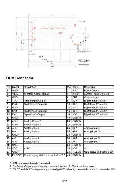
OEM Connector<br />
Pin Signal Description Pin Signal Description<br />
1 GND(1) 2 5V(2) Power Output<br />
3 10µA constant current output 4 200µA constant current output<br />
5 GND(1) 6 CNT Counter Input<br />
7 TRG Trigger Input/Output 8 IO-7 Digital Input/Output 7<br />
9 IO-6 Digital Input/Output 6 10 IO-5 Digital Input/Output 5<br />
11 GND(1) 12 IO-4 Digital Input/Output 4<br />
13 IO-3 Digital Input/Output 3 14 IO-2 Digital Input/Output 2<br />
15 IO-1 Digital Input/Output 1 16 IO-0 Digital Input/Output 0<br />
17 GND(1) 18 GND(1)<br />
19 AO-1 Analog Output 1 20 GND(1)<br />
21 AO-0 Analog Output 0 22 GND(1)<br />
23 AI-6 Analog input 6 24 AI-7 Analog input 7<br />
25 AI-4 Analog input 4 26 AI-5 Analog input 5<br />
27 GND(1) 28 GND(1)<br />
29 AI-2 Analog input 2 30 AI-3 Analog input 3<br />
31 AI-0 Analog input 0 32 AI-1 Analog input 1<br />
33 GND(1) 34 GND(1)<br />
35 VCC +12V 36 VSS -12V<br />
37 GND(1) 38 T-LED(3) USB status and traffic LED<br />
39 P-LED(3) Power supply status and indicator LED 40 GND(1)<br />
1. GND pins are internally connected.<br />
2. 5V Power Outputs are internally connected. A total of 100mA can be sourced.<br />
3. T-LED and P-LED are general purpose digital I/Os directly connected to the microcontroller. With<br />
26/51