DKG-705 AUTOMATIC MAINS FAILURE AND REMOTE START ...
DKG-705 AUTOMATIC MAINS FAILURE AND REMOTE START ...
DKG-705 AUTOMATIC MAINS FAILURE AND REMOTE START ...

You also want an ePaper? Increase the reach of your titles
YUMPU automatically turns print PDFs into web optimized ePapers that Google loves.
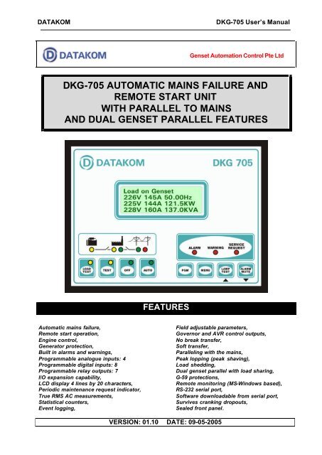
DATAKOM<strong>DKG</strong>-<strong>705</strong> User’s ManualGenset Automation Control Pte Ltd<strong>DKG</strong>-<strong>705</strong> <strong>AUTOMATIC</strong> <strong>MAINS</strong> <strong>FAILURE</strong> <strong>AND</strong><strong>REMOTE</strong> <strong>START</strong> UNITWITH PARALLEL TO <strong>MAINS</strong><strong>AND</strong> DUAL GENSET PARALLEL FEATURESFEATURESAutomatic mains failure,Remote start operation,Engine control,Generator protection,Built in alarms and warnings,Programmable analogue inputs: 4Programmable digital inputs: 8Programmable relay outputs: 7I/O expansion capability,LCD display 4 lines by 20 characters,Periodic maintenance request indicator,True RMS AC measurements,Statistical counters,Event logging,Field adjustable parameters,Governor and AVR control outputs,No break transfer,Soft transfer,Paralleling with the mains,Peak lopping (peak shaving),Load shedding,Dual genset parallel with load sharing,G-59 protections,Remote monitoring (MS-Windows based),RS-232 serial port,Software downloadable from serial port,Survives cranking dropouts,Sealed front panel.VERSION: 01.10 DATE: 09-05-2005
DATAKOM<strong>DKG</strong>-<strong>705</strong> User’s ManualTABLE OF CONTENTSSection1. INSTALLATION1.1. Introduction to the Control Panel1.2. Mounting the Unit1.3. Wiring the Unit2. INPUTS <strong>AND</strong> OUTPUTS3. DISPLAYS3.1. Led Displays3.2. Digital Display3.3. Service Request Display4. ALARMS4.1. Shutdown Alarms4.2. Load Dump Alarms4.3. Warnings5. MODES OF OPERATION5.1. External switching of the operation mode5.2. Remote start operation6. SYNCHRONIZING WITH <strong>MAINS</strong>6.1 Governor Control6.2. AVR Control7. LOAD TRANSFER MODES7.1 Transfer with Interruption7.2 No Break Transfer7.3 Soft Transfer8. PARALLELING WITH <strong>MAINS</strong>: PEAK LOPPING9. DUAL GENSET PARALLEL OPERATION10. PROTECTION FUNCTIONS FOR PARALLEL WITH <strong>MAINS</strong>11. LOAD SHEDDING / DUMMY LOAD12. WEEKLY OPERATION SCHEDULE13. EVENT LOGGING14. STATISTICAL COUNTERS15. MAINTENANCE16. SOFTWARE DOWNLOAD17. PROGRAMMING18. TROUBLESHOOTING19. DECLARATION OF CONFORMITY20. TECHNICAL SPECIFICATIONS21. CONNECTION DIAGRAM<strong>705</strong>-UE.doc - 2 -
DATAKOM<strong>DKG</strong>-<strong>705</strong> User’s Manual1. INSTALLATION1.1 Introduction to the Control PanelThe <strong>DKG</strong>-<strong>705</strong> is a control and protection unit used in gensets. The 4 lines by 20 characters LCDdisplay allows the visualization of many measured parameters. The unit is designed to provide userfriendliness for both the installer and the user. Programming is usually unnecessary, as the factory settingshave been carefully selected to fit most applications. However programmable parameters allow thecomplete control over the generating set. Programmed parameters are stored in a Non Volatile Memoryand thus all information is retained even in the event of complete loss of power.The measurable parameters are:Mains voltage phase R to neutralMains voltage phase S to neutralMains voltage phase T to neutralMains voltage phase R-SMains voltage phase S-TMains voltage phase T-RMains current phase R (optional)Mains current phase S (optional)Mains current phase T (optional)Mains frequencyMains KW phase R (optional)Mains KW phase S (optional)Mains KW phase T (optional)Mains KVA phase R (optional)Mains KVA phase S (optional)Mains KVA phase T (optional)Mains KVAr phase R (optional)Mains KVAr phase S (optional)Mains KVAr phase T (optional)Mains cos? phase R (optional)Mains cos? phase S (optional)Mains cos? phase T (optional)Mains total KW (optional)Mains total KVA (optional)Mains total KVAr (optional)Mains total cos? (optional)Gen voltage phase U to neutralGen voltage phase V to neutralGen voltage phase W to neutralGen voltage phase U-VGen voltage phase V-WGen voltage phase W-UGen current phase UGen current phase VGen current phase WGen frequencyGen KW phase UGen KW phase VGen KW phase WGen KVA phase UGen KVA phase VGen KVA phase WGen KVAr phase UGen KVAr phase VGen KVAr phase WGen cos? phase UGen cos? phase VGen cos? phase WGen total KWGen total KVAGen total KVArGen total cos?Synchronoscope phase angleVoltage match U-RBattery voltage,Engine RPMCoolant temperatureOil pressureOil temperatureFuel level<strong>705</strong>-UE.doc - 3 -
DATAKOM<strong>DKG</strong>-<strong>705</strong> User’s Manual1.2 Mounting the UnitThe unit is designed for panel mounting. The user should not be able to access parts of the unitother than the front panel.Mount the unit on a flat, vertical surface. The unit fits into a standard panel meter opening of 188x140millimeters. Before mounting, remove retaining steel springs from the unit, then pass the unit through themounting opening. The unit will be maintained in its position by the steel springs.The <strong>DKG</strong>-<strong>705</strong> is factory set for 24V-DC operation. If the unit is used in a 12V-DC system, the 12Vjumper terminals must be short-circuited.Do not operate a 12V-DC unit with a 24V-DC system. Thismay cause the destruction of the unit. Always disconnectthe voltage selector jumper of a stocked unit.The engine body must be grounded for correct operation of the unit. Otherwise incorrect voltage andfrequency measurements may occur, resulting in faulty operation of the genset.The output of the current transformers shall be 5 Amperes. The input current rating of the currenttransformers may be selected as needed (between 50/5 and 2500/5 amps). Current transformer outputs shallbe connected by separate cable pairs from each transformer, to related <strong>DKG</strong>-<strong>705</strong> inputs. Never use commonterminals or grounding. The power rating of the transformer should be at least 5 Watts. It is recommended touse 1% precision transformers.If analogue sensors (e.g. temperature, oil pressure, oil temperature or fuel level) are connected to<strong>DKG</strong>-<strong>705</strong>, it is not possible to use auxiliary displays. If temperature or oil pressure displays are already presenton the generator control panel, do not connect the sensors to the <strong>DKG</strong>-<strong>705</strong>. The unit is factory programmedfor VDO type sensors. However if a different type of sensor is to be used, it is possible to recalibrate the unit.The calibration process will be explained later in this document.The programmable digital inputs are compatible with both ‘normally open’ and ‘normally closed’contacts, switching either to BAT- or BAT+.The charge alternator connection terminal provides also the excitation current, thus it is not necessaryto use an external charge lamp.<strong>705</strong>-UE.doc - 4 -
DATAKOM<strong>DKG</strong>-<strong>705</strong> User’s Manual2. INPUTS <strong>AND</strong> OUTPUTS12V JUMPER: When this jumper is placed, 12V-DC operation is selected. Do not operate a 12V-DC unit witha 24V-DC system. This may cause the destruction of the unit. Always disconnect the voltage selector jumperof a stocked unit.RS-232 SERIAL PORT: This connector provides serial data input and output for various purposes likesoftware update, remote monitoring, remote control, remote programming, etc.EXTENSION CONNECTOR (OPTIONAL): This connector is intended for the connection of input and outputextension modules. The optional relay extension module provides 8 programmable 16A relay outputs. The<strong>DKG</strong>-<strong>705</strong> allows the use of up to 2 I/O extension modules.Term Function Technical data Description1 GENERATOR CONTACTOR Relay output, 10A-AC This output provides energy to the generatorcontactor. If the generator phases do not haveacceptable voltage or frequency values, thegenerator contactor will be de-energized. Instandard genset applications, in order toprovide extra security, the normally closedcontact of the mains contactor should beserially connected to this output. In ‘no breaktransfer’ or ‘parallel with mains’applications, this output will drive directly thegenerator contactor.2 UGenerator phase Connect the generator phases to these inputs.3 Vinputs, 0-300V-AC The generator phase voltages upper and4 Wlower limits are programmable.5 GENERATOR NEUTRAL Input, 0-300V-AC Neutral terminal for the generator phases.6 <strong>MAINS</strong> NEUTRAL Input, 0-300V-AC Neutral terminal for the mains phases.7 TMains phase inputs, Connect the mains phases to these inputs.8 S0-300V-ACThe mains voltages upper and lower limits are9 Rprogrammable.10 <strong>MAINS</strong> CONTACTOR Relay output, 10A-AC This output provides energy to the mainscontactor. If the mains phases do not haveacceptable voltage or frequency values, themains contactor will be de-energized. Instandard genset applications, in order toprovide extra security, the normally closedcontact of the generator contactor should beserially connected to this output. In ‘no breaktransfer’ or ‘parallel with mains’applications, this output will drive directly themains contactor.<strong>705</strong>-UE.doc - 6 -
DATAKOM<strong>DKG</strong>-<strong>705</strong> User’s ManualTerm Function Technical data Description11 CURR_W+Current transformer12 CURR_W-inputs, 5A-AC13 CURR_V+14 CURR_V-15 CURR_U+16 CURR_U-Connect the generator current transformerterminals to these inputs. Do not connect thesame current transformer to other units than<strong>DKG</strong>-<strong>705</strong> otherwise a unit fault will occur.Connect each terminal of the transformer tothe unit’s related terminal. Do not usecommon terminals. Do not use grounding.Correct polarity of connection is vital. If themeasured power is negative, then change thepolarity of each 3 current transformers. Therating of the transformers should be the samefor each of the 3 phases. The secondarywinding rating shall be 5 Amperes. (For ex.200/5 Amps).17 HIGH TEMP. SENSOR Input, 0-5000 ohms Analogue high temperature sensorconnection. Do not connect the sensor toother devices.18 OIL PRESSURE SENSOR Input, 0-5000 ohms Analogue oil pressure sensor connection. Donot connect the sensor to other devices.19 FUEL LEVEL SENSOR Input, 0-5000 ohms Analogue fuel level sensor connection. Do notconnect the sensor to other devices.20 OIL TEMP. SENSOR Input, 0-5000 ohms Analogue oil temperature sensor connection.Do not connect the sensor to other devices.Term Function Technical data Description21 PROGRAM LOCK Digital input This input is used to prevent unwantedmodification to programmed values. If thisinput is left open, program values can bemodified via the front panel buttons, but if thisinput is connected to battery- it will not bepossible to change the program values.22 DIGITAL INPUT-723 DIGITAL INPUT-624 DIGITAL INPUT-525 DIGITAL INPUT-426 DIGITAL INPUT-327 DIGITAL INPUT-228 DIGITAL INPUT-129 DIGITAL INPUT-0Digital inputsThese inputs have programmable functions,selectable from a list via the program menu.Each input may be driven by a ‘normallyclosed’ or ‘normally open’ contact, switchingeither battery+ or battery-. The effect of theswitch is also selectable from a list. SeePROGRAMMING section for more details.<strong>705</strong>-UE.doc - 7 -
DATAKOM<strong>DKG</strong>-<strong>705</strong> User’s ManualTerm Function Technical data Description30 GROUND O VDC Power supply negative connection.31 CHARGE Input and output Connect the charge alternator’s D+ terminalto this terminal. This terminal will supply theexcitation current and measure the voltage ofthe charge alternator.32 RELAY-6 (FUEL RELAY) Output 10A/28VDC This relay is normally used for fuel solenoidcontrol. It is internally connected to terminal 31for supplying the charge alternator’s excitationcurrent.33 RELAY-2 (CRANK RELAY) Output 10A/28VDC This relay has programmable function,selectable from a list. However it is generallyused as engine crank output.34 BATTERY POSITIVE +12 or 24VDC The positive terminal of the DC Supply shallbe connected to this terminal. The unitoperates on both 12V and 24V batterysystems, depending on the voltage selectionjumper. Do not operate a 12V-DC unit with a24V-DC system. This may cause thedestruction of the unit. Always disconnectthe voltage selector jumper of a stocked unit.35 RELAY-7 (STOP RELAY) Output 10A/28VDC36 RELAY-1 (PREHEAT) Output 10A/28VDC37 RELAY-3 (ALARM RELAY) Output 10A/28VDCThese relays have programmable functions,selectable from a list.Term Function Technical data Description38 CURR_R+Current transformer Connect the mains current transformer39 CURR_R-inputs, 5A-AC terminals to these inputs. Do not connect the40 CURR_S+same current transformer to other units than41 CURR_S-<strong>DKG</strong>-<strong>705</strong> otherwise a unit fault will occur.42 CURR_T+Connect each terminal of the transformer to43 CURR_T-the unit’s related terminal. Do not usecommon terminals. Do not use grounding.Correct polarity of connection is vital. If themeasured power is negative, then change thepolarity of each 3 current transformers. Therating of the transformers should be the samefor each of the 3 phases. The secondarywinding rating shall be 5 Amperes. (For ex.200/5 Amps).Term Function Technical data Description44 MAGNETIC PICKUP Inputs, 0.5-70V Connect the magnetic pickup signal to these45 MAGNETIC PICKUP 0-20KHzinputs.46 AVR CONTROLOutput,AVR voltage control outputs. Connect to the47 AVR CONTROLisolated resistor,300-1500 ohms.external adjust potentiometer terminals of theAVR. The polarity is not important.48 GOVERNOR CONTROL Output, 0-10VDC Connect this output to the terminal ‘J’ of thespeed governor.<strong>705</strong>-UE.doc - 8 -
DATAKOM<strong>DKG</strong>-<strong>705</strong> User’s Manual3. DISPLAY3.1 Led DisplaysThe <strong>DKG</strong>-<strong>705</strong> has 12 leds, divided in 3 groups:-Group_1: Operating mode: This group indicates the genset function.-Group_2: Mimic diagram: This group indicates the current status of the mains and gensetvoltages and contactors.-Group_3: Warnings and alarms: This group indicates the existency of abnormal conditionsencountered during operation.Function Color Description<strong>MAINS</strong> ON Green The LED will turn on when all 3 mains phase voltagesand the mains frequency are within the limits.<strong>MAINS</strong> OFF Red The LED will turn on when at least one of the mainsphase voltages or the mains frequency are outsidelimits.GENERATOR Yellow The LED will turn on when all 3 generator phasevoltages are within the programmed limits.LOAD GENERATOR Yellow It turns on when the generator contactor is activated.LOAD <strong>MAINS</strong> Green It turns on when the mains contactor is activated.LOAD TESTYellowIt turns on when the related operation mode isTESTYellowselected. One of these LEDs is always on andOFFGreenindicates which operation mode is selected.AUTOGreenIf the operation of the genset is disabled by theweekly operation schedule, then the AUTO led willflash.ALARM Red It turns on when an engine shutdown or load_dumpcondition is occurred.WARNING Red It turns on when an engine shutdown or load_dumpor warning condition is occurred.SERVICE REQUEST Red Engine periodic maintenance request indicator. Itturns on when the preset engine hours or timeduration after previous service has elapsed.<strong>705</strong>-UE.doc - 9 -
DATAKOM<strong>DKG</strong>-<strong>705</strong> User’s Manual3.2 Digital DisplayThe digital display is of LCD type, with 4 lines by 20 characters.It shows:-The software version and release date,-The genset status,-Measured parameters,-Alarm information,-Date and time,-Service counters,-Statistical counters,-Logged events,-Program parameters.During power on, the display shows the software version and the release date for 1 seconds.The display has basically two modes:-Normal operation,-Programming mode.The programming mode will be explained later in this document.The display is driven by a menu system. The display has many different screens, divided into 3main groups.The navigation between different screens in a group is made with the MENU button. Holding theMENU button pressed for 1 second makes the display to switch to the next group.During operation, the <strong>DKG</strong>-<strong>705</strong> will switch automatically between different screens, displayingeach time the most important screen for the given situation.If an alarm or warning occurs during operation other then programming mode, the display willautomatically switch to ALARM LIST position. The MENU button will not allow to switch to other modes.To enable display navigation, press ALARM MUTE button.The display has a backlight illumination feature. The backlight turns on with the depression ofany button. It turns off after 1 minute to allow power economy. Also note that the backlight will turn offduring engine cranking.Group Screen DescriptionContents1 1 Mains parameters Genset statusVoltage R (or RS), current R, Mains FrequencyVoltage S (or ST), current SVoltage T (or TR), current T1 2 Mains parameters Genset statusVoltage RS (or R), current R, Mains FrequencyVoltage ST (or S), current SVoltage TR (or T), current T1 3 Basic genset parameters Genset statusVoltage U (or UV), current U, Genset FrequencyVoltage V (or VW), current V, Genset Active Power (KW)Voltage W (or WU), current W, Genset Power Factor (cos? )1 4 Basic genset parameters Genset statusVoltage UV (or U), current U, Genset FrequencyVoltage VW (or V), current V, Genset Active Power (KW)Voltage WU (or W), current W, Genset Power Factor (cos? )<strong>705</strong>-UE.doc - 10 -
DATAKOM<strong>DKG</strong>-<strong>705</strong> User’s ManualGroup Screen DescriptionContents1 5 Engine parameters Engine rpm, Battery VoltageCoolant Temperature, Fuel LevelOil Temperature, Oil Pressure1 6 Genset power Genset Active Power (KW) , Genset FrequencyGenset Apparent Power (KVA), Genset Power Factor(cos? )Genset Reactive Power (KWr)1 6 Alarm list If no alarm exists this screen will display ‘END OF ALARMLIST’. Existing alarms, load_dumps and warnings will bedisplayed as one screen for each entry. Switching to thenext entry will be made with the MENU button.Group Screen DescriptionContents2 1 Genset phase U parameters Phase to Neutral Voltage, Phase Active Power (KW)Phase Current , Phase Apparent Power (KVA)Phase Power Factor, Phase Reactive Power (KWr)2 2 Genset phase V parameters Phase to Neutral Voltage, Phase Active Power (KW)Phase Current , Phase Apparent Power (KVA)Phase Power Factor, Phase Reactive Power (KWr)2 3 Genset phase W parameters Phase to Neutral Voltage, Phase Active Power (KW)Phase Current , Phase Apparent Power (KVA)Phase Power Factor, Phase Reactive Power (KWr)2 4 Synchronoscope Governor Output (%)I AVR Output(%)Voltage RU,Phase Angle (degrees)Phase U Voltage, Genset FrequencyPhase R Voltage, Mains Frequency2 5 Soft transfer parameters Remaining DurationGovernor Output (%), AVR Output(%)Genset Active Power (KW), Gen. Reactive Power (KWr)Target Active Power (KW), Target React. Power (KWr)2 6 Date, time, engine hours Date, TimeEngine Hours Run2 7 Service display Time to ServiceEngine Hours to Service2 8 Total power counters Total Genset Active Power (KW-h)Total Genset Apparent Power (KVA-h)Total Genset Reactive Power (KWr-h)2 9 Statistical counters Total Engine CranksTotal Genset RunsTotal Genset on Load2 10 Mains phase R parameters Phase to Neutral Voltage, Phase Active Power (KW)Phase Current , Phase Apparent Power (KVA)Phase Power Factor, Phase Reactive Power (KWr)2 11 Mains phase S parameters Phase to Neutral Voltage, Phase Active Power (KW)Phase Current , Phase Apparent Power (KVA)Phase Power Factor, Phase Reactive Power (KWr)2 12 Mains phase T parameters Phase to Neutral Voltage, Phase Active Power (KW)Phase Current , Phase Apparent Power (KVA)Phase Power Factor, Phase Reactive Power (KWr)Group Screen Description Contents3 1…32 Event logging This group comprises 32 screens, each screendisplaying one recorded event, starting from the mostrecent one.<strong>705</strong>-UE.doc - 11 -
DATAKOM<strong>DKG</strong>-<strong>705</strong> User’s Manual3.3 Service Request DisplayThis led is designed to help the periodic maintenance of the genset to be made consistently.The periodic maintenance is basically carried out after a given engine hours (for example 200 hours),but even if this amount of engine hours is not fulfilled, it is performed after a given time limit (for example 365days).The SERVICE REQUEST led has no effect on the gensetoperation.The <strong>DKG</strong>-<strong>705</strong> has both programmable engine hours and maintenance time limit. The engine hours isprogrammable between 0 and 2500 hours with 10-hour steps (P_624), the time limit is programmable between0 and 2500 days with 10 day steps (P_625). If any of the programmed values is zero, this means that theparameter will not be used. For example a maintenance period of 0 days indicates that the <strong>DKG</strong>-<strong>705</strong> willrequest maintenance only based on engine hours. There will be no time limit. If the engine hours is alsoselected as 0 hours this will mean that the SERVICE REQUEST display will be inoperative.The remaining engine hours and the remaining time limit are kept stored in a non-volatile memory andare not modified by power supply failures. The remaining engine hours and time to service may be checked onthe LCD display. (group_2, screen_7)When the engine hours OR the time limit is over, the SERVICE REQUEST led (red) will start to flash.To turn off the led, select programming mode, enter factory password and set the parameter_600 to 1, thencheck the remaining time and engine hours to service using group_2, screen_7.<strong>705</strong>-UE.doc - 12 -
DATAKOM<strong>DKG</strong>-<strong>705</strong> User’s Manual4. ALARMSAlarms indicate an abnormal situation in the generating set.The alarms are divided into 3 priority level:1- SHUTDOWN ALARMS: These are the most important alarm conditions and cause:- The genset contactor to be released immediately,- The engine to be stopped immediately,- The alarm relay output to operate,- The ALARM led to turn on,- The LCD display to switch to alarm display mode (except when programming).2- LOAD DUMP ALARMS: These conditions cause:- The genset contactor to be released immediately,- The engine to be stopped after the cooldown cycle,- The alarm relay output to operate,- The ALARM led to turn on,- The LCD display to switch to alarm display mode (except when programming)3- WARNINGS: These conditions cause:- The alarm relay output to operate,- The WARNING led to turn on.Most of the alarms are of LATCHING type. Even is the alarm condition is removed, the alarms will stayon and disable the operation of the genset.The existing alarms may be canceled by pressing one of the operating mode buttons (LOAD TEST /TEST / OFF / AUTO) or by pressing the ALARM MUTE button twice.If the ALARM MUTE button is pressed, the alarm relay output will be deactivated; however theexisting alarms will persist and disable the operation of the genset.limits.Most of the alarms have programmable trip levels. See the programming chapter for settable alarmThe digital inputs are programmable and may be set to provide a large variety of alarms and warnings.See the programming chapter for digital input programming.The alarms may be cancelled either by pressing any of the front panel mode selection buttons or by achange in external mode force inputs.<strong>705</strong>-UE.doc - 13 -
DATAKOM<strong>DKG</strong>-<strong>705</strong> User’s Manual4.1 Shutdown AlarmsDefinition Source DescriptionLow Oil Pressure Switch Digital Input These shutdown alarms are set depending on the digital inputHigh Eng.Temp.Switch Digital Input settings. The related program parameters are P_700 to P_776.Emergency Stop Digital InputLow Coolant Level Digital InputAlternator High Temp. Digital InputHigh Oil Temp. Digital InputOverloadDigital InputLow Fuel Level Digital InputBattery Charger Fail Digital InputSpare Alarm 7Digital InputSpare Alarm 6Digital InputSpare Alarm 5Digital InputSpare Alarm 4Digital InputSpare Alarm 3Digital InputSpare Alarm 2Digital InputSpare Alarm 1Digital InputGen Under-Frequency Phase U Set if the genset frequency goes under the Low FrequencyShutdown (P_516) limit for Frequency Timer (P_520) period.Gen Over Frequency Phase U Set if the genset frequency goes over the High FrequencyShutdown (P_518) limit for Frequency Timer (P_520) period.High Battery Voltage Battery Set if the battery voltage goes over the High Battery VoltageShutdown (P_610) limit.Low Fuel Level Analog In. Set if the fuel level measured from analog input goes under the LowFuel Level Shutdown (P_608) limit.High Oil Temperature Analog In. Set if the oil temperature measured from analog input goes over theHigh Oil Temperature Shutdown (P_606) limit.High CoolantTemperatureAnalog In. Set if the coolant temperature measured from analog input goesover the High Coolant Temperature Shutdown (P_604) limit.Low Oil PressureMeasuredAnalog In. Set if the oil pressure measured from analog input goes under theLow Oil Pressure Shutdown (P_602) limit.Fail To Stop Internal Set if the engine is not stopped before the expiration of the StopTimer (P_505).Fail To Start Internal Set if the has not started after Start Attempts (P_504) number ofattempts.Genset Low Voltage U-V-W Set if any of the genset phase voltages goes under the GeneratorLow Limit (P_514) voltage.Genset High Voltage U-V-W Set if any of the genset phase voltages goes over the GeneratorHigh Limit (P_515) voltage.Slave Unavailable (dualgenset mode)SerialComm.Set if a shutdown or load dump alarm has occurred in the slavegenset and Single Genset Load Enable parameter (P_A32) is setto 0.Gen Phase SequenceFailLow Engine SpeedHigh Engine SpeedCommunication Lost(dual genset mode)U-V-WMagneticPickupMagneticPickupSerialComm.Set if the generator phase sequence is not correct. This alarm maybe cancelled also by programming the Ignore Phase Orderparameter (P_A06) to 1.Set if the engine rpm goes under the Low rpm Shutdown (P_613)limit. If the Crank Teeth Count (P_619) is set to ‘0’, this alarm willbe disabled.Set if the engine rpm goes over the High rpm Shutdown (P_615)limit. If the Crank Teeth Count (P_619) is set to ‘0’, this alarm willbe disabled.Set if the serial communication between Master and Slave gensetsis interrupted and Single Genset Load Enable parameter (P_A32)is set to 0.<strong>705</strong>-UE.doc - 14 -
DATAKOM<strong>DKG</strong>-<strong>705</strong> User’s Manual4.2 Load Dump AlarmsDefinition Source DescriptionLow Oil Press.Switch Digital Input These load dump alarms are set depending on the digital inputHigh Eng.Temp.Switch Digital Input settings. The related program parameters are P_700 to P_776.Emergency Stop Digital InputLow Coolant Level Digital InputAlternator High Temp. Digital InputHigh Oil Temp. Digital InputOverloadDigital InputLow Fuel Level Digital InputBattery Charger Fail Digital InputSpare Alarm 7Digital InputSpare Alarm 6Digital InputSpare Alarm 5Digital InputSpare Alarm 4Digital InputSpare Alarm 3Digital InputSpare Alarm 2Digital InputSpare Alarm 1Digital InputGen Reverse Power Internal Set if the genset consumes active power (KW) from the mains andthis power goes over the Reverse Power Load Dump (P_618)limit.Gen Excess Power Internal Set if the genset power (KW) supplied to the load goes over theExcess Power Load Dump (P_617) limit for Overcurrent / ExcessPower Timer (P_511).Alternator Overcurrent Internal Set if at least one of the genset phase currents goes over theOvercurrent Limit (P_510) for Overcurrent / Excess PowerTimer (P_511).<strong>705</strong>-UE.doc - 15 -
DATAKOM<strong>DKG</strong>-<strong>705</strong> User’s Manual4.3 WarningsDefinition Source DescriptionLow Oil Press.Switch Digital Input These warnings are set depending on the digital input settings. TheHigh Eng.Temp.Switch Digital Input related program parameters are P_700 to P_776.Emergency Stop Digital InputLow Coolant Level Digital InputAlternator High Temp. Digital InputHigh Oil Temp. Digital InputOverloadDigital InputLow Fuel Level Digital InputBattery Charger Fail Digital InputSpare Alarm 7Digital InputSpare Alarm 6Digital InputSpare Alarm 5Digital InputSpare Alarm 4Digital InputSpare Alarm 3Digital InputSpare Alarm 2Digital InputSpare Alarm 1Digital InputSynchronization Fail Internal Set if the phase and voltage synchronization is not successfulbefore the expiration of Synchronization Fail Timeout (P_A07).Gen Under-Frequency Phase-U Set if the genset frequency goes under the Low FrequencyWarning (P_517) limit for Frequency Timer (P_520) period.Gen Over-Frequency Phase-U Set if the genset frequency goes over the High FrequencyWarning (P_519) limit for Frequency Timer (P_520) period.High Battery Voltage Internal Set if the battery voltage goes over the High Battery VoltageWarning (P_611) limit.Low Fuel Level AnalogInputSet if the fuel level measured from analog input goes under the LowFuel Level Warning (P_609) limit.High Oil Temperature AnalogInputSet if the oil temperature measured from analog input goes over theHigh Oil Temperature Warning (P_607) limit.High CoolantTemperatureAnalogInputSet if the coolant temperature measured from analog input goesover the High Coolant Temperature Warning (P_605) limit.Low Oil PressureMeasuredAnalogInputSet if the oil pressure measured from analog input goes under theLow Oil Pressure Warning (P_603) limit.Mains Phase SequenceFailR-S-T Set if the mains phase sequence is not correct and Ignore PhaseOrder (P_A06) parameter is ‘0’.Charge Failure ChargeinputSet if the Charge input (terminal_31) is pulled to battery negativewhen the engine is running.Low Battery Voltage Internal Set if the battery voltage goes under the Low Battery VoltageWarning (P_612) limit.AVR Control Fail Internal Set if the AVR control output has gone to the low or high limitvalue for 1 second.GOV Control Fail Internal Set if the GOV control output has gone to the low or high limitvalue for 1 second.Low Engine Speed MagneticPickupSet if the engine rpm goes under the Low rpm Warning (P_614)limit. If the Crank Teeth Count (P_619) is set to ‘0’, this warning willHigh Engine SpeedMagneticPickupbe disabled.Set if the engine rpm goes over the High rpm Warning (P_616)limit. If the Crank Teeth Count (P_619) is set to ‘0’, this warning willbe disabled.<strong>705</strong>-UE.doc - 16 -
DATAKOM<strong>DKG</strong>-<strong>705</strong> User’s ManualDefinition Source DescriptionParallel Mains Fail Internal This general warning is set if any of the protection functions havedetected a mains failure during parallel with mains operation.Mains Reverse Power Internal In parallel with mains operation and after the parallel checktimeout delay (P_A23) has elapsed, this warning will be set if themains power is negative and over the reverse power limit defined inP_A24.Mains Frequency Fail R In parallel with mains operation and after the parallel check timeoutdelay (P_A23) has elapsed, this warning will be set if the mainsfrequency is out of the limits defined in P_522 and P_523 for 4consecutive cycles.No Mains Frequency R In parallel with mains operation and after the parallel check timeoutdelay (P_A23) has elapsed, this warning will be set if the mainsfrequency disappears for more than 2,5 periods.ROCOF (df/dt) Fail R In parallel with mains operation and after the parallel check timeoutdelay (P_A23) has elapsed, this warning will be set if the mainsfrequency change exceeds the limit defined in P_A25 for 4consecutive cycles.Vector Shift (df/dt) Fail R In parallel with mains operation and after the parallel check timeoutdelay (P_A23) has elapsed, this warning will be set if the phase ofthe mains measured on last 2 cycles jumps over the limit definedin P_A26 on the phase measured on last 4 th and 5 th period.Communication Lost(dual genset mode)SerialComm.Set if the serial communication between Master and Slave gensetsis interrupted and Single Genset Load Enable parameter (P_A32)is set to 1.<strong>705</strong>-UE.doc - 17 -
DATAKOM<strong>DKG</strong>-<strong>705</strong> User’s Manual5. MODES OF OPERATIONThe modes of operation are selected either by pushing the front panel keys or using the external modeselect inputs. External inputs override the front panel selection. If none of the external inputs is active, the unitresumes to the mode selected by the front panel. Following selected mode, the <strong>DKG</strong>-<strong>705</strong> will have differentbehavior.OFF: In this mode, the mains contactor will be energized if mains phase voltages and frequency are within theprogrammed limits. The engine will be stopped.AUTO: It is used for genset and mains automatic transfer. If at least one of the mains phase voltages or themains frequency is outside limits, the mains contactor will be deactivated.The diesel will be started for programmed times after the wait period. When the engine runs, the crank relaywill be immediately deactivated. The engine will run without load during engine heating period. After this, ifalternator phase voltages and frequency are within limits, the unit will wait for the generator contactor periodand the generator contactor will be energized.When all the mains phase voltages and the mains frequency is within the limits, the engine will continue to runfor the mains waiting period. At the end of this period the generator contactor is deactivated and the mainscontactor will be energized. If a cooling period is given, the generator will continue to run during cooling period.At the end of the period, the fuel solenoid will be de-energized and the diesel will stop. The unit will be readyfor the next mains failure.If the operation of the genset is disabled by the weekly schedule, then the AUTO led will flash, and theoperation of the genset will be as in the OFF mode.LOAD TEST: It is used to test the genset under load. Once this mode is selected, the engine will run and theload will be transferred to the genset. The genset will feed the load indefinitely unless another mode isselected.TEST: It is used to test the generator when the mains are on, or keep the generator waiting in the emergencybackup mode. The operation of the generator is similar to the AUTO mode, but the mains contactor will not bedeactivated if the mains are not off. If the mains are off, mains contactor will be deactivated and the generatorcontactor will be activated. When the mains are on again, a changeover to the mains will be made, but theengine will be kept running unless another mode is selected. The emergency backup operation may beprohibited using the program parameter P_629.5.1 External Switching of the Operation ModeThe Mode of operation of the unit may also be selected by external inputs instead of front panel keys.For this, at least one of the digital inputs should be programmed as an input to force one of the 4 operatingmodes. The corresponding input’s P_7x0 parameter should be set to 18, 19, 20 or 21. The mode selectionsignal may be a NO or NC contact, switching to either battery positive or battery negative. These selectionsare made using parameters P_7x5 and P_7x6.The external selection input has a higher level of priority than the front panel keys. Thus if theoperating mode is forced by the external input, this will override the selection made by the front panel keys.However, when the external selection signal goes off, the unit will resume to the mode selected by the frontpanel keys.If a front panel mode selection key is pressed while the external mode select input is active, then thekey selection will be stored and when the external selection signal goes off, the unit will resume to this mode.<strong>705</strong>-UE.doc - 18 -
DATAKOM<strong>DKG</strong>-<strong>705</strong> User’s Manual5.2. Remote Start OperationThe unit offers the possibility of <strong>REMOTE</strong> <strong>START</strong> mode of operation. In this mode the mainsphases are not monitored. If the <strong>REMOTE</strong> <strong>START</strong> signal is present then the mains will be supposed to fail,inversely if the <strong>REMOTE</strong> <strong>START</strong> signal is absent, then mains voltages will be supposed to be present. Thefront panel mimic diagram’s mains LEDs will reflect the status of the <strong>REMOTE</strong> <strong>START</strong> input.Any of the digital inputs may be programmed as a <strong>REMOTE</strong> <strong>START</strong> input. For this thecorresponding input’s P_7x0 parameter should be set to 23. The <strong>REMOTE</strong> <strong>START</strong> signal may be a NO or NCcontact, switching to either battery positive or battery negative. These selections are made using parametersP_7x5 and P_7x6.<strong>705</strong>-UE.doc - 19 -
DATAKOM<strong>DKG</strong>-<strong>705</strong> User’s Manual6. SYNCHRONIZING WITH <strong>MAINS</strong>The <strong>DKG</strong>-<strong>705</strong> offers the possibility of synchronizing the genset with the mains.The synchronization comprises frequency, phase and voltage matching features.The synchronization properties of the unit are adjusted with program parameters.These parameters are reserved for factory and qualified installationpersonal use and must not be modified by end users or non-qualifiedservice personal. Otherwise severe damage may occur!6.1 Governor ControlThe frequency and phase matching is made by controlling the engine’s governor module. The<strong>DKG</strong>-<strong>705</strong> compares the mains phase R with the genset phase U. If the engine does not have a speedgovernor it is not possible to make frequency or phase control.The GOV output (terminal 45) is an analog voltage output of 0-10 VDC. The output impedance is180 ohms.The functions of the GOV output are controlled by programmed parameters:P_A02 GOV Control Enable: This parameter enables/disables the activation of the governor controloutput. If governor control is disabled, the output will always stay at the rest level defined by P_A13.P_A03 GOV Reverse Polarity: In normal polarity, the governor control voltage increases in order toincrease the engine speed. If reverse polarity is selected the governor control voltage decreases in order toincrease the engine speed.P_A13 Governor Start: This is the rest value of the governor control output. Always set this value to 128,which is the mid-course, and then adjust the engine speed from the speed governor. However, if needed,engine speed adjustment may be made through this parameter. Do not forget that, if this parameter ismodified, the adjustment range will be reduced.P_A15 Frequency Lock Gain: This parameter defines the reaction speed of the governor output to phasedifferences between genset and mains phases during synchronization. The standard value for thisparameter is 32. But it must be readjusted for the engine during manufacturing. If this parameter is toohigh, a phase oscillation may occur. If it is too low, the phase locking will have a lazy behavior.<strong>705</strong>-UE.doc - 20 -
DATAKOM<strong>DKG</strong>-<strong>705</strong> User’s Manual6.2 AVR ControlThe voltage matching is controlled by the alternator’s AVR module. The <strong>DKG</strong>-<strong>705</strong> compares themains phase R voltage with the genset phase U voltage.The AVR control output (terminals 43-44) is similar to an isolated variable resistor. Usually allbrands and types of AVR accept an external adjustment potentiometer. The AVR control will use theseinputs, thus the <strong>DKG</strong>-<strong>705</strong> is able to control most of the AVRs found on the market.The impedance range of the AVR output is 300 ohms to 200 K-ohms. The range is adjustable withan internal potentiometer accessible from the back panel of the unit.The functions of the AVR output are controlled by programmed parameters:P_A04 AVR Control Enable: This parameter enables/disables the activation of the AVR control output. IfAVR control is disabled, the output will always stay at the rest level defined by P_A14.P_A05 AVR Reverse Polarity: In normal polarity, the AVR control impedance decreases in order toincrease the alternator voltage. If reverse polarity is selected the AVR impedance increases in order toincrease the alternator voltage.P_A14 AVR Start: This is the rest value of the AVR control impedance. Always set this value to 128,which is the mid-course, and then adjust the alternator voltage with the AVR’s control pot. However, ifneeded, alternator voltage adjustment may be made through this parameter. Do not forget that, if thisparameter is modified, the adjustment range will be reduced.P_A16 AVR Gain: This parameter defines the reaction speed of the AVR output to voltage differencesbetween genset and mains phases during synchronization. The standard value for this parameter is 64.But it must be readjusted for the genset during manufacturing. If this parameter is too high, a voltageoscillation may occur. If it is too low, the voltage matching will be slower.<strong>705</strong>-UE.doc - 21 -
DATAKOM<strong>DKG</strong>-<strong>705</strong> User’s Manual7. LOAD TRANSFER MODESversa.The <strong>DKG</strong>-<strong>705</strong> has more than one ways of transferring the load from genset to mains and viceThese modes are:-transfer with interruption,-no break transfer, (with or without synchronization)-soft transfer.7.1 Transfer with InterruptionThis is the most conventional way of transferring the load between the genset and mains. Therewill be a power interruption period duration during the transfer. Note that the program parameters P_508and P_509 define the power interruption period.If this transfer method is used, it is advised to make an electrical interlockbetween the two contactors to prevent a phase to phase short circuit.Transfer from genset to mains:-The generator contactor releases,-The unit waits for Mains Contactor Timer (P_508)-The mains contactor is energized.Transfer from mains to genset:-The mains contactor releases,-The unit waits for Generator Contactor Timer (P_509)-The generator contactor is energized.<strong>705</strong>-UE.doc - 22 -
DATAKOM<strong>DKG</strong>-<strong>705</strong> User’s Manual7.2 No Break TransferIn this mode, the transfer will be made without power interruption. This implies that both of themains and generator contactors will be active during transfer.The maximum duration that both contactors will be active is programmable. However this processmay be quicker with the use of one auxiliary contact at each contactor. Thus the changeover will be quiteinstantaneous, preventing any excess or reverse power condition. Normally the digital input_6 (terminal 23)is used for mains contactor auxiliary contact and the digital input_7 (terminal 22) is used for generatorcontactor auxiliary contact.To prevent a phase to phase short circuit below criteria must be met:-The mains and generator voltages must be equal,-The mains and generator voltages must have the same phase,-The mains and generator voltages must have the same phase sequence order.The <strong>DKG</strong>-<strong>705</strong> will allow a No Break Transfer only if all of the below conditions are fulfilled:-Mains phase voltages within the programmed limits,-Mains frequency within the programmed limits,-Genset phase voltages within the programmed limits,-Genset frequency within the programmed limits,-Mains phase order correct (or phase order check must be disabled),-Genset phase order correct (or phase order check must be disabled),-The difference between mains and genset frequencies not more than programmed limit,-The voltage difference between phase R and phase U not more than programmed limit,-The phase angle between phase R and phase U not more than programmed limit,When a No Break Transfer cycle is initiated, the <strong>DKG</strong>-<strong>705</strong> checks all the above criteria to besatisfied. If any of the checks fail, then the unit reverts to a Transfer with Interruption.If all conditions are met, the unit proceeds to the synchronization. The GOV output, if enabled,acts to equalize the phase between the genset and the mains voltages. The AVR output, if enabled, tendsto equalize the genset and mains voltages.It is also possible to make a No Break Transfer without GOV or AVR control. In this case the unitwill wait until the expiration of the Synchronization Fail Timeout (P_A07), to find a matching phase andvoltage. Normally with frequencies matching at +/- 2Hz and voltages matching at +/-10 volts anuncontrolled No Break Transfer will be successful if auxiliary contacts of the contactors are used. Alsonote that most of the standard AVRs will accept external voltage matching, thus only a rough frequencymatching will be enough to succeed a No Break Transfer.If matching is found before the expiration of the Synchronization Fail Timeout (P_A07), thenboth contactors will be activated. If contactor auxiliary contacts are used, the other contactor will releaseimmediately. If contactor auxiliary contacts are not used, the other contactor will release after contactortimeout (P_A09).<strong>705</strong>-UE.doc - 23 -
DATAKOM<strong>DKG</strong>-<strong>705</strong> User’s ManualThe <strong>DKG</strong>-<strong>705</strong> has a set of programmable parameters to define the No Break Transfer operation.These parameters are:P_512 Mains Low Limit: Each of the mains phase voltages must be over this limit.P_513 Mains High Limit: Each of the mains phase voltages must be below this limit.P_514 Gen Low Limit: Each of the genset phase voltages must be over this limit.P_515 Gen High Limit: Each of the genset phase voltages must be below this limit.P_516 Low Frequency Shutdown: The genset frequency must be over this limit.P_517 Low Frequency Warning: The genset frequency must be over this limit.P_518 High Frequency Shutdown: The genset frequency must be below this limit.P_519 High Frequency Warning: The genset frequency must be below this limit.P_522 Mains Frequency Low Limit: The mains frequency must be over this limit.P_523 Mains Frequency High Limit: The mains frequency must be below this limit.P_A00 No Break Transfer: This parameter enables/disables the No Break Transfer feature.P_A06 Ignore Phase Order: If set, this parameter will disable the phase order check. The phase ordercheck should be disabled only in single phase gensets.P_A07 Synchronization Fail Timeout: If the phase and voltage synchronization is not successful beforethe expiration of this timer, then the <strong>DKG</strong>-<strong>705</strong> renounces the No Break Transfer and makes a Transferwith Interruption.P_A09 Contactor Timeout: This is the maximum time duration in which both contactors are active in caseof No Break Transfer.P_A10 Max Frequency Difference: This is the maximum difference between mains and gensetfrequencies to enable a NO Break Transfer.P_A11 Max Voltage Difference: This is the maximum difference between the mains phase-R and thegenset phase-U voltages to enable a NO Break Transfer.P_A12 Max Phase Difference: This is the maximum phase difference between the mains phase-R andthe genset phase-U to enable a No Break Transfer.P-760 to P_766: These parameters define the function of digital input_6.P-770 to P_776: These parameters define the function of digital input_7.<strong>705</strong>-UE.doc - 24 -
DATAKOM<strong>DKG</strong>-<strong>705</strong> User’s Manual7.3 Soft TransferIn this mode, the transfer will be made without interruption like the No Break Transfer mode. Butthe load will not be transferred suddenly, instead of this it will be gradually transferred under GOV andAVR control.The AVR and GOV control are absolutely necessary to succeed a Soft Transfer.With the basic <strong>DKG</strong>-<strong>705</strong> unit, only a soft transfer from the genset to the mains is possible. Thetransfer from mains to the genset will simply be a No Break Transfer.With a full version of <strong>DKG</strong>-<strong>705</strong> with mains current inputs, soft transfer in both directions areallowed.The Soft Transfer sequence starts like a No Break transfer. But when both contactors areactivated, the unit starts transferring the KW and KVAr load to the mains with predefined ramps. Thisramping is achieved with GOV and AVR control. The duration of the load transfer sequence is controlledby the Soft Transfer Timer (P_A08).The unit includes a comprehensive set of protection functions to detect quickly a mains failureduring parallel with mains operation. The protections are enabled after the timeout defined by theparameter P_A23. These protections will be explained with more detail in the following chapter.If a mains failure occurs during parallel with mains operation, the mains contactor will immediatelydeenergize, a general Parallel Mains Fail warning and a specific protection function warning will begenerated.At the end of the Soft Transfer Timer (P_A08) the generator contactor will be released. If anyalarm is encountered during the Soft Transfer sequence, the <strong>DKG</strong>-<strong>705</strong> will revert to Interrupted transfer.The <strong>DKG</strong>-<strong>705</strong> has a set of programmable parameters to define the Soft Transfer operation. Allparameters used in No Break Transfer are also used in Soft Transfer. Additional parameters are:P_A01 Soft Transfer Enable: This parameter enables/disables the Soft Transfer feature.P_A08 Soft Transfer Timer: This is the time duration of the Soft Transfer. At the end of this timer one ofthe contactors will release to terminate the parallel operation.P_633 Mains Current Transf ormers: This parameter enables/disables the Soft Transfer from Mains toGenset.P_A18 KW Ramp: The load’s active power (KW) will be transferred to the mains with this rate.P_A19 KVAr Ramp: The load’s reactive power (KVAr) will be transferred to the mains with this rate.P_A20 KW Gain: This parameter defines the reaction speed of the KW control during soft transfer.P_A21 KVAr Gain: This parameter defines the reaction speed of the KVAr control during soft transfer.P_A23 Parallel Check Timeout: This is the delay after the mains contactor is energized (for parallel tomains) and before the protections for mains failure are enabled.<strong>705</strong>-UE.doc - 25 -
DATAKOM<strong>DKG</strong>-<strong>705</strong> User’s Manual8. PARALLELING WITH <strong>MAINS</strong>: PEAK LOPPINGThe Peak Lopping feature consists on the use of the genset as a backup to the mains in caseswhere the mains power rating is insufficient to supply the load.The peak lopping application is only possible with slowly varying loads.When peak lopping is enabled and the unit is in AUTO mode, the genset will start and enter inparallel with the mains if mains power exceeds the parameter P_A29 (genset start limit). As the mainspower limit is not exceeded it will not supply power to the load.When the total load power exceeds the parameter P_A28 (mains power limit) the unit will allow themains to deliver only P_A28 (mains power limit) to the load. The exceeding quantity will be supplied by thegenset.When the total load power falls below the parameter P_A30 the generator contactor will releaseand the genset will stop following a cooldown cycle.The parameter P_A30 should be less than the parameter P_A29 in order to prevent immediatestopping of the genset after start.The unit includes a comprehensive set of protection functions to detect quickly a mains failureduring parallel with mains operation. The protections are enabled after the timeout defined by theparameter P_A23. These protections will be explained with more detail in the following chapter.If a mains failure occurs during parallel with mains operation, the mains contactor will immediatelydeenergize, a general Parallel Mains Fail warning and a specific protection function warning will begenerated. The load will be supplied by the genset without interruption. When mains is restored again, thegenset will synchronize with the mains and resume to parallel operation.The <strong>DKG</strong>-<strong>705</strong> has a set of programmable parameters to define the Peak Lopping operation. Allparameters used in No Break Transfer and Soft transfer are also used in Peak Lopping. Additionalparameters are:P_A27 Peak Lopping Enable: This parameter enables/disables the Peak Lopping operation.P_A28 Mains Power Limit: This is maximum active power that the mains may deliver.P_A29 Genset Start Limit: This is the mains active power limit for the start of the genset.P_A30 Genset Stop Limit: This is the total load active power for the stop of the genset.<strong>705</strong>-UE.doc - 26 -
DATAKOM<strong>DKG</strong>-<strong>705</strong> User’s Manual9. DUAL GENSET PARALLEL OPERATIONThe <strong>DKG</strong>-<strong>705</strong> is able to work in Dual Genset Parallel mode without any hardware or softwaremodifications. The only additional accessory needed is a simple RS -232 serial data cable.The units used in paralleling are standard <strong>DKG</strong>-<strong>705</strong>s with standard software, which permits verylow cost synchronization applications.The basic features are:-simple and cost effective application,-adaptation to all kinds of AVR and GOV controllers without extra hardware,-different power ratings acceptable for both gensets,-single genset load enabling,-slave genset run/stop depending on user defined power levels and time delays,-equal aging: automatic master/slave switching depending on ‘Engine Hours to Service’,-automatic master/slave switching in case of failure of the Master unit,-manual master/slave switching allowed,-predefined Master unit without the need for AVR and GOV controls on master,-synchronization with mains: uninterrupted transfer to/from mains,-load share with mains: soft transfer to/from mains.guide.Please refer to the <strong>DKG</strong>-<strong>705</strong> Dual Genset Parallel Application Manual for a detailed application<strong>705</strong>-UE.doc - 27 -
DATAKOM<strong>DKG</strong>-<strong>705</strong> User’s Manual10. PROTECTION FUNCTIONS FOR PARALLEL WITH <strong>MAINS</strong>The dkg-<strong>705</strong> includes a comprehensive set of protection functions to detect quickly a mainsfailure during parallel with mains operation.The protections are enabled after the timeout defined by the parameter P_A23 (Parallel CheckTimeout) in order not to detect a mains failure during transients caused by the closing of the contactors.WARNING: Do not forget that the protections are disabled during ParallelCheck Timeout. Set this timeout as short as possible.If any of the protection functions detects a mains failure during parallel with mains:-the mains contactor is immediately deenergized,-a Parallel Mains Fail warning is generated,-a specific warning to the related protection function is generated.Separating the generator from the mains in case of a mains failure is requested as condition inmost countries for connection of synchronous generators to the mains.10.1 ROCOF FUNCTION (rate of change of frequency)The ROCOF measures the frequency of the mains for each period. If the frequency changeexceeds the predefined limit for 4 successive periods, the ROCOF detects a mains failure. Thus theresponse time of the ROCOF is approximately 4 cycles.However the ROCOF will not detect relatively slow changes in mains frequency.Related parameter: P_A25 ROCOF df/dt Limit:10.2 VECTOR SHIFT FUNCTIONThe Vector Shift measures and stores the periods of last 5 cycles. At the end of each cycle itcompares the average period of last 2 cycles with the average period of 4 th and 5 th cycles. If the differenceexceeds the predefined limit the vector shift detects a mains failure. Thus the response time of the vectorshift is 5 cycles.However the vector shift will not detect relatively slow changes in mains frequency.Related parameter: P_A26 Vector Shift Limit10.3 OVER/UNDER FREQUENCY FUNCTIONThe mains frequency measures the frequency of the mains for each period. If the frequency isoutside limits for 4 successive periods, it detects a mains failure. The response time of the mainsfrequency is approximately 4 cycles.Related parameters:P_522 Mains Frequency Low LimitP_523 Mains Frequency High Limit<strong>705</strong>-UE.doc - 28 -
DATAKOM<strong>DKG</strong>-<strong>705</strong> User’s Manual10.4 OVER/UNDER VOLTAGE FUNCTIONThe mains phase voltages are measured twice a second and compared with predefined high andlow limits. If at least one of the phase voltages is outside limits, this will mean a mains failure. Theresponse time is approximately 500ms.Related parameters:P_512 Mains Voltage Low LimitP_513 Mains Voltage High Limit10.5 <strong>MAINS</strong> REVERSE POWER FUNCTIONThe mains active power is measured for each period. If the genset supplies power to mains andthis power exceeds the predefined limit this will mean a mains failure.The mains reverse power detector has a variable response time. For a power not exceeding 2times the predefined limit the response time is 8 cycles. The response time is reduced with larger reversepowers. It is approximately 1 cycle with a reverse power of 8 times the predefined limit.If mains current transformers are not fitted, the mains reverse power protection will not operate.Thus a full version of <strong>DKG</strong>-<strong>705</strong> is required for this protection.Related parameters:P_633 Mains Current TransformersP_A24 Reverse Power Limit10.6 NO FREQUENCY FUNCTIONThe unit counts the time after the last detection of the mains frequency pulses. If no mainspulses is detected for a period corresponding to 2,5 times the Mains Frequency Low Limit (P_522), amains failure alarm is generated.Related parameter:P_522 Mains Frequency Low Limit<strong>705</strong>-UE.doc - 29 -
DATAKOM<strong>DKG</strong>-<strong>705</strong> User’s Manual11. LOAD SHEDDING / DUMMY LOADThe load shedding feature consists on the disconnection of the least crucial loads when the gensetpower approaches to its limits. These loads will be supplied again when the genset power falls below theprogrammed limit. The internal Load Shedding function is always active. Any of the auxiliary relays may beused as the load shedding output.The dummy load function consists on the connection of a dummy load if the total genset load isbelow a limit and to disconnection of the dummy load when the total power exceeds another limit.The dummy load function is the inverse of the load shedding function, thus the same output maybe used for both purposes.The parameters used in Load Shedding feature are:P_631 Load Shedding Low Limit: If the genset active power output goes below this limit, then the LoadShedding relay will be deactivated.P_632 Load Shedding High Limit: If the genset active power output goes above this limit, then the LoadShedding relay will be activated.<strong>705</strong>-UE.doc - 30 -
DATAKOM<strong>DKG</strong>-<strong>705</strong> User’s Manual12. WEEKLY OPERATION SCHEDULEIn AUTO mode, the unit offers the capability of defining a weekly schedule of operation.The unit has 8 programmable turn-on/turn-off time pairs. These programmable parameters allowthe genset to operate automatically only in allowed time limits.In most applications, the genset is requested to operate only in working hours. Thanks to theweekly program feature unwanted operation may be prohibited.The weekly operation schedule is only active in AUTO mode. In other modes it will not affect thegenset operation.In AUTO mode, if the operation of the genset is disabled by the weekly schedule, then the AUTOled will flash (instead of a steady on state).Each turn-on/turn-off time is defined in 15 minute steps. These parameters are defined in theprogram group_4, parameters 400 to 415. An example setup may be as follows:P_400: Turn on: MO 07:00P_401: Turn off: MO 18:00P_402: Turn on: TU 07:00P_403: Turn off: TU 18:00P_404: Turn on: WE 07:00P_405: Turn off: WE 18:00P_406: Turn on: TH 07:00P_407: Turn off: TH 18:00P_408: Turn on: FR 07:00P_409: Turn off: FR 18:00P_410: Turn on: SA 07:00P_411: Turn off: SA 13:00P_412: Turn on: SA 13:00P_413: Turn off: SA 13:00P_414: Turn on: SA 13:00P_415: Turn off: SA 13:00If the same time is used in more than one parameter, only the first encountered one is considered.In the above example, SATURDAY 13:00 will be a turn-off time.<strong>705</strong>-UE.doc - 31 -
DATAKOM<strong>DKG</strong>-<strong>705</strong> User’s Manual13. EVENT LOGGINGThe <strong>DKG</strong>-<strong>705</strong> keeps records of the last 32 events in order to supply information for the servicepersonal.The events are recorded with a time stamp. The date and time information comes from the internalreal time clock of the unit.The events are stored in a circular memory. This means that a new coming event will erase theoldest recorded event. The events are always displayed starting from the most recent one.The Event Logging screens are included in menu group 3. Switching from one menu group toanother is made by holding the MENU button pressed for 1 second. When the Event Logging screen isdisplayed, each depression on the MENU button makes the screen switch to the next event record. Pleasesee chapter 3.2 for more detailed information on navigation between different screens.The event sources are:-Genset on load,-Genset off load,-Shutdown alarms,-Load dump alarms,-Warnings.An example journal record may be like one below:Another one example:EVENT LOGGING 0117-10-03 14:48.58SHUTDOWN ALARMLOW OIL PRESS. SWITCHEVENT LOGGING 0217-10-03 14:45.16Genset on Load<strong>705</strong>-UE.doc - 32 -
DATAKOM<strong>DKG</strong>-<strong>705</strong> User’s Manual14. STATISTICAL COUNTERSThe <strong>DKG</strong>-<strong>705</strong> provides a set of non resettable incremental counters for statistical purposes.The counters consist on:-total engine hours run,-total genset active power (KW),-total genset apparent power (KVA),-total genset reactive power (KVAr),-total engine cranks,-total genset runs,-total genset on load.These counters are kept in a non-volatile memory and are not affected from power failures.15. MAINTENANCEDO NOT OPEN THE UNITThere are NO serviceable parts inside the unit.Wipe the unit, if necessary with a soft damp cloth. Do not use chemical agents16. SOFTWARE DOWNLOADThe <strong>DKG</strong>-<strong>705</strong> application software is held in a flash memory and is field downloadable.The software download is made using the serial port at the back panel of the unit.Use a standard serial cable to download a new software version from the laptop computer. The cableconfiguration is:PC<strong>DKG</strong>-<strong>705</strong>D_SUB 9 pin female……………………………….. D_SUB 9 pins malePin_2…………………… connected to…………… pin_2Pin_3…………………… connected to…………… pin_3Pin_5…………………… connected to…………… pin_5 (using the shield)The software is downloaded using the MS-WINDOWS monitoring and configuration software. Thissoftware may be downloaded from internet address: www.datakom.com.tr\downloads\dkg<strong>705</strong><strong>705</strong>-UE.doc - 33 -
DATAKOM<strong>DKG</strong>-<strong>705</strong> User’s Manual17. PROGRAMMINGThe programming mode is used to program the timers, operational limits and the configuration of theunit. The programming mode is protected by a 3 level password system.To enter the program mode, press the PGM button. The program mode will not affect the operationof the unit. Thus programs may be modified anytime, even while the genset is running.If no button is pressed during 1 minute the program mode will be cancelled automatically.Upon pressing the PGM button the unit will ask the password to be entered. Enter the passwordusing ? (UP) and ? (DOWN) buttons. Holding the button pressed will cause a fast scroll of the valueenabling quick operation.When the desired password is entered, press MENU button. This will cause the first programparameter to appear.The program menu is organized as program groups, each group including a set of parameters.Each depression of the MENU button will cause the current program parameter to be stored to thenon-volatile memory if modified; and the display to switch to the next program parameter in the currentgroup if the current parameter is not modified. This means that after modification, the MENU key should bepressed twice to switch to the next parameter. After the last parameter, the display switches back to thefirst parameter.The displayed program parameter may be modified using ? (UP) and ? (DOWN) buttons.The program value modification is only allowed if the PROGRAM LOCK input (terminal_21) is leftopen. If this input is tied to GROUND, the program value modification will be disabled to preventunauthorized intervention. It is advised to keep the PROGRAM LOCK input tied to GROUND.If the MENU button is held pressed for 1 second, the display will switch to the next program group.Each password is a number between 0 and 65535. They will allow different levels of programmodification.Level Definition Factory set Description1 Service password 1 Allows the modification of service parameters.2 Factory password 2 Allows the modification of factory set parameters and serviceparameters.3 Production password 3 Allows the modification of all parameters, including the operationmode and calibration.Programmed values are stored in a Non Volatile Memory, which is not affected by energy failures. ToEXIT programming, press the PGM button.<strong>705</strong>-UE.doc - 34 -
DATAKOM<strong>DKG</strong>-<strong>705</strong> User’s ManualGroup DefinitionLevel Description1 Set date and time 1 Unit’s internal date and time used for eventlogging.2 Change Password 1 Changes password. Only the password ofthe current level may be changed.3 Site ID 1 20 character ASCII string defining the gensetlocation. This string is used in modem callsand SMS operation.4 Weekly Schedule Programs and Telephonenumbers1 8 sets of turn-on and turn-off times for AUTOmode.2 telephone numbers of 16 digits maximumused for modem calls and SMS operation.5 Generator Control 1 Basic timers and operation limits.6 Configuration 2 The factory configuration parameters of thegenset.7 Input Definitions 2 The parameters which define the function of8 programmable digital inputs.8 Relay Definitions 2 The parameters which define the function of24 possible relays.9 Sensor calibration 2 Calibration points information for each of the4 analog sensor inputs.A Operation Mode 3 No Break transfer, parallel with mains, AVRand GOV control parameters.B Input Calibration 3 Voltage and current input calibrationparameters.Program Group 1Group Parameter Definition Min Max Description1 100 Set Date 00 99 Sets date of month (1-31)1 101 Set Month 00 99 Sets month (1-12)1 102 Set Year 00 99 Sets year. Only the last 2 digits are used.1 103 Set Hour 00 99 Sets hour (00-23)1 104 Set Minute 00 99 Sets minute (00-59)1 105 Set Second 00 99 Sets second (00-59)Program Group 2Group Parameter Definition Min Max Description2 200 Change Password 0 65535 Changes the current level’s password.Program Group 3Group Parameter Definition Min Max Description3 300-319 Site ID - - Each program parameter changes onecharacter of the SITE ID string. Theparameter 300 points to the first characterof the string, the parameter 301 points to thesecond character etc…<strong>705</strong>-UE.doc - 35 -
DATAKOM<strong>DKG</strong>-<strong>705</strong> User’s ManualProgram Group 4Group Parameter Definition Min Max Description4 400, 402,404,406,408, 410,412, 4144 401, 403,405,407,409, 411,413, 415Turn_on - - Weekly schedule turn_on times. The day andtime information is defined in 15 minute steps.Turn-off - - Weekly schedule turn-off times. The day andtime information is defined in 15 minute steps.4 416-431 Telephone number #1 - - Each program parameter changes one digit ofthe first telephone number. The parameter 416points to the first digit of the number, theparameter 417 points to the second digit etc…Non-numeric characters will be skipped.4 432-447 Telephone number #2 - - Each program parameter changes one digit ofthe second telephone number. The parameter432 points to the first digit of the number, theparameter 433 points to the second digit etc…Non-numeric characters will be skipped.Program Group 5Group Parameter DefinitionUnit Min Max Description5 500 Wait before Fuel Min. 0 240 This is the time between the mains failsand the fuel solenoid turns on for startingthe genset.5 501 Wait before Start Sec 0 30 This is the time after the fuel solenoid isenergized and before the genset isstarted. This will be the preheat period ifglow plugs are used.5 502 Wait between Starts Sec 1 30 This is the waiting period between twostart attempts.5 503 Start Timer Sec 1 15 This is the maximum start period. Startingwill be automatically cancelled if thegenset fires before the timer.5 504 Start Attempts - 1 6 This is the maximum number of startattempts.5 505 Stop Timer Sec 0 90 This is the maximum time duration forthe engine to stop. For Activate to Stoptype engines this will be the periodduring which the stop solenoid isenergized. If the genset has not stoppedafter this period, a FAIL TO STOP alarmwill occur.5 506 Mains Waiting Timer Min. 0.0 60.0 This is the time between the mainsvoltages and frequency entered within thelimits and the generator contactor isdeactivated.5 507 Cooling Timer Min. 0.0 30.0 This is the period that the generator runsfor cooling purpose after the load istransferred to mains.5 508 Mains Contactor Timer Sec 0.5 15.0 This is the period after the generatorcontactor has been deactivated andbefore the mains contactor has beenactivated.<strong>705</strong>-UE.doc - 36 -
DATAKOM<strong>DKG</strong>-<strong>705</strong> User’s ManualGroup Parameter DefinitionUnit Min Max Description5 509 Gen. Contactor Timer Sec 0.5 120 This is the period after the mainscontactor has been deactivated andbefore the generator contactor has beenactivated.5 510 Overcurrent Limit Amp 20 2500 If the current is over this limit, anAlternator Overcurrent alarm will begenerated after the Overcurrent Timer(P511) period.5 511 Overcurrent Timer /Excess Power TimerSec 1 20 This is the period between the currentgoes over the Overcurrent Limit (P510)and the Alternator Overcurrent alarmoccurs.This is also the period between the gensetpower goes over the Excess PowerLoad Dump Limit (P617) and the GenExcess Power Load Dump occurs.5 512 Mains Low Limit Volt 0 240 If one of the mains phases goes underthis limit, it means that the mains areoff and it starts the transfer to thegenset in AUTO and TEST modes.5 513 Mains High Limit Volt 100 300 If one of the mains phases goes overthis limit, it means that the mains areoff and it starts the transfer to thegenset in AUTO and TEST modes.5 514 Gen Low Limit Volt 60 240 If one of the generator phase voltagesgoes under this limit when feeding theload, this will generate a Genset LowVoltage Alarm and the engine will stop.5 515 Gen High Limit Volt 100 300 If one of the generator phase voltagesgoes over this limit when feeding the load,this will generate a Genset High VoltageAlarm and the engine will stop.5 516 Low Freq. Shutdown Hz 10 60 If the genset frequency goes under thislimit for Frequency Timer (P520) period,this will generate a Genset Under-Frequency Alarm and the engine willstop.5 517 Low Freq. Warning Hz 10 60 If the genset frequency goes under thislimit for Frequency Timer (P520) period,this will generate a Genset Under-Frequency Warning.5 518 High Freq. Shutdown Hz 40 150 If the genset frequency goes over this limitfor Frequency Timer (P520) period, thiswill generate a Genset Over-Frequency Alarm and the engine willstop.5 519 High Freq. Warning Hz 40 150 If the genset frequency goes over this limitfor Frequency Timer (P520) period, thiswill generate a Genset Over-FrequencyWarning.5 520 Frequency Timer /Engine rpm TimerSec 1 20 This is the period between the gensetfrequency or engine rpm goes out of thelimits and an alarm occurs.5 521 Horn Timer Sec 0 240 This is the maximum period during whichthe alarm relay output may stay active.If the period is set to 0, this will meanthat the delay is unlimited.<strong>705</strong>-UE.doc - 37 -
DATAKOM<strong>DKG</strong>-<strong>705</strong> User’s Manual5 522 Mains Freq Low Limit Hz 0 60 If the mains frequency goes under thislimit, it means that the mains are offand it starts the transfer to the gensetin AUTO and TEST modes. In parallelwith mains operation it will cause themains contactor to deenergize and awarning given.5 523 Mains Freq High Lim Hz 44 70 If the mains frequency goes over thislimit, it means that the mains are offand it starts the transfer to the gensetin AUTO and TEST modes. In parallelwith mains operation it will cause themains contactor to deenergize and awarning given.5 524 Genset Voltage FailTimerSec 0 30 This is the period between the gensetvoltages go outside limits (defined byP_514, P_515, P_620) and the GensetLow/High Voltage alarm occurs.<strong>705</strong>-UE.doc - 38 -
DATAKOM<strong>DKG</strong>-<strong>705</strong> User’s ManualProgram Group 6Group Parameter Definition6 600 Reset MaintenanceCounters6 601 Current TransformerPrimary6 602 Low Oil Pr.ShutdownUnit Min Max Description- 0 1 Setting this parameter to 1 will1) Reset the Time to Service variable toMaintenance Period (days) (P625) value,2) Reset the Engine Hours to Servicevariable to Maintenance Period (EngineHours) (P624) value.This means that a new service period hasstarted with default values.The program parameter P600 itself is notmodified and reads always 0.A 50 2500 This is the rated value of currenttransformers. All transformers must havethe same rating. The secondary of thetransformer will be 5 Amps.Bar 0 4.0 If the oil pressure measured from theanalog input falls below this limit while theengine is running, this will generate a LowOil Pressure Measured alarm and shutdown the engine immediately.6 603 Low Oil Pr. Warning Bar 0 4.0 If the oil pressure measured from theanalog input falls below this limit while theengine is running, this will generate a LowOil Pressure Measured Warning.6 604 High TemperatureShutdown?C 80 120 If the water temperature measured from theanalog input goes over this limit, this willgenerate a High Coolant TemperatureAlarm and shut down the engineimmediately.6 605 High Temp. Warning ?C 80 120 If the water temperature measured from theanalog input goes over this limit, this willgenerate a High Coolant TemperatureWarning.6 606 High Oil T. Shutdown ?C 80 250 If the oil temperature measured from theanalog input goes over this limit, this willgenerate a High Oil Temperature Alarmand shut down the engine immediately.6 607 High Oil T. Warning ?C 80 250 If the oil temperature measured from theanalog input goes over this limit, this willgenerate a High Oil TemperatureWarning.6 608 Low Fuel LevelShutdown6 609 Low Fuel LevelWarning% 0 50 If the fuel level measured from the analoginput falls below this limit, this will generatea Low Fuel Level Alarm and shut downthe engine immediately.%0 0 50 If the fuel level measured from the analoginput falls below this limit, this will generatea Low Fuel Level Warning.<strong>705</strong>-UE.doc - 39 -
DATAKOM<strong>DKG</strong>-<strong>705</strong> User’s ManualGroup Parameter Definition6 610 High Bat VoltageShutdown6 611 High Bat VoltageWarning6 612 Low Bat VoltageWarningUnit Min Max DescriptionV 12.0 33.0 If the battery voltage goes over this limit,this will generate a High Battery VoltageAlarm and shut down the engineimmediately.V 12.0 33.0 If the battery voltage goes over this limit,this will generate a High Battery VoltageWarning.V 0 28.0 If the battery voltage falls below this limit,this will generate a Low Battery VoltageWarning.6 613 Low rpm Shutdown Rpm 0 6000 If engine speed measured from themagnetic pickup input falls below this limit,this will generate a Low rpm Alarm andshut down the engine immediately.6 614 Low rpm Warning Rpm 0 6000 If engine speed measured from themagnetic pickup input falls below this limit,this will generate a Low rpm Warning.6 615 High rpm Shutdown Rpm 0 6000 If engine speed measured from themagnetic pickup input goes over this limit,this will generate a High rpm Alarm andshut down the engine immediately.6 616 High rpm Warning Rpm 0 6000 If engine speed measured from themagnetic pickup input goes over this limit,this will generate a High rpm Warning.6 617 Excess Power Loaddump6 618 Reverse Power Loaddump6 619 Crank Teeth Count /Multiplier CoefficientKW 0 2500 If the genset load goes over this limit, thiswill generate a Excess Power Load DumpAlarm and shut down the engine aftercooling period.KW 0 2500 If the genset is consuming more powerfrom the mains than this limit, this willgenerate a Reverse Power Load DumpAlarm and shut down the engine aftercooling period.- 0 250 P_626=0 : This is the number of pulsesreceived from the magnetic pickup input forone turn of engine crank. This parameter isused for the calculation of the engine rpm.If this parameter is set to ‘0’ then themagnetic pickup input is not used.P_626=1 : This is the multipliercoefficient of the alternator when theengine RPM is computed from the gensetfrequency.6 620 Hysteresis Voltage V 0 30 This parameter provides the mains andgenset voltage limits with a hysteresisfeature in order to prevent faulty decisions.For example, when the mains are present,the mains voltage low limit will be used asthe programmed low limit P_512. When themains fails, the low limit will be used asP_512+P_620. It is advised to set thisvalue to 10 volts.<strong>705</strong>-UE.doc - 40 -
DATAKOM<strong>DKG</strong>-<strong>705</strong> User’s ManualGroup Parameter DefinitionUnit Min Max Description6 621 Engine Heating Type - 0 2 This parameter defines the engine heatingmethod. The genset will not be put underload before engine heating is completed.0: engine is heated during the perioddefined by the Engine Heating Timer(P_622).1: engine is heated until the coolanttemperature reaches the temperaturedefined by Engine Heating Temperature(P_623).2: engine is heated until the coolanttemperature reaches the temperaturedefined by Engine Heating Temperature(P_623) and at least during the perioddefined by the Engine Heating Timer(P_622).6 622 Engine HeatingTimerSec 0 240 This is the period used for engine heatingfollowing the program parameter P_621.6 623 Engine HeatingTemperature?C 0 80 This is the temperature which is used forengine heating following the program6 624 Maintenance Period(Engine Hours)6 625 Maintenance Period(Days)6 626 RPM from GensetFrequencyparameter P_621.h. 0 2500 The SERVICE REQUEST led indicator willturn on after this quantity of engine hoursfrom the last service. This is useful toprevent the periodic maintenance frombeing omitted. If the period is set to ‘0’ noSERVICE REQUEST will be indicateddepending on engine hours, howeverservice may still be requested on a timelimit basis (see also parameter P_625).day 0 2500 The SERVICE REQUEST led indicator willturn on after this amount of time from thelast service. This is useful to prevent theperiodic maintenance from being omitted. Ifthe period is set to ‘0’ no SERVICEREQUEST will be indicated dependingtime, however service may still berequested on an engine hours basis (seealso parameter P_624).- 0 1 Following the value of this parameter, theRPM display will use either the magneticpickup input or the genset frequency forengine RPM calculation.0: The magnetic pickup inputs are used forRPM calculation. The magnetic pickupfrequency will be divided by P_619 (CrankTeeth Count).1: The genset frequency is used for engineRPM calculation. The genset frequency willbe multiplied by P_619 (Crank TeethCount / Multiplier Coefficient).Thus for 1500 rpm gensets, P_619= 30,For 3000 rpm gensets, P_619= 60.6 627 Genset L-L Voltages - 0 1 0: Display genset L-N voltages,1: Display genset L-L voltages.6 628 Mains L-L Voltages - 0 1 0: Display mains L-N voltages,1: Display mains L-L voltages.<strong>705</strong>-UE.doc - 41 -
DATAKOM<strong>DKG</strong>-<strong>705</strong> User’s ManualGroup Parameter DefinitionUnit Min Max Description6 629 Emergency Backup - 0 1 If this parameter is set to 1, in the TESTmode, the load will be transferred to thegenset if the mains fail.6 630 Frequency VoltageOffsetV 5 50 This parameter adjusts the sensitivity forgenset frequency reading. If the gensetfrequency appears to be a non-zero valuewhile the engine is at rest, increase this6 631 Load Shedding LowLimit6 632 Load Shedding HighLimit6 633 Mains CurrentTransformersparameter. The standard value is 20V.KW 0 5000 If the genset active power output goesbelow this limit, then the Load Sheddingrelay will be deactivated.KW 0 5000 If the genset active power output goesabove this limit, then the Load Sheddingrelay will be activated.- 0 1 0: Mains current transformers are notconnected. All mains current, power andcos? values are zeros, peak lopping andsoft transfer to genset are not allowed1: Mains current transformers areconnected and used. All mains current,power and cos? measurements are valid,peak lopping and soft transfer to gensetare allowed.6 634 Modem Connection - 0 1 0: No modem connection, the serial port isconnected to PC1: Modem connected.<strong>705</strong>-UE.doc - 42 -
DATAKOM<strong>DKG</strong>-<strong>705</strong> User’s ManualProgram Group: 7This group defines the properties of the digital inputs and comprises 56 parameters. The <strong>DKG</strong>-<strong>705</strong>unit has 8 programmable digital inputs, each input having 7 parameters.Thus this program group will consist on 8 blocks, each block having the same structure of 7parameters. Check below tables for more details.Group Parameter Definition7 70x Digital input 0 parameters7 71x Digital input 1 parameters7 72x Digital input 2 parameters7 73x Digital input 3 parameters7 74x Digital input 4 parameters7 75x Digital input 5 parameters7 76x Digital input 6 parameters7 77x Digital input 7 parametersGroup Parameter DefinitionMin Max Description7 7x0 Digital input x function 0 31 Please check the function list below.7 7x1 Digital input x alarm level 0 3 0: Shutdown alarm.1: Load dump alarm.2: Warning.3: No alarm given from this input7 7x2 Digital input x delay 0 1 0: Delay= 1 second.1: Delay= 4 seconds.This is the alarm detection speed of the input.If the parameter is set to 1, the inputbecomes compatible with slow signalsprovided by coolant level sensors.7 7x3 Digital input x samplingtype0 1 0: Always active. The signal is continuouslychecked.1: Active on engine running. The signal maygenerate an alarm only when the engine isrunning and after the protection delay (8seconds).7 7x4 Digital input x latching 0 1 0: Non latching. The alarm turns off when thealarm signal is removed.1: Latching. The alarm will persist even if thealarm signal is removed. The alarm must bereset manually.7 7x5 Digital input x contact type 0 1 0: Normally open. Open in normal operation,closed on fault.1: Normally closed. Closed in normaloperation, open on fault.7 7x6 Digital input x switchpolarity0 1 0: Battery (-) switching. The signal sourcepulls to battery negative (ground).1: Battery (+) switching. The signal sourcepulls to battery positive.<strong>705</strong>-UE.doc - 43 -
DATAKOM<strong>DKG</strong>-<strong>705</strong> User’s ManualGroup Parameter Value Definition7 7x0 0 Low Oil Pressure Switch1 High Engine Temperature Switch2 Emergency Stop3 Low Coolant Level4 Alternator High Temperature5 High Oil Temperature6 Overload7 Low Fuel Level8 Battery Charger Fail9 Spare Alarm 710 Spare Alarm 611 Spare Alarm 512 Spare Alarm 413 Spare Alarm 314 Spare Alarm 215 Spare Alarm 116 Mains Contactor Switch: This signal is used for No Break transferoperation.17 Genset Contactor Switch: This signal is used for No Break transferoperation.18 Force AUTO mode19 Force OFF mode20 Force TEST mode21 Force LOAD TEST mode22 Force MASTER mode23 <strong>REMOTE</strong> <strong>START</strong>24 Function-2425 Function-2526 Function-2627 Function-2728 Function-2829 Function-2930 Function-3031 Function-31<strong>705</strong>-UE.doc - 44 -
DATAKOM<strong>DKG</strong>-<strong>705</strong> User’s ManualProgram Group: 8This group defines the functions of relay outputs. The <strong>DKG</strong>-<strong>705</strong> base unit has 7 relay outputs. Therelays may be extended up to 23 using Relay Extension Modules.The function of a given relay output may be selected from a list of 112 entries. Here are the usualfunctions of the internal relays.Group Parameter Definition Terminal Description / Usual Function8 800 Relay 0 function -This relay output is not provided8 801 Relay 1 function 36 Auxiliary relay output, mostly used as Preheat output.8 802 Relay 2 function 33 Start relay output.8 803 Relay 3 function 37 Auxiliary relay output, mostly used as Alarm output.8 804 Relay 4 function 1 Generator contactor relay output.The common terminal of the internal relay isconnected to the generator phase U.8 805 Relay 5 function 10 Mains contactor relay output.The common terminal of the internal relay isconnected to the mains phase R.8 806 Relay 6 function 32 Fuel relay output.This relay output feeds also the chargealternator excitation circuit.8 807 Relay 7 function 35 Auxiliary relay output, mostly used as Activate toStop output.8 808 Relay 8 function8 809 Relay 9 function8 810 Relay 10 function8 811 Relay 11 function8 812 Relay 12 function8 813 Relay 13 function8 814 Relay 14 function8 815 Relay 15 function8 816 Relay 16 function8 817 Relay 17 function8 818 Relay 18 function8 819 Relay 19 function8 820 Relay 20 function8 821 Relay 21 function8 822 Relay 22 function8 823 Relay 23 function- These relays are found on the first Relay ExtensionModule.- These relays are found on the second RelayExtension Module.<strong>705</strong>-UE.doc - 45 -
DATAKOM<strong>DKG</strong>-<strong>705</strong> User’s ManualNo: FUNCTION000 Choke Relay001 Preheat Relay002 Start Relay003 Alarm Relay (timed)004 Generator Contactor Relay005 Mains Contactor Relay006 Fuel Relay007 Stop Relay008 Load Shedding Relay009 Alarm Relay (without timeout)010 Load Contactor relay for dual011 Auto ready012 Master request relay for dual013 not used014 not used015 not used016 Shutdown: Digital Input_0017 Shutdown: Digital Input_1018 Shutdown: Digital Input_2019 Shutdown: Digital Input_3020 Shutdown: Digital Input_4021 Shutdown: Digital Input_5022 Shutdown: Digital Input_6023 Shutdown: Digital Input_7024 not used025 Shutdown: Gen Under-Frequency026 Shutdown: Gen Over Frequency027 Shutdown: High Battery Voltage028 Shutdown: Low Fuel Level029 Shutdown: High Oil Te mp. Mea.030 Shutdown: High Temp. Measured031 Shutdown: Low Oil Pressure Mea.032 Shutdown: Fail To Stop033 Shutdown: Fail To Start034 Shutdown: Genset Low Voltage035 Shutdown: Genset High Voltage036 Shutdown: Slave not available037 Shutdown: Gen phase seq. fail038 Shutdown: Low Engine Speed039 Shutdown: High Engine Speed040 Shutdown: not used041 Shutdown: not used042 Shutdown: not used043 Shutdown: not used044 Shutdown: not used045 Shutdown: not used046 Shutdown: Communication lost047 Shutdown: not used048 Load Dump: Digital Input_0049 Load Dump: Digital Input_1050 Load Dump: Digital Input_2051 Load Dump: Digital Input_3052 Load Dump: Digital Input_4053 Load Dump: Digital Input_5054 Load Dump: Digital Input_6055 Load Dump: Digital Input_7No: FUNCTION056 Load Dump: not used057 Load Dump: not used058 Load Dump: not used059 Load Dump: not used060 Load Dump: not used061 Load Dump: Gen Reverse Power062 Load Dump: Gen Excess Power063 Load Dump: Alternator Overcurr.064 Load Dump: not used065 Load Dump: not used066 Load Dump: not used067 Load Dump: not used068 Load Dump: not used069 Load Dump: not used070 Load Dump: not used071 Load Dump: not used072 Load Dump: not used073 Load Dump: not used074 Load Dump: not used075 Load Dump: not used076 Load Dump: not used077 Load Dump: not used078 Load Dump: not used079 Load Dump: not used080 Warning: Digital Input_0081 Warning: Digital Input_1082 Warning: Digital Input_2083 Warning: Digital Input_3084 Warning: Digital Input_4085 Warning: Digital Input_5086 Warning: Digital Input_6087 Warning: Digital Input_7088 Warning: Synchronization Fail089 Warning: Gen Under-Frequency090 Warning: Gen Over-Frequency091 Warning: High Battery Voltage092 Warning: Low Fuel Level093 Warning: High Oil Temp. Mea.094 Warning: High Temp. Measured095 Warning: Low Oil Pressure Mea.096 Warning: Mains Phase Seq. Fail097 Warning: not used098 Warning: Charge Failure099 Warning: Low Battery Voltage100 Warning: AVR Control Fail101 Warning: GOV Control Fail102 Warning: Low Engine Speed103 Warning: High Engine Speed104 Warning: Mains Fail at Parallel105 Warning: Mains Reverse Power106 Warning: Mains Freq. Failure107 Warning: No Mains Frequency108 Warning: ROCOF (df/dt) Failure109 Warning: Vector Shift (df/dt) Fail110 Warning: Communication lost111 Warning: not used<strong>705</strong>-UE.doc - 46 -
DATAKOM<strong>DKG</strong>-<strong>705</strong> User’s ManualProgram Group: 9This program group defines the characteristics of the Analog sensors.The <strong>DKG</strong>-<strong>705</strong> unit has 4 analog sensor inputs. These are:-Coolant temperature sensor input,-Oil temperature sensor input-Oil pressure sensor input,-Fuel level sensor input.The analog inputs are capable of measuring resistor values between 0 and 5000 ohms. Thanks tothe programmable characteristics, the <strong>DKG</strong>-<strong>705</strong> may be adapted to any brand and type of sensor.Each sensor’s characteristics are defined using a maximum of 8 known points. Each point consistsof a pair of value, the first being the resistor value and the second being the corresponding analogmeasurement. For each sensor, 16 program parameters are reserved. Using defined points, the <strong>DKG</strong>-<strong>705</strong>applies a linear approximation algorithm to find the analog value corresponding to an unknown resistorvalue.For a given sensor, the points must be entered in the increasing order of resistorvalues, or faulty measurements may occur.If less than 8 points are used, unused point resistor values must be entered as ‘0’.Group Parameter Definition9 900-915 Coolant Temperature9 920-935 Oil Temperature9 940-955 Oil Pressure9 960-975 Fuel Level<strong>705</strong>-UE.doc - 47 -
DATAKOM<strong>DKG</strong>-<strong>705</strong> User’s ManualProgram Group: 10This group of programs defines the No Break Transfer and Parallel with Mains featurecharacteristics.This group is reserved for factory and qualified installation personal andmust not be modified by end users or non-qualified service personal.Otherwise severe damage may occur.Group Param. Definition Unit Min Max Description10 A00 No Break Transfer - 0 1 0: No break transfer disabled.1: No break transfer enabled.10 A01 Soft TransferEnable- 0 1 0: Soft transfer disabled.1: Soft transfer enabled.10 A02 GOV Control - 0 1 0: Governor control disabled.Enable10 A03 GOV ReversePolarity10 A04 AVR ControlEnable10 A05 AVR ReversePolarity10 A06 Ignore PhaseOrder10 A07 SynchronizationFail Timeout10 A08 Soft TransferTimer10 A09 ContactorTimeout10 A10 Max FrequencyDifference10 A11 Max VoltageDifference1: Governor control enabled.- 0 1 0: Governor control normal polarity (speedincreases with voltage increase).1: Governor control reverse polarity (speeddecreases with voltage increase).- 0 1 0: AVR control disabled.1. AVR control enabled.- 0 1 0: AVR control normal polarity (voltageincreases with resistor decrease).1: AVR control reverse polarity (voltagedecreases with resistor decrease).- 0 1 0: Phase order check enabled. This option isused in 3 phase gensets.1: Phase order check disabled. This option isused in single phase gensets.Sec. 0 60 If the phase and voltage synchronization is notsuccessful before the expiration of this timer,then a Synchronization Fail Warning is givenand the <strong>DKG</strong>-<strong>705</strong> renounces the No BreakTransfer and makes a conventionalchangeover.Sec. 0 60 This is the time duration of the Soft Transfer.At the end of this timer one of the contactorswill release to terminate the parallel operation.Sec. 0 5 This is the maximum time duration in whichboth contactors are active in case of No BreakTransfer. It is advised to set this timer to0.5sec.Hz 0.1 2.0 This is the maximum difference between mainsand genset frequencies to enable a NO BreakTransfer. Note that the <strong>DKG</strong>-<strong>705</strong> adjusts theGOV output to bring the genset to the samefrequency with the mains.V 0 20 This is the maximum difference between themains phase-R and the genset phase-Uvoltages to enable a NO Break Transfer. Notethat the <strong>DKG</strong>-<strong>705</strong> adjusts the AVR output tobring the genset to the same voltage with themains.<strong>705</strong>-UE.doc - 48 -
DATAKOM<strong>DKG</strong>-<strong>705</strong> User’s ManualGroup Param. Definition Unit Min Max Description10 A12 Max PhaseDifferenceDeg. 0 20 This is the maximum phase difference betweenthe mains phase-R and the genset phase-U toenable a NO Break Transfer. Note that the<strong>DKG</strong>-<strong>705</strong> adjusts the GOV output to bring thegenset to the same phase with the mains.10 A13 Governor Start - 0 255 This is the rest value of the governor controloutput. Always set this value to 128, which isthe mid-course. However, if needed, enginefrequency adjustment may be made throughthis parameter.10 A14 AVR Start - 0 255 This is the rest value of the AVR control output.Always set this value to 128, which is the midcourse.However, if needed, genset voltageadjustment may be made through thisparameter.10 A15 Frequency LockGain- 0 255 This parameter defines the reaction speed ofthe governor output to phase differencesbetween genset and mains phases duringsynchronization. The standard value for thisparameter is 32. But it must be readjusted forthe engine during manufacturing. If thisparameter is too high, a phase oscillation mayoccur. If it is too low, the phase locking will beslower.10 A16 AVR Gain - 0 255 This parameter defines the reaction speed ofthe AVR output to voltage differences betweengenset and mains phases duringsynchronization. The standard value for thisparameter is 64. But it must be readjusted forthe genset during manufacturing. If thisparameter is too high, a voltage oscillation mayoccur. If it is too low, the voltage matching willbe slower.10 A17 Genset PowerRatingKW 10 2400 This value will be used in future load sharingoption.10 A18 KW Ramp KW/s 0 240 In case of a soft transfer, the load’s activepower (KW) will be transferred to the mainswith this rate.10 A19 KVAr Ramp KVAr/s 0 240 In case of a soft transfer, the load’s reactivepower (KVAr) will be transferred to the mainswith this rate.10 A20 KW Gain - 0 255 This parameter defines the reaction speed ofthe KW control during soft transfer. Thestandard value for this parameter is 64. But itmust be readjusted for the genset duringmanufacturing. If this parameter is too high, aKW oscillation may occur. If it is too low, theKW transfer will be slower.10 A21 KVAr Gain - 0 255 This parameter defines the reaction speed ofthe KVAr control during soft transfer. Thestandard value for this parameter is 64. But itmust be readjusted for the genset duringmanufacturing. If this parameter is too high, aKVAr oscillation may occur. If it is too low, theKVAr transfer will be slower.10 A22 Controller ID - 0 15 This is the address of the unit in aninterconnected group for use in paralleloperation.<strong>705</strong>-UE.doc - 49 -
DATAKOM<strong>DKG</strong>-<strong>705</strong> User’s Manual10 A23 Parallel CheckTimeout10 A24 Reverse PowerLimit10 A25 ROCOF df/dtLimitSec. 0.0 25.0 This is the delay after the mains contactor isenergized (for parallel to mains) and before theprotections for mains failure are enabled.These protections will deenergize the mainscontactor in case of a mains failure in order toprevent the genset from feeding the network.KW 0 1000 This parameter defines the sensitivity of thereverse power protection while operating inparallel with the mains. When the parallelprotections are enabled, if the genset suppliesa power over this limit to the mains, the mainscontactor will be deenergized and a warningwill be generated. It is advised to set thisparameter to 15% of the genset power rating.Hz/Sec 1.0 25.0 This parameter defines the sensitivity of theROCOF (rate of change of frequency)protection while operating in parallel withmains. When the parallel protections areenabled, if the mains frequency changeexceeds this limit for 4 consecutive periods,the mains contactor will be deenergized and awarning will be generated. It is advised to setthis parameter to 4 Hz/Sec.10 A26 Vector Shift Limit Degr. 1 30 This parameter defines the sensitivity of thevector shift protection while operating inparallel with mains. When the parallelprotections are enabled, if the phase of themains measured on last 2 cycles jumps overthis limit on the phase measured on last 4 th10 A27 Peak LoppingEnable10 A28 Peak Lopping:Mains Power Limit10 A29 Peak Lopping:Genset Start Limit10 A30 Peak Lopping:Genset Stop Limit10 A31 Dual GensetOperation Enableand 5 th period, the mains contactor will bedeenergized and a warning will be generated.It is advised to set this parameter to 10degrees.- 0 1 0: Peak lopping disabled. In AUTO mode thegenset will start only if a mains failure occurs.1: Peak lopping enabled. In AUTO mode, thegenset will start and share the load if themains power exceeds P_A29 (genset startpower).KW 0 5000 In peak lopping mode, the unit will not allowthe mains to deliver to the load a power higherthan this limit in order to protect the mains.KW 0 5000 In peak lopping mode the genset will startand enter in parallel with the mains only if themains power exceeds this limit. However it willsupply power to the load only if the load powerexceeds P_A28 (mains power limit). Thisparameter should be set lower than P_A28.KW 0 5000 In peak lopping mode the genset will stoponly when the total load power falls below thislimit. This parameter should be set lower thanP_A29 (genset start limit).- 0 1 0: Single genset operation.1: Dual genset operation.<strong>705</strong>-UE.doc - 50 -
DATAKOM<strong>DKG</strong>-<strong>705</strong> User’s Manual10 A32 Single GensetLoad Enable (dualgenset mode)10 A33 Dual Genset NoBreak Transfer toMains Enable10 A34 Dual Genset SoftTransfer to MainsEnable10 A35 Dual GensetDelayed StartPower10 A36 Dual GensetQuick Start Power10 A37 Dual GensetDelayed StopPower10 A38 Dual GensetStart/Stop Delay10 A39 Master GensetFrequency LockGain in DualGenset Mode10 A40 Master GensetAVR Gain in DualGenset Mode- 0 1 0: Single genset loading disabled. On mainsfailure both gensets will run and synchronizebetween them, after this the load will betransferred to gensets.1: Single genset loading enabled. On mainsfailure, at first the master genset will take theload and then the slave genset willsynchronize and share the load. Also whenone of the gensets fails, the other will beauthorized to feed the load.- 0 1 0: No break transfer disabled.1: No break transfer enabled.- 0 1 0: Soft transfer disabled.1: Soft transfer enabled.% 0 100 If the total active load is above this level forthe period defined in P_A38, the slave gensetwill start, synchronize and share the load.This parameter is defined as a percentage ofthe Genset Power Rating defined inparameter P_A17.% 0 100 If the total active load is above this level, theslave genset will start, synchronize and sharethe load without delay.This parameter is defined as a percentage ofthe Genset Power Rating defined inparameter P_A17.% 0 100 If the total active load is below this level for theperiod defined in P_A38, the slave genset willstop.This parameter is defined as a percentage ofthe Genset Power Rating defined inparameter P_A17.Sec 0 120 This is the time delay used for starting andstopping of the slave genset.Related starting and stopping power levels aredefined in parameters P_A35 and P_A37.- 0 255 This parameter defines the reaction speed ofthe governor output to phase differencesbetween the dual genset system and mainsphases during synchronization. The standardvalue for this parameter is 4. But it must bereadjusted for the dual genset system duringmanufacturing. If this parameter is too high, aphase oscillation may occur. If it is too low, thephase locking will be slower.- 0 255 This parameter defines the reaction speed ofthe AVR output to voltage differences betweenthe dual genset system and mains phasesduring synchronization. The standard value forthis parameter is 8. But it must be readjustedfor the dual genset system duringmanufacturing. If this parameter is too high, avoltage oscillation may occur. If it is too low,the voltage matching will be slower.<strong>705</strong>-UE.doc - 51 -
DATAKOM<strong>DKG</strong>-<strong>705</strong> User’s ManualProgram Group: 11This group of programs defines the calibration coefficients for the voltage and currentmeasurements.This group is strictly reserved for manufacturing process and must notbe modified. Otherwise faulty measurements and unpredicted operationmay occur.Group Param. Definition Min Max Description11 B00 Phase R Calibration 0 60000 Each parameter defines the sensitivity of one11 B01 Phase S Calibrationmeasurement input. If the parameter increases, the11 B02 Phase T Calibrationinput becomes more sensitive and reads a higher11 B03 Phase U Calibrationvalue.11 B04 Phase V CalibrationThe calibration must be verified with a certified11 B05 Phase W Calibrationcalibrated test equipment.11 B06 Current R Calibration11 B07 Current S Calibration11 B08 Current T Calibration11 B09 Current U Calibration11 B10 Current V Calibration11 B11 Current W Calibration11 B12 Battery VoltageCalibration<strong>705</strong>-UE.doc - 52 -
DATAKOM<strong>DKG</strong>-<strong>705</strong> User’s Manual18. TROUBLESHOOTINGThe genset starts to operate while AC mains are OK or faulty voltage or frequency measurements:Check engine body grounding.AC mains voltages may be outside programmed limits.Mains frequency may be outside limits.Check the AC voltage readings by pressing the MENU button.Check the mains frequency reading by pressing the MENU button.Upper and lower limits of the mains voltages may be too tight.Upper and lower limits of the mains frequency may be too tight.Get in the PROGRAM mode and check for the mains voltage and frequency upper and lower limits. Ifnecessary, widen the limits.The genset continues to operate after AC mains are reestablished:Check engine body grounding.Widen the AC voltage limits.The hysteresis value for the AC voltages is programmable (P_620).When the AC mains fail, the lower limit is raised and the upper limit is reduced by the hysteresis value toprevent a new load transfer after the load is transferred to the mains.AC voltages displayed on the unit are not correct:Check engine body grounding.The error margin of the unit is +/- 3 volts.If there are faulty measurements only when the engine is running, there may be a faulty chargingalternator or voltage regulator on the engine. Disconnect the charging alternator connection of the engineand check if the error is removed.KW and cosF readings are faulty although the Amp readings are correct:-Current transformers are not connected to the correct inputs or some of the CTs are connected withreverse polarity. Check the connections of each individual CT in order to obtain correct KW and cosF forthe related phase, then connect all CTs.Short circuit the outputs of unused Current Transformers.When the AC mains fails the unit energizes the fuel solenoid, but does not start, then gives fail tostart alarm:The unit is not supplied with battery (-) voltage at the oil pressure input.-Oil pressure switch not connected.-Oil pressure switch connection wire cut.-Oil pressure switch faulty.-Oil pressure switch closes too lately. If oil pressure falls, the unit will start. Optionally oil pressure switchmay be replaced.<strong>705</strong>-UE.doc - 53 -
DATAKOM<strong>DKG</strong>-<strong>705</strong> User’s ManualThe engine does not run after the first start attempt, then the unit does not start again:-The oil pressure switch closes very lately. As the unit senses an oil pressure, it does not start. When oilpressure falls the unit will start. Optionally the oil pressure switch may be replaced.When the AC mains fails, the engine starts to run but the unit gives FAIL TO <strong>START</strong> alarm andthen the engine stops:-The generator phase voltage is not connected to the unit. Measure the AC voltage between terminals (U)and (Generator Neutral) at the rear of the unit while engine is running. The fuse protecting the generatorphase may be failed. A misconnection may be occurred. If everything is OK, turn all the fuses off, andthen turn all the fuses on, starting from the DC supply fuse. Then test the unit again.The unit is late to remove engine cranking:-The alternator voltage rises lately. Also the generator remanant voltage is below 20 volts. The unitremoves starting with the generator frequency, and needs at least 20 volts to measure the frequency. Ifthis situation is to be avoided, the only solution is to add an auxiliary relay. The coil of the relay will bebetween BATTERY (-) and charging alternator D+ terminal. The normally closed contact of the relay willbe connected serially to the unit's <strong>START</strong> output. So the starting will also be removed when the D+ pullsto battery positive.The unit is inoperative:Measure the DC-supply voltage between (+) and (-) terminals at the rear of the unit. If OK, turn all thefuses off, then turn all the fuses on, starting from the DC supply fuse. Then try the unit again.Programs are modified but not stored:-The modified program value is saved after the next depression on MENU button. Press MENU beforeexiting the program mode.Programs can not be modified:The program lock input disables program modifications. Disconnect the program lock input from batterynegative before modification. Do not forget to make this connection again to prevent unauthorizedprogram modifications.The unit makes an Interrupted Transfer although No Break Transfer or Soft Transfer is selected:There may be a phase sequence failure on the mains or generator side.The synchronization process may be failed. Voltage or phase not matched.Check chapter 7 for synchronization conditions.Parallel with mains : The unit gives PARALLEL <strong>MAINS</strong> FAIL warning although mains are OK:One of the protection functions is too sensitive.Check protection specific warning on the ALARM LIST menu of the unit and reduce the sensitivity of thecorresponding protection using the programming menu.<strong>705</strong>-UE.doc - 54 -
DATAKOM<strong>DKG</strong>-<strong>705</strong> User’s ManualSynchronization failure:Check the parameters P_A02, P_A04, P_A15 and P_A16. If Dual Genset mode is used then check alsoP_A39 and P_A40. If one of them is defined too low, this may delay or disable the synchronizationprocess.Check the synchronization fail timeout parameter (P_A07), if necessary increase. A typical delay may be20 seconds.Check the synchronization limits (P_A10, P_A11, P_A12), If necessary widen the limits. A typicalapplication may be P_A10=0.5Hz, P_A11=5V, P_A12=5ºOne of the protection functions is too sensitive.Check protection specific warning on the ALARM LIST menu of the unit and reduce the sensitivity of thecorresponding protection using the programming menu.19. DECLARATION OF CONFORMITYThe unit conforms to the EU directives-73/23/EEC and 93/68/EEC (low voltage)-89/336/EEC, 92/31/EEC and 93/68/EEC (electro-magnetic compatibility)Norms of reference:EN 61010 (safety requirements)EN 50081-2 (EMC requirements)EN 50082-2 (EMC requirements)The CE mark indicates that this product complies with the European requirements for safety, healthenvironmental and customer protection.<strong>705</strong>-UE.doc - 55 -
DATAKOM<strong>DKG</strong>-<strong>705</strong> User’s Manual20. TECHNICAL SPECIFICATIONSAlternator voltage: 0 to 300 V-AC (Ph-N)Alternator frequency: 0-200 Hz.Mains voltage: 0 to 300 V-AC (Ph-N)Mains frequency: 0-200 Hz.Current Measurement: from current transformers. ../5A. Max load 0.7 VA per phase.Digital inputs: input voltage 0 to 35 V-DC. Internally connected to battery positive via 10 K-ohm resistors.Analog Inputs: Resistor input 0 to 5000 ohms connected to battery negative. 10mA source current whenclosed to battery negative.Measurement Category: CAT IIAir Category: Pollution degree IIDC Supply Range:12 V selection: 9.0 V-DC to 17.0 V-DC.24 V selection: 18.0 V-DC to 30.0 V-DC.Cranking dropouts: survives 0V for 100ms.Current consumption: 500 mA-DC max. (Relay outputs open)Total DC Current Output Rating: 10A-DC.Max. Current for each Terminal: 10A-RMS.Magnetic pickup voltage: 0.5 to 70Vpk.Magnetic pickup frequency: 0 to 20000 Hz.GOV Control Output: 0 – 10VDCAVR Control Output: 300 ohms to 200 K-ohms adjustable, isolated.Charge Alternator Excitation Current: Through resistor connected to FUEL output.12 V selection: 36 mA-DC.24 V selection: 72 mA-DC.Communication Port: RS-232. 9600 bauds, no parity, 1 stop bit.Operating temperature range : -20?C to 70?C (-4 to +158 ?F).Storage temperature range: -40?C to 80?C (-40 to +176?F).Maximum humidity: 95% non-condensing.IP Protection: IP65 from front panel, IP30 from the rear.Dimensions: 192 x 144 x 49mm (WxHxD)Mounting Opening Dimensions: 188 x 140mm minimum.Weight: 800 g (approx.)Case Material: High Temperature Self Extinguishing ABS (UL94-V0, 110?C)<strong>705</strong>-UE.doc - 56 -
DATAKOM<strong>DKG</strong>-<strong>705</strong> User’s Manual21. CONNECTION DIAGRAM<strong>705</strong>-UE.doc - 57 -
DATAKOM<strong>DKG</strong>-<strong>705</strong> User’s ManualGenset Automation Control Pte LtdTel : +65-6-2780772Fax : +65-6-2780773e-mail : gacpl@singnet.com.sg<strong>705</strong>-UE.doc - 58 -