Operation Manual for NDJ Series and SNB Series ... - Mrclab.com
Operation Manual for NDJ Series and SNB Series ... - Mrclab.com
Operation Manual for NDJ Series and SNB Series ... - Mrclab.com

Create successful ePaper yourself
Turn your PDF publications into a flip-book with our unique Google optimized e-Paper software.
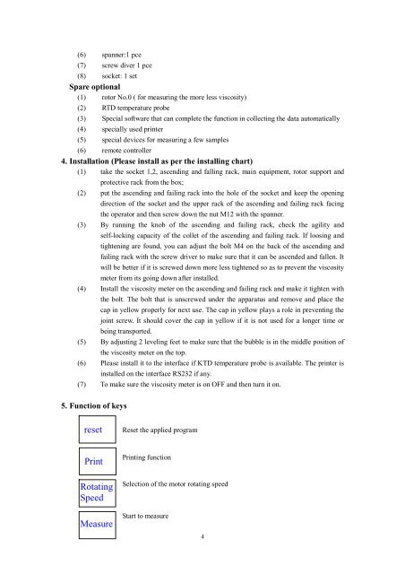
(6) spanner:1 pce(7) screw diver 1 pce(8) socket: 1 setSpare optional(1) rotor No.0 ( <strong>for</strong> measuring the more less viscosity)(2) RTD temperature probe(3) Special software that can <strong>com</strong>plete the function in collecting the data automatically(4) specially used printer(5) special devices <strong>for</strong> measuring a few samples(6) remote controller4. Installation (Please install as per the installing chart)(1) take the socket 1,2, ascending <strong>and</strong> falling rack, main equipment, rotor support <strong>and</strong>protective rack from the box;(2) put the ascending <strong>and</strong> failing rack into the hole of the socket <strong>and</strong> keep the openingdirection of the socket <strong>and</strong> the upper rack of the ascending <strong>and</strong> failing rack facingthe operator <strong>and</strong> then screw down the nut M12 with the spanner.(3) By running the knob of the ascending <strong>and</strong> failing rack, check the agility <strong>and</strong>self-locking capacity of the collet of the ascending <strong>and</strong> failing rack. If loosing <strong>and</strong>tightening are found, you can adjust the bolt M4 on the back of the ascending <strong>and</strong>failing rack with the screw driver to make sure that it can be ascended <strong>and</strong> fallen. Itwill be better if it is screwed down more less tightened so as to prevent the viscositymeter from its going down after installed.(4) Install the viscosity meter on the ascending <strong>and</strong> failing rack <strong>and</strong> make it tighten withthe bolt. The bolt that is unscrewed under the apparatus <strong>and</strong> remove <strong>and</strong> place thecap in yellow properly <strong>for</strong> next use. The cap in yellow plays a role in preventing thejoint screw. It should cover the cap in yellow if it is not used <strong>for</strong> a longer time orbeing transported.(5) By adjusting 2 leveling feet to make sure that the bubble is in the middle position ofthe viscosity meter on the top.(6) Please install it to the interface if KTD temperature probe is available. The printer isinstalled on the interface RS232 if any.(7) To make sure the viscosity meter is on OFF <strong>and</strong> then turn it on.5. Function of keysresetReset the applied programPrintPrinting functionRotatingSpeedSelection of the motor rotating speedMeasureStart to measure4