Operation Manual - Mrclab.com
Operation Manual - Mrclab.com
Operation Manual - Mrclab.com
- No tags were found...

You also want an ePaper? Increase the reach of your titles
YUMPU automatically turns print PDFs into web optimized ePapers that Google loves.
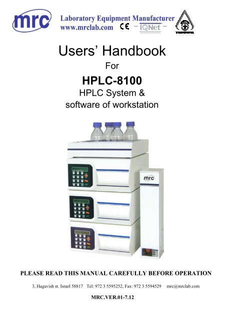
HPLC-8100 HPLC ChromatographCONTENTCHAPTER ONE PREFACESOP’s in this manual...............................................................................................1Unpacking ............................................... ..........................................................................1Packing list............................................. ............................................................................1CHAPTER TWO HPLC PUMPBrief descriptions of HPLC Pump ......................................................................................21. Front view of HPLC Pump ..................................... .....................................................22. Rear panel view of the HPLC pump ..................... .......................................................3<strong>Operation</strong> of HPLC pump........................... .......... ..............................................................41. Connection of power supply ...................................... ..................................................42. User’s page characteristics and operation......................... ...........................................4Simple Maintenance: ............................................................ ..............................................71. Replacing and purging the pump head.......................... ...............................................7HPLC pump technical parameters ...................................... ..............................................10CHAPTER THREE UV DETECTORBrief descriptions of UV Detector ........................................................................ 111. General description .......................................... ......................................................... 112. Optical path of the UV detector ..................... ........................................................... 11Preparation of UV detector before the operation:.................................................121. Front view of UV detector .............................................................................122. Rear view of UV detector ..............................................................................143. Power supply, ON/OFF, and self-test.............................................................14<strong>Operation</strong> of UV detector......................................................................................151. Internal software structure and menu explanation .........................................152. Installation of flow cell ..................................................................................171
HPLC-8100 HPLC ChromatographSimple Maintenance..............................................................................................181. Lamp maintenance .........................................................................................182. Cleaning the flow cell ....................................................................................183. Flow cell.........................................................................................................19Technical data of UV detector ..............................................................................20CHAPTER FOUR CONNECTIONConnection of detector to HPLC system ..............................................................21Connection of UV detector with <strong>com</strong>puter ...........................................................22CHAPTER FIVE WORK STATION controlled instrumentBrief instructions of work station .........................................................................231. Characteristics of work station.......................................................................232. Running environment of work station software.............................................233. Integral environment of work station.............................................................24<strong>Operation</strong> of work station .....................................................................................251. Preparation of work station before the operation...........................................252. <strong>Operation</strong> procedures of work station............................................................272
CHAPTER ONE PREFACEHPLC-8100 HPLC ChromatographThanks for purchasing Model HPLC-8100 Liquid Chromatograph developed by our <strong>com</strong>pany.This device includes HPLC Pump,UV detector and software of work station. Read this manualcarefully before the operation.SOP’s in this manualThe Standard <strong>Operation</strong> Procedures (SOP) provided with this manual offer a convenient way ofstructuring <strong>com</strong>plex tasks in the operation of your HPLC pump and UV detector. They includestep-by-step instructions leading the user through all routine tasks during the operation. They canbe used for documentation purpose and be copied, applied signed, and filed in order to documentthe performance of the instrument.Please operate the instrument and all accessories according to instructions and SOP’s in thismanual. This ensures proper results and longevity of the instrument.UnpackingUnpack the instrument and check the device and accessories thoroughly for any damage that mayhave occurred during transport. If necessary, put forward any claim for damages to the carrierand inform of your local dealer immediately.Use packing list to check the device delivery is <strong>com</strong>plete. Please contact your local dealer if youmiss something or if you need support. Please fill out the guarantee registration card and return itto the local dealer immediately.Remove the transport protections from the display.Packing listPacking list (Standard delivery)QuantityHPLC PumpUV DetectorStandard flow cellStart-up kit,analytical<strong>Operation</strong> manualPower cable 220V/10ARS232 CableSoftware of work station1Set1Set1Pc.1Set1Copy2Pcs.1Pcs.1Set1
CHAPTER TWO HPLC PUMPHPLC-8100 HPLC ChromatographBrief descriptions of HPLC Pump1. Front view of HPLC PumpFig. 1 Front view of Pump1-Display information area 2- Foil key area 3-Pump front doorDisplay area and key area (1 and 2 in Fig.1)Fig 2 Display area and key area1-Display information area2.2-Purge START/STOP2.4-Arrow keys and ENTER key2.1 Pump START/STOP2.3-Numeric key pad2
Connections of piping (3 and 4 in Fig, 1)HPLC-8100 HPLC ChromatographFig.3 Piping connection of Pump head with pressure transducer3.1-Backflushing capillaries3.2-Outlet valve housing3.3-Head set screws3.4-Inlet valve housing3.5-Eluent outlet4.1-Inlets to transducer4.2-Peek screws by hands4.3-De-areation screw4.4-Eluent outlet2. Rear panel view of the HPLC pumpFig. 4 Rear panel view of the HPLC pump4.1 Power connector 4.2 Fuse <strong>com</strong>partment4.3 ON/OFF Switch 4.4 12V Ventilator4.5 12V Ventilator 4.7 Gradient program trigger4.8 Plug for solvent organizer 4.9 RS-232 Interface3
HPLC-8100 HPLC Chromatograph<strong>Operation</strong> of HPLC pumpHPLC pump is controlled by keyboard and work station of the <strong>com</strong>puter control. The followingdescribes the operation of the keyboard. The work station of the <strong>com</strong>puter control is described inthe Chapter four.1. Connection of power supplyHPLC Pump is equipped with a universal power supply for input voltage 220±20V Ac,frequency 50 ±0.5Hz. 1KVA stabilizer is required. Connect the power cable to the socket onthe rear panel of the instrument and switch on the device with the ON/OFF key, see (4.1) and(4.3) in Fig.4.CAUTION: Make sure that the main power supply is properly grounded and acorrect three-pronged power cable is used. Connecting the instrument to faulty powersockets can cause damages.2. User’s page characteristics and operationPress the key in 2.2 of Fig.2 at any time to make system purge, again press this key to stoppurging.CAUTION: If the purge is required, first loose “PEEK screw by hands”, see 4.2 inFig3, otherwise chromatographic column will be damaged!Self-test pageAfter switching on the instrument, firstly enter into the self-test status, display the self-test pageas shown the follows:BFRL HPLC-8100 HPLC PUMPRAM TEST OKBFRL HPLC-8100 HPLC PUMPEEPROM TEST OKPage of switching onFLOW►0.00ml P.max 19.0 MPaPRES 0.0mPa P.min 0.0 MPaASTOPTurn on the switch of the pump on this page. After <strong>com</strong>pleting the self-test of the pump, theabove page is appeared. Press 2.1 key in Fig.2 to make the pump START/STOP.CAUTION: Never run the HPLC Pump without liquid in the pump head or in the pistonbackflushing <strong>com</strong>partment. Operating the pump without solvent may lead to damage of thepump sealsSOP 1:4
HPLC-8100 HPLC ChromatographPress “ENTER” key, move the triangle cursor among “Flow”, “P. max.” and “P. min.”As shown in Fig., the triangle cursor points “Flow”, use the numeric key for flow input, againpress “ENTER” key to confirm the setting. Therefore, the system flow is transferred to the flowvalue of setting.As the same operation, press “ENTER” key to move the cursor to “P. max.” and “P. min”.The data value enables to be renewed with the same operation.Press the arrow “▲”and“▼”keys to enter into the other pages.Vocabulary explanation:Flow - Current flow of pumpP. max. - Maximum pressure allowable for the systemA Pump - Series number of PumpPressure -Current pressure of pumpP. min. -Minimum pressure of systemStop -Running status of pump(When pump stops, display“Stop”, whenrunning, display“Run”)Gradient mode pageGE MODE: High-Pressure Gradient1: HP. GE A 2: HP. GE B 3: LP. GEThis page is the selection page of the gradient mode of the current pumpPress the numerical keys 1, 2 or 3, again press ENTER key to select the corresponding gradientmode.SOP 2Press 1, 2 or 3 keys, again press “ENTER” key to select the corresponding gradient mode.Press“▲” and“▼”keys to enter into the other pages.Vocabulary explanation:HP. GE A - Pump located in A pump system of binary high pressure systemHP. GE B - B pump in binary high pressure systemLP. GE - Pump in quarter low pressure gradient system.During the operation of high pressure gradient and low pressure gradient, the correspondingsetting is required in “SY8000 chromatograph work station to realize the work station to fullycontrol the instrument.(See the control section in the operation manual of data work station ofchromatograph.Pressure zeroing pageAPressure zero AdjENTER to zero adjThis page is the pressure zeroing page. There is no need for the user to operate it. User can press“ENTER” key to adjust the pressure zeroing unless “PEEK screw is loosen and the pressurevalue does not display the zero in the page of switching on the instrument.SOP 35
HPLC-8100 HPLC ChromatographSimple Maintenance:1. Replacing and purging the pump head1.1 Disassembling the pump headCAUTION: If the organic residential is remained in the pump head, it may cause theskin irritation..Use proper cleaning reagent to purge the pump head, and then to purge it with the distilled water.After so, `the replacement for the pump head is made.SOP 6:1. Loosen“Eluent outlet”, see Fig.3(3.5),Loosen inlet valve housing, see Fig. 3(3.4).2. Use 3#(3mm)hexagonal spanner to loose “fixing screws of pump head “on the twoslanting angles, see Fig. 3 (3.3). Remove them.3. Carefully loosen the rest two screws about half a turn, alternating from one to the otherto avoid the damaging the pump head. Unscrew the two screws strictly alternating dueto strong force of springs, it may be help to either clamp the pump head or to press oneof its side surfaces against a table with one hand and remove it.4. Carefully remove the pump headDisassembling and Check pistonSOP 71. Detach the pump head.2. The piston is shown as Fig.5(11). A clipper (nipper) is available for detaching it.Use the clipper to clamp the metal material part of the piston end and carefully pull it out alongon the straight line.CAUTION:If the piston is broken, the pump head must be thoroughly checked for the damage.1.2 Detaching the pump head1) Detach the pump head.2) Detach the piston.3) Loosen the two “retaining plate screws” as shown in Fig.5(20),half a turn,alternating from one to the other to avoid damaging the “retaining plate”.4) Because the two screws are very tight, it may be help to either clamp the pump head orto press one of its side surfaces against a table with one hand while loosening thescrews.5) Unscrew the screws strictly alternating due to strong force of the spring behind the plateas shown in Fig. 5(10)and remove them.6) Dismount the retaining plate, see Fig.5(12).7) The moment, remove “spring guide sleeve,see Fig.5(19)and “spring:”.8) Use the spinner to loosen “ retaining nut” as shown in Fig.5(9), half a turn alternately.9) Remove “Rear pump head” as shown in Fig 5(17),and take out(15) and(16).10)Insert the piston into “high pressure seal ring”, and then pull it out. The moment, theseal ring is adhered on the piston and take it out.7
HPLC-8100 HPLC ChromatographFig. 5Disassemble diagram of the pump head and parts sequence.Ser. No1234567891011121314151617181920Part’s NameRetaining screw of pump headFront pump headFront connection tubeHigh pressure seal ringStainless steel block ringO-ringRear purge tubeLow pressure seal ringRetaining boltSpringPistonRetaining plateValve sleeveSingle way valvePlastic baffle ringRear purge tubeRear pump headBushingGuide for springScrew of retaining plateTable 1Pump head8
1.3 Assembling the pump headHPLC-8100 HPLC ChromatographAll positions of <strong>com</strong>ponents of the pump head refer to Fig 5SOP 81. Detach the pump head to check it. After solving the problems, mount it into (4), 15),and(5)at the front pump head in regular sequence.2. After mounting the pump head, piston the head in a straight line onto the pumphousing (9),and then take the “piston” out .3. Mount “spring guide sleeve and spring”, see Fig.5(19)and (10).4. Install “retaining plate”, see Fig.5(12).5. Insert and tighten the two screws strictly alternating due to strong force of the springbehind the plate.6. Alternating from one to the next, tighten two screws half a turn at a time on theretaining board so as not to damage it.7. Carefully insert the piston rod, see Fig.5(11)without bending or quenching the rod..8. Both “the spacing bolts” and “retaining board screws “must be tightened securelyas before.1.4 Installing the pump headSOP 9:1. Make sure that the pump head has been correctly assembled.2. Piston the head in a straight line onto the pump housing..3. Tighten all four pump head set screws a few turns by hand, see Fig.5(10).4. Alternating from one to the next, tighten two diagonally opposed screws half a turn at aTime until the pump head is correctly seated5. Tighten the two remaining screws. Make sure that all four pump head set screws areSecurely tightened, see Fig. 5 (1).6. Mount the capillary connection between the pump head outlet and the pressuretransducer.9
HPLC pump technical parametersFlow rate range: 0.01~9.99 ml/minStructure of Pump: Dual piston rod, series type oscillatingdisplacement pumpFlow accuracy
CHAPTER THREE UV DetectorHPLC-8100 HPLC ChromatographBrief descriptions of UV Detector1. General descriptionBFRL UV detector is a valuable new type detector,especially developed for the routine analysis.The deuterium lamp is used as the light source of the instrument.UV detector selects the flow cell of standard type(Optical path:10mm,volume:10µL,the flowrate range of eluent phase of UV detector is available from 0.001~9.999mL/min.After powering up, the UV detector performs the self test and calibration automatically.● The internal software includes an auto-calibration of the wavelength scale. Theposition of the grating reflection (0. order) will be located automatically.● The deuterium lamp with the wavelength of 656nm is used to check and to calibratethe display.The distance of the wavelength passed through the monochromator should be 1nm for perstep, arbitrary setting can be made in the range of 190nm to 740nm. Accuracy is ±2nm.In addition, UV detector still have the function of the whole wavelength or the wavelengthrange set by user to process stopping the flow scanning.UV detector provides with very low noise(2×10 -5 AU)and shift(15×10 -5 AU/h),availablefor auto-zeroing of the full scale.Key pad is clear, clean film, convenient for <strong>com</strong>pleting the operation.The control and data acquisition of the UV detector is digitalization to secure runningwithout the trouble.2. Optical path of the UV detector1. Deuterium lamp2. Slit3. Filter4. Concave mirror5. Plane grating monochromator6. Half transparent mirror7. Flow cell8. Photodiode (Sample)9. Photodiode (Reference)Fig. 6Optical Path of UV detectorInstructions for optical pathA beam of emitted light from the deuterium lamp(1)is faded out by a slit(2). After passing afilter(3) it is focused by a concave mirror(4)on a plane grating monochromator(5),soas to obtain a beam light of characteristic wavelength. The bream is then split by a halftransparent mirror(6). One part beam delivers the reference signal(9),and the other afterpathing the flow cell(7)irradiates to photodiode (8) to produce the measurement signal.11
HPLC-8100 HPLC ChromatographPreparation of UV detector before the operation:1. Front view of UV detector1.Display information area 2.Foil key pad 3.UV detcector front doorFig.7Display area and foil key padFront panel of UV detector and flow cellInformation display areaFig. 8 Display area and foil key pad1. Display area 2. Control function key3.Input key4. Arrow key and ENTER keyABS-0.0001 AUWAVELAMP IS LIT254 nmFig. 9Display information areaInformation display area displays real time parameters and result data of UV detector.Foil key pad areaFoil key pad includes control function key(Auto-zeroing key and running program key),Data12
input key, arrows keys and ENTER key.HPLC-8100 HPLC ChromatographAutoZeroProgAuto-zeroingPress this key to adjust the baseline of the instrument(baseline returns to zero).Normally press this key before the analysis. Use sampling valve of signal cable(7725i) equipped with the instrument for sampling, the work station willautomatically control to process the zeroing adjustment for once at the same timethe valve is changed over. The moment, there is no need for user to press this keyagain.Running programPress this key to run the wavelength scanning program set by user.Data input keyAs shown in Fig.8-3. Data input key is used to modify the operation parameters.At the same time, CE key is set at the key area(CANCEL key). It is used tocancel error parameters being input.Arrow keys and ENTER keyAs shown in Fig.8-4. Arrow keys are used to turn over the pages. “Enter” key isused to confirm currently entered or selected parameters.Flow cell areaFig. 10Flow cell area and flow cell1. Knurled cell screw 2. Flow cell cradle3. Inlet liquid 4. Cell body5. Outlet liquidInlet liquid of the flow cell is connected to column, outlet liquid is connected to waste liquidbottle or collecting device. Every constituent separated by the column is entered into the flowcell to make the determination.13
HPLC-8100 HPLC Chromatograph2. Rear view of UV detectorFig. 11 Rear view of UV detector1.RS—232 interface3. Power supply, ON/OFF, and self-test2.Remote terminal3. Analog output 4. 24V ventilator5.12V ventilator 6. Power switch7., power socket 8. Slow melting fuse(1A)UV detector operates with 220±20V AC of 50±0.5Hz. 1A slow melting fuse is used. Thesetting is done by the manufacture on custom request. The actual setting is indicated onrear panel of the instrument (Fig. 12).theCaution:Cut off power supply before opening cover.220±20V 50±0.5 Hz100VAFUSE: 1A SLOWFig. 12 Indication of the input voltageCAUTION: Make certain that the correct voltage has been set on the rear panel of theinstrument, the power supply is reliably grounded and a corresponding 3-pole power cableis used.Connect the detector to the power supply. Switch on the instrument. Power switch is on the rearpart of the instrument.After switching on, the instrument first performs the self-test as follows:BFRL UV/VIS DETECTORRAM TEST OK14
HPLC-8100 HPLC ChromatographBFRL UV/VIS DETECTOREEPROM TEST OK >Afterwards, display model of instrument and simultaneously the deuterium lamp is lit.BFRL UV/VISPre-heatingDETECTOR>Power on the instrument a time, the wavelength should be calibrated for once, display asfollows:BFRL UV/VISCheck Home PosDETECTOR>After a certain period of zeroing calibration(about one minute), display as follows:BFRL UV/VISWave calibDETECTOR>The detector enters into the following page afterward. This page is also a acquiesce page ofUV detector:ABS -0.0001 AU LAMP IS LITWAVE254 nm15 minutes later, UV detector is ready for the analytical determination.<strong>Operation</strong> of UV detector1. Internal software structure and menu explanationThe software is divided into several menus. Settings and operation modes are made on everymenu. Use“▲”and “▼”keys to enter into each menu as shown in Fig.13.ABS -0.0001 AU LAMP IS LITWAVE254 nmRESPONSE 1.00 (0.05-10)SPress [ENTER] TO Change15
HPLC-8100 HPLC ChromatographD2 LAMP ENERGY SMPL 0.794583USED TIME 50.3 h REF. 0.401205SERIAL 825365 Option1:D2 OFF 2:WAVE CALIB [Enter]BFRL UV/VIS DETECTORSN. 825282 Rev: 1.70Fig. 13Menu sequence of UV detectorDescribe every menu in details as follows. When the parameter on the menu is required tomodify, use the data input key to modify the setting of the corresponding parameter. Thus pressthe “ENTER” key,the moment the value just input is confirmed. If error parameter is input, use“CE”key to delete it, then input the correct one according to the procedures mentioned above.Signal menuABS -0.0001AU LAMP IS LITWAVE254nmSignal menu(or main menu)includes: absorbance(signal intensity),D 2 lamp status andwavelength. Absorbance is in unit of “AU”. D 2 lamp status shows “ON” and “OFF”. Thewavelength is in unit of“nm”.The signal value for real measurement displays in four digits. The wavelength range is from 190to 740nm for arbitrary setting.Response time menuRESPONCEPress [Enter] TO Change1.00 (0.05-10)SUse the response time (time constant) to make the signal smooth. Press ENTER key to select theinput. Respectively set: 0.05,0.10,0.15,0.20,0.25,0.30,0.35,0.40,0.45,0.50,0.55,0.60,0.65,0.70,0.75,0.80,0.85,0.90,0.95,1.00,1.50,2.00,2.50,3.00,3.50,4.00,4.50,5.00,6.00,7.00,8.00,9.00,10.00sec. The value is more bigger, the signal is more smooth.Time constant of 1second. is satisfied with the most of the analysis requirements.D 2 lamp energy and using time menuD 2 LAMP ENERGY SMPL 0.794583USED TIME 50.3 h REF 0.401205D 2 lamp energy menu displayed is the energy values of ultraviolet light received from the16
HPLC-8100 HPLC Chromatographphotodiode on the reference signal board and the sample of the detector. These two energyvalues can be directly known the energy of the deuterium lamp. If these energy values show toosmall, replace D 2 lamp on time.The used time means the ignition time of D 2 lamp.Series No. and operation function menuSERIAL 825365 Option1:D2 OFF 2:WAVE CALB [Enter]Series No. means production series No. of the detector, not delivery series No.<strong>Operation</strong> function menu includes:“1:OFF lamp”,“2:Wavelength calibration”. Respectivelyinput the numeric number corresponded to the operation function under this menu. Press“Enter”key to <strong>com</strong>plete the corresponding function. For example: Complete the operation ofswitching off the lamp, press the corresponding digit“1”under this menu and then press“Enter”key to finish the operation of OFF lamp. As the same, <strong>com</strong>plete the operation of the wavelengthcalibration, press the corresponding digit“2”on this menu,after so, press“Enter”key to finishthe operation of the wavelength calibration.Identification menuBFRL UV/VIS DETECTORSN. 825282 Rev: 170Identification menu displays model and name of the instrument, simultaneously displayproduction series number of the instrument and software version No. It is not necessary for theuser to modify any item in the identification menu.2. Installation of flow cellThe flow cell of UV detector has not been delivered during transport. There is a dummy flow cellwithout any of optics equipped with the instrument. Before the detector is used, a properstandard flow cell must be installed.CAUTION: There is no need to change the status of the instrument and the lampduring the replacement of the flow cell.SOP 1 Installation of flow cellThis instruction refers to UV detector as shown in Fig10 flow cell area and flow cell (see thepreparation of UV detector before the operation in the concerned section).a) Loosen the two knurled cell screws (1) by hand and remove them.b) Pull out the flow cell cradle (2).c) Take the cell or dummy cell with two figures and remove it upward.d) Insert the new flow cell and make sure engraved specification towards the user(….can be read) and the fixing hole on the back side of the cell meets thecorresponding metal pin.e) Now push the <strong>com</strong>plete system towards the housing, insert the two screws andtighten them manually.17
HPLC-8100 HPLC ChromatographSimple Maintenance1. Lamp maintenanceThe deuterium used with UV detector has an extended lifetime to ensure long-time functionalityand reliable measurements with low noise and baseline drift as well as high sensitivity. (life timeabout 2000 hours). The actual using time of the deuterium lamp depends on different factors, likethe number of lamp starts, the average burning time and your requirements concerning noise andsensitivity.To check the functionality of the lamp, the two intensity values of sample and reference (see“D 2lamp energy and used time” menu),the help information for D 2lamp can be found there. Thereference value refers to the intensity of the light measured in the reference channel and be usedfor checking the quality of the lamp.We re<strong>com</strong>mend to check the reference value at regular intervals under the conditions mentionedabove(dummy cell, λ= 240nm). This applies especially in case higher noise levels or decreasedsensitivity is observed on working with UV detector. In these observations coincide with areference value of approx. 0.1 or less, or used time is over 2000h, a new deuterium lamp shouldbe installed.2. Cleaning the flow cellNoisy baselines and low sensitivities may be due to a dirty flow cell. This may also be indicatedby a low absorbance value in the signal menu when flushing the cell with pure solvent. Thatshows the flow cell has been polluted. In most cases it is sufficient to purge the flow cellaccording to the following SOP.SOP 1 Purging the flow cellThis instruction applies to the flow cell delivered with UV detectora) Purge the flow cell using one of following solvents: sodium dodecyle sulfate(SDS), 1m HCL, 1m NaOH, ethanol, or acetone.b) Run the solvent through the flow cell using a syring and leave for approximately 5minutes.c) Rinse extensively with water and the blow dry using a gentle stream of purenitrogen.CAUTION: Never dry with <strong>com</strong>pressed air to blow the flow cell, this will containmicrodroplets of oil that will coat the cell.CAUTION: When the optics module is not in use, disconnect the flow cell and cleanouter traces of salt and protein with a syringe filled with distilled water.Before storing the flow cell inject a dilute solution (10-25%) of ethanol ori-propanol to prevent microbial growth.CAUTION: In case the flow cell purging do not provide sufficient success, all flow cellscan easily be disassembled for cleaning the lenses.18
HPLC-8100 HPLC Chromatograph3. Flow cellFig.17 Sectional view of flow cellSOP 2Cleaning the flow cellThis instruction applies to the flow cells enclosed in UV detector.a) Unscrew the outer threads with 3mm hexagonal spanner enclosed in the flowcell’s delivery.b) Remove the black gasket that carries the lenses with a pair of tweezers or bygently tapping it on a clean surface. The lens is embedded in the gasket and sealedagainst the flow path with PTFE seal. This seal should be changed every timewhen assembling the flow cell.c) Take out the lenses and clean them by wiping them with a soft cloth or with anappropriate solvent in an ultrasonic bath. Be careful not to touch the lenseswith the figures.d) Reassemble the cell in the reverse manner, making sure that PTFE seal does notblock the light path.e) Tighten the outer threads carefully with the spanner in order not to damage thelenses.19
Technical data of UV detectorWavelengthLamp190~740nmDeuterium lampWavelength accuracy ±2nmScan function Spectral scanningMeasurement range 0~2AUSensitivity 4×10 -5 AU at 240nm and time constant 1.0SNoise 2×10 -5 AUat 240nm and time constant 1.0SBaseline drift 15×10 -5 AUat 240nm and time constant 1.0STime constantIntegrator outputAuto-zero rangeDisplayControlPower supplyWeightDimensions0.05~10.00±1.0VFull scaleHPLC-8100 HPLC Chromatograph2×16DigitsRS232interface, analog output, remote connector220±20 V,50±0.5Hz,100VA8Kg350×190×210mm (L×W×H)20
Better 64MHPLC-8100 HPLC ChromatographOne free series interface on the system board (COM1 and COM2)VGA Color display (better use an accelerated card of graphics)Optical driveMouthPrinterSoftware: Better Windows 20000 operation system3. Integral environment of work stationDouble-click the graphic of chromatograph work station on the table to enter into the intergralenvironmental page of work station.Main menuPrompt buttonRunning indicating lampSpectrogram display windowInformation lineFig 1The main page of the integral environment consists of five parts: main menu, graphic displaywindow, prompt button, controlling menu, running indicating lamp and information line.Main menuAs same as the other application program, according to the different requirement of treating data,all of the function <strong>com</strong>mands are classified, after so, respectively put them into eight menus, soevery menu has own group <strong>com</strong>mands.Prompt buttonSome <strong>com</strong>mon used functions in the main menu are marked on these buttons with displaypresentation. Therefore, these functions in <strong>com</strong>mon use can be directly selected by pressing theconcerned button without selecting it from the menu in order to speed up the operation.Spectrogram display window: including plotting area, time coordinate scale, level coordinatescale and peak hold time.Plotting area——Actively display the real time spectrogram area, the sizes can be automaticallyadjusted with the size change of the spectrogram display window. When the user makes thespectrogram display window shortening to a certain extent, the system automatically delete the24
HPLC-8100 HPLC Chromatographplotting coordinate scale and display of the hold time to secure observing the graphics clearlyeven in a small size window.Time coordinate scale——It is used as X axle coordinate scale, in unit: Min. The initial value isautomatically adjusted with the change of the sampling time. Modify the full time difference on“screen plotting parameter edition”, minimum time is 1min.Level coordinate scale——It is used as Y axle coordinate scale of the spectrogram plotting, inunit : Mv. Modify the full scale maximum value and minimum value on “screen plottingparameter”.Peak hold time — — During starting sampling, automatically display the hold time afterappearing the chromatograph peak top. In the “screen plotting parameter edition”, select “nodisplay the hold time” to close it.Running indicating lampThe red lamp is flash when the data is acquiring, while the green lamp is lit under the state ofpreparationInformation lineIt displays currently inputting level, sampling time, current sample name and current time.As the main page mentioned above, when you select some <strong>com</strong>mand in the main menu orsingle-click some of prompt button, the corresponding window or dialogue block will beappeared.<strong>Operation</strong> of work station1. Preparation of work station before the operationBefore operating the work station, HPLC-8100 series HPLC Chromatograph should be connectedwith the <strong>com</strong>puter installed the work station software. Power the instrument on. When<strong>com</strong>pleting the self test of the instrument, the <strong>com</strong>puter displays the following page, That showsthe connection of the <strong>com</strong>puter is successful.Success for the connectionCurrent WavelengthCurrent setting flow Fig 2Current pressure of25
HPLC-8100 HPLC ChromatographAfter success for the connection of the instrument with the <strong>com</strong>puter, the operation page of thework station simultaneously display current setting flow speed and current pressure of pump andcurrent wavelength of UV detector.If the instrument failed to connect to the instrument, under “instrument control” menu, makesetting of <strong>com</strong>municating terminal and let the terminal number of the setting be in accord withthe terminal number connected with the instrument shown as the following figure:Setting of <strong>com</strong>municating terminalFig. 3After success for the connection of the instrument with work station, firstly click “Pump” or“Detector” on the work station, check the setting of working parameters of the pump anddetector as shown in the following:Setting of pumpFig. 426
HPLC-8100 HPLC ChromatographSetting of detectorFig. 5The pump requires to set the control mode (control mode divides: single pump, double pumprunning independently, double pump high pressure gradient and single pump low pressuregradient), If using gradient table, pump flow and up limit and down limit of pressure; Detectorrequires to set the wavelength and deuterium lamp status, if using the wavelength program table,etc. The sensitivity of the detector is set by the acqueuiescence. The spectral scanning is setaccording to the concerning conditions when it is required.2. <strong>Operation</strong> procedures of work stationUse the work station software to do the experiment after the settings mentioned above. Asexample for outer standard method as follows:<strong>Operation</strong> procedures of outer standard method1. Create a new method file parameter to do the experiment. Its procedures are as follows:1) Start HPLC chromatograph and work station software;Fig. 627
HPLC-8100 HPLC Chromatograph2) Record parameters of editing dataSignal-click the graphic of “data record parameter” to appear the window of the method editing,set the position of file storage.Fig.73) Editing integral parameterSingle-click the graphic of “integral parameter” to appear the window of the method edition.Where set the integral parameter value and edit “ time program table”, If it is not set any, onlypress the acquiescent value.4) Edit “sample information” tableFig. 8Click the graphic of “ sample information”, edit “sample information table, define the name ofthe experimentalized data file as “sample name” as shown in the following:28
HPLC-8100 HPLC ChromatographFig.95) Standard sample anslysisWhen running the chromatograph stable, input the standard sample. During valve sampling, atthe same time, the program automatically process the data acquisition to the spectragram, andremark the hold time. When all of peaks are appeared, stop the program manually, or set “ stoptime” in “integral parameter ” table to stop it automatically.6) Sample analysisInput the unknown sample. As same as the procedures 5. (this step can be made at last.) Data fileobtained from the procedures 5 and 6 will be saved automatically by the system.. The data filesare automatically, continuously named. Such as: Test001.dat, Test002.dat, Test003.dat……..7) Draft the calibration curvea. Edit the quantitative parameterClick the graphic of “ the quantitative parameter” to appear the window of the methodedition:Fig. 10Set well “quantitative mode”, “quantitative method (outer standard method), “ standard( eight concentration standard sample, select “ eight points”), “standard concentrationunit” and “sample result unit”.b. Filling in constituent tableClick the graphic of “constituent table” to appear the window of the method edition, fill inthe analytical sample constituent table name, hold time and series standard concentration.29
HPLC-8100 HPLC Chromatographc. Definition calibration curveFig.11a) Click the graphic of “calibration curve” to appear the window of the method edition.Fig.12b) Definite spectrogram peak file required at every point. Firstly use the mouth to moveto the point number of the standard sample, then click the right key, this number iscovered by blue frame, again click the left key to select the menu:Fig.13c) Select “ Add” item (this operation shows at the same concentration point, add the data30
HPLC-8100 HPLC Chromatographof several parallel experiment to calculate the mean value), the window of“spectrogram selection” is appeared.Fig.14Here select the corresponding spectrogram file. “+” appears before the file of sequencenumber point. After <strong>com</strong>pleting the definition foe every points, click “re-read peak file” todisplay the calibration curve.8) Check sample resultEnter “re-treatment” page, click the graphic of “open data file” to appear the window of“spectrogram selection”, select the sample spectrogram file here as follows:Fig.15And then click the button of “re-calculate”, Again click the graphic of “screen report” to look atthe screen report table.31
HPLC-8100 HPLC Chromatograph9) Printing reportFig.162. Recall the method file parameters originally saved to do the experiment.1) Use the mode of “open method”Select “open method” in “file” menu of work station, appear the window of “method fileselection”, select the method file here as shown as follows:Fig.17Sampling is directly made after recalling the method file without the operation procedures from1-7. After the experiment, the step 8 is made directly to look at the sample content.2) Use “mode of “open method from data”Select “open method from data” in “file” menu of work station (it is another mode for recallingthe method file, only recall the method file with the date), appear the window of “spectrogramselection”, the moment, select the method file here as shown as the follows:32
HPLC-8100 HPLC ChromatographFig.18The descriptions as same as the method above mentioned, Sampling analysis can be made afterrecalling the method file without the operation procedures from 1-7 steps. The procedure of step8 is made after <strong>com</strong>pleting the experiment in order to directly obverse the sample content.33