Installation Operation Maintenance
Installation Operation Maintenance
Installation Operation Maintenance

You also want an ePaper? Increase the reach of your titles
YUMPU automatically turns print PDFs into web optimized ePapers that Google loves.
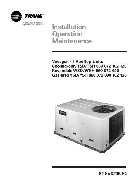
<strong>Installation</strong><strong>Operation</strong><strong>Maintenance</strong>Voyager I Rooftop UnitsCooling-only TSD/TSH 060 072 102 120Reversible WSD/WSH 060 072 090Gas-fired YSD/YSH 060 072 090 102 120RT-SVX20B-E4
ContentsUnit Options 44Hot water coil 44Electric Heater 45Soft Starter 450 - 25% fresh air hood 46Barometric relief 47<strong>Operation</strong> 48<strong>Operation</strong> with a conventional thermostat 48Setting the economizer 50Test procedures 52Test modes 53Unit Start-up 54Cooling without an Economizer 56Low Ambient <strong>Operation</strong> 57Cooling with an Economizer 57Economizer Set-Up 58ReliaTel Control Heating <strong>Operation</strong> 58Ignition Module 58Final installation checklist 59<strong>Maintenance</strong> 60End user routine maintenance 60Service technician maintenance 61Troubleshooting 62RT-SVX20B-E45
<strong>Installation</strong>Dimensions/Weights/ClearancesFigure 3 - Minimum clearancesThe structure accommodating theunit(s) must be designed to supportthe equipment in operation, as aminimum. Refer to Table 2 and thespace requirement plan.Table 1 - Minimum recommended clearancesUnit sizeMimum clearances (mm)1 2 3 4 5TSD/TSH 060 1829 1219 914 914 914TSD/TSH 072 1829 1219 914 914 914TSD/TSH 090 1829 1219 914 914 914TSD/TSH 102 1829 1219 914 914 914TSD/TSH 120 1829 1219 914 914 914YSD/YSH 060 1829 1219 914 914 914YSD/YSH 072 1829 1219 914 914 914YSD/YSH 090 1829 1219 914 914 914YSD/YSH 102 1829 1219 914 914 914YSD/YSH 120 1829 1219 914 914 914WSD/WSH 060 1829 1219 914 914 914WSD/WSH 072 1829 1219 914 914 914WSD/WSH 090 1829 1219 914 914 914Table 2 - Unit weights and center of gravityUnit SizeMaximum weight Corner weight (1) Center of gravityShipping(kg)Net(kg)A(kg)B(kg)C(kg)D(kg)Length(mm)Notes:(1) Corner weights are given for information only. All models must be supported continuously by a curb orequivalent frame support.Width(mm)TSD/TSH 060 259 235 75 56 48 56 790 480TSD/TSH 072 365 326 107 83 58 78 970 560TSD/TSH 090 428 389 131 101 67 89 970 530TSD/TSH 102 445 405 133 106 72 94 990 560TSD/TSH 120 485 445 147 115 81 104 990 560YSD/YSH 060 285 260 81 64 54 62 810 510YSD/YSH 072 390 350 113 90 64 83 990 560YSD/YSH 090 458 419 139 110 75 95 970 530YSD/YSH 102 474 434 141 114 79 100 1020 560YSD/YSH 120 520 481 155 126 89 111 1020 560WSD/WSH 060 266 241 77 58 49 58 790 480WSD/WSH 072 408 368 122 93 66 87 970 560WSD/WSH 090 418 378 128 95 67 88 970 530RT-SVX20B-E47
<strong>Installation</strong>Figure 4ACenter ofgravity lengthBCenter ofgravity widthDCenter ofgravityCTable 3 - Factory-installed options and accessories net weights (kg)Unit sizeEconomizerBarometricReliefMotorizedOutside AirDamperManualOutside AirDamperNotes:(1) Weights for options not listed are < 3 kg.(2) Net weight should be added to unit weight when ordering factory-installed accessories.(3) Some accessories are not available on all units.Roof CurbOversizedMotorElectricHeatersHot watercoilTSD/TSH 060 11,8 3,2 9,1 7,3 31,8 - 6,8 14,0TSD/TSH 072 16,3 4,5 13,6 11,8 52,2 3,6 13,6 17,0TSD/TSH 090 16,3 4,5 13,6 11,8 52,2 3,6 13,6 17,0TSD/TSH 1020 16,3 4,5 13,6 11,8 52,2 3,6 13,6 19,0TSD/TSH 120 16,3 4,5 13,6 11,8 52,2 3,6 13,6 19,0YSD/YSH 060 11,8 3,2 9,1 7,3 31,8 - 6,8YSD/YSH 072 16,3 4,5 13,6 11,8 52,2 3,6 13,6YSD/YSH 090 16,3 4,5 13,6 11,8 52,2 3,6 13,6YSD/YSH 102 16,3 4,5 13,6 11,8 52,2 3,6 13,6YSD/YSH 120 16,3 4,5 13,6 11,8 52,2 3,6 13,6WSD/WSH 060 11,8 3,2 9,1 7,3 31,8 - 6,8 14,0WSD/WSH 072 16,3 4,5 13,6 11,8 52,2 3,6 13,6 17,0WSD/WSH 090 16,3 4,5 13,6 11,8 52,2 3,6 13,6 17,08RT-SVX20B-E4
<strong>Installation</strong>Installing the unitDischarge ConversionIf a unit is to be converted toVertical discharge, a panel must beacquired from Trane.If a unit is to be converted toHorizontal discharge, the followingconversion must be performed:1. Remove the return and supplyduct covers.2. Apply gasket to the return ductcover.Figure 6 - Unit mounting on roof13. Position duct covers as shown inFigure 4. The supply duct cover isinstalled (insulation side down)over the downflow returnopening by engaging one side ofthe panel under a retaining angleand securing the other side with3 screws.4. Slide return duct cover(insulation side up) into supplyopenings until outer edge of theduct cover engages with the tworetaining clips on the ductflanges. Secure the outer edge ofthe each duct cover with twoscrews.Figure 5 - Conversion to horizontaldischarge1 = Supply duct cover, insulation sidedown2 = Return duct cover with gasketinstalled, insulation side up3 = Edge of duct cover goes underretaining angleUnit mounting on roofFix the rooftop curb on the jointbeam of the building's structure.Make the rooftop curb's sealingsurface level using angle bracketsadjusted by screw bolts, locatedaround its perimeter. Place theadhesive seals on the curb's sealingsurface (perimeter and crosspieces). Make the rooftop leak-tightaround the curbs before installingthe unit, in compliance with currentconstruction standards.Note: The unit must be installedperfectly level to ensurecondensates flow from thecondensate tray.The rooftop unit nests into the curband is supported by it. Position theunit, taking care to comply with theindicated directions: the unit'sdischarge and intake openings mustmatch those of the curb.1 = FrameRT-SVX20B-E49
<strong>Installation</strong>Installing the unit on the groundTo install the unit on the ground, itsbase must be level and supportedsecurely. For horizontal dischargeunits, a support is required such asa metal or concrete slab whoseheight must be determinedaccording to the amount of snowcover, to prevent problems withcondensation drainage andobstruction of the external coil. Ifnecessary use an anti-vibrationmaterial between the rooftop unit'sbase and the support.Note: Unit installation must complyto local codesConnection of ductnetwork1) Downflow discharge units(TSD,WSD,YSD)Using the rooftop curb• The rooftop curb must beinsulated on the outside walls atthe discharge and intakeopenings to preventcondensation in the ducts.• The rims around the dischargeand intake openings make itpossible to attach the flanges onthe ends of the ducts. If you areusing rigid duct endsrecommended on the rooftopcurb plan, it is essential to fixthese components beforeinstalling the unit.• For the design of the ductnetwork, comply withrecommendations currentlyapplicable on the market, inparticular:. <strong>Installation</strong> of a section offlexible ducts to limittransmission of the unit'svibrations. Use of movable vanes ordeflectors to reduce the soundlevel.2) Horizontal discharge units(TSH,WSH,YSH)• The intake and discharge ductsmust be insulated (thermalinsulation).• The duct section located outsidemust be leak-tight.• Provide a flexible connector toprevent transmission of the unitvibrations. This flexible ductmust be installed inside thebuilding.Note: In case of use of units witheconomizer option, temperatureand humidity sensors must beinstalled in return duct.Economizer linkage is factorymounted but the damper positionmust be adjusted on site.Figure 7 - Unit installation on the ground1 = Concrete slab10RT-SVX20B-E4
<strong>Installation</strong>Table 4 - Duct dimensions for downflow units (mm)Unit size A B C D E FlangesTSD/YSD/WSD 060 619 357 411 459 356 31TSD/YSD 072/090/102/120WSD 072/090857 451 451 857 356 31Table 5 - Duct dimensions for horizontal units (mm)Unit size A B C DTSH/YSH/WSH 060 591 337 375 438TSH/YSH 072/090/102/120WSH 072/090832 425 606 489Figure 8 - Duct dimensions for downflow unitsBACFigure 9 - Duct dimensions for horizontal unitsDERSSDCRBAS = SupplyR = ReturnS = SupplyR = ReturnRT-SVX20B-E411
<strong>Installation</strong>Condensate drain pipingA 3/4" condensate drain connectionwith P-trap is provided. Follow localcodes and standard piping practiceswhen running the drain line. Installa trap and be sure to fill with waterbefore starting the unit. Pitch theline downward, away from the unitto avoid long, level, horizontal runs.Refer to Figure 11.The condensate drain is reversibleto allow installation of a drain tapon either side of the unit.Figure 10 - Condensate drain location11 = Main condensate drain locationFigure 11 - Condensate drain line location1 = Static pressure drain pan2 = Panel enclosure3 = ¾ " drain4 = Cleanout plug12RT-SVX20B-E4
<strong>Installation</strong>Gas pipework installationThe installation must conform to allstandards and regulations.The gas supply pipework and gasstop valve to be installed near theunit must be sized so as to ensurethe gas pressure is sufficient at theunit inlet when operating at fullload.CAUTION! Should the pressure atthe unit valve gas inlet be higherthan 0.035 bar, an expansion valvemust be installed.The pipework must be selfsupportingand the final connectionto the burner must be made by aflexible pipe. Provide a dustprotection (filter) upstream the unitconnection.CAUTION! The gas pipework mustnot exert any stress on the burnergas connection.Note: Expansion valve must beadapted to the type of gas used:• G 20: 20 mb• G 25: 25 mb• G 31 (Propane): 37 or 50 mbTable 6 - Gas burner modelsUnitYSD/YSH 060YSD/YSH 072YSD/YSH 090YSD/YSH 102YSD/YSH 120Burner sizeG120G200G200G250G250See Table 51 for burnerperformance.Figure 12 - Typical gas supply pipeworkGas leak check procedure1. Vent the gas line2. Gas supply line pressure test:close valve 4 and open valve 23. Leak-check the gas pipe.Look for gas pipe leaks using"Typol", "1000 bulles" or a similarproduct. Do not use soapy water.WARNING! Never use an openflame to check for gas leaks.Required gas pressure at the unitinlet connection are given inTable 50.Note: To operate with propane gas,the burner is fitted with a pressurelimiter (supplied by Trane)1 = Evaporator section2 = Gas burner section3 = Condenser section4 = Gas supply connection5 = Gas supply line6, 8 = Gas stop valve (Field supplied)7 = Expansion valve (Field supplied)9 = Filter (Field supplied)RT-SVX20B-E413
<strong>Installation</strong>Filter installationTo gain access to filters, remove thesupply fan access panel ondownflow units and the filter accesspanel on the end for horizontalunits.Number and size of filters isdetermined by size andconfiguration of the unit. Ifdisposable filters were chosen as anoption, they are shipped in thesupply fan section.CAUTION! Do not operate unitwithout filters in place.The maximum pressure dropsallowable on filters are:EU2/G2: 120 PaEU4/G4: 150 PaSupply fan adjustmentUse the following procedure todetermine the proper adjustment ofthe supply fan for a specificapplication.1. Determine total external staticpressure about system andaccessories.• Obtain the design airflow rateand the design external staticpressure drop through thedistribution system.• Add static pressure drop of theaccessories installed on the unit.(Table 9)• Add the total accessory staticpressure drop (from step 1b) tothe design external staticpressure (from step 1a). The sumof these two values is the totalsystem external static pressure.2. Using the Tables 10 through 35 tofind the external static pressurethat most closely approximatestotal system external staticpressure. Then locate theappropriate airflow rate for yourunit. The value obtainedrepresents the brake horsepowerfor the supply fan motor and thefan RPM.3. Adjust motor sheave accordingto Table 8.Table 7 - Filter arrangementEU2/G2EU4/G4UnitQuantity Size Quantity SizeTSD/TSH/YSD/YSH/WSD/WSH 060 2 (508x762x25) 2 (500x750x25)TSD/TSH/YSD/YSH/WSD/WSH 072 4 (406x635x50) 4 (395x625x50)TSD/TSH/YSD/YSH/WSD/WSH 090 4 (406x635x50) 4 (395x625x50)TSD/TSH/YSD/YSH 102 4 (508x635x50) 4 (500x625x50)TSD/TSH/YSD/YSH 120 4 (508x635x50) 4 (500x625x50)14RT-SVX20B-E4
<strong>Installation</strong>To increase airflowLoosen variable sheave set screwand turn sheave clockwise.To decrease airflowLoosen variable sheave set screwand turn sheave counter-clockwise.To adjust beltThe fan belts must be inspectedperiodically to assure proper unitoperation. Replacement isnecessary if the belts appear frayedor worn.Units with dual belts require amatched set of belts to ensure equalbelt length.When removing or installing thenew belts, do not stretch them overthe sheaves. Loosen the belts usingthe belt tension adjustment bolts onthe motor mounting base.Once the new belts are installed,adjust the belt tension.Table 8 - Motor sheave / Fan speedUnit6 turnsOpen5 turnsOpen4 turnsOpenFan speed (RPM)Standard drive & motorTSD/TSH 060 N/A 898 967 1036 1105 1174 1243TSD/TSH 072 N/A 698 751 806 859 913 967TSD/TSH 090 N/A 752 806 860 914 968 1020TSD/TSH 102 N/A 688 737 786 835 885 934TSD/TSH 120 N/A 782 838 894 950 1006 1062YSD/YSH 060 N/A 1036 1105 1174 1243 1312 1381YSD/YSH 072 N/A 806 860 913 968 1022 1074YSD/YSH 090 859 913 967 1021 1075 1129 N/AYSD/YSH 102 786 836 885 934 982 1032 N/AYSD/YSH 120 894 950 1006 1062 1118 1174 N/AWSD/WSH 060 N/A 898 967 1036 1105 1174 1243WSD/WSH 072 N/A 698 751 806 859 913 967WSD/WSH 090 N/A 752 806 860 914 968 1020Unit6 turnsOpen5 turnsOpen4 turnsOpen3 turnsOpenFan speed (RPM)Oversized drive & motorTSD/TSH 060 N/A 1243 1311 1379 1450 1515 1588TSD/TSH 072 N/A 967 1021 1075 1128 1183 1235TSD/TSH 090 1112 1182 1252 1322 1392 1460 N/ATSD/TSH 102 N/A 971 1041 1111 1181 1251 1321TSD/TSH 120 1062 1118 1174 1229 1285 1341 N/AYSD/YSH 060 - - - - - - -YSD/YSH 072 N/A 967 1021 1075 1128 1183 1235YSD/YSH 090 1112 1182 1252 1322 1392 1460 N/AYSD/YSH 102 N/A 971 1041 1111 1181 1251 1321YSD/YSH 120 1062 1118 1174 1229 1285 1341 N/AWSD/WSH 060 N/A 1243 1311 1379 1450 1515 1588WSD/WSH 072 N/A 967 1021 1075 1128 1183 1235WSD/WSH 090 1112 1182 1252 1322 1392 1460 N/A3 turnsOpen2 turnsOpen2 turnsOpen1 turnsOpen1 turnsOpenClosedClosedRT-SVX20B-E415
<strong>Installation</strong>Component air pressure dropsTable 9 - Pressure drop through accessoriesUnitsizeAirflow(m 3 /h)FilterEU2/G2FilterEU4/G4Economizer100%outside airElectricheaterHot watercoil0603060 31 50 38 17 493400 38 55 46 21 553740 46 61 55 25 624080 55 66 64 30 680723670 13 37 27 7 464080 16 42 29 9 524490 19 46 31 11 584900 23 50 33 13 640904590 19 47 33 12 665100 24 52 39 15 745610 29 57 45 20 836120 35 62 52 25 921025200 16 42 40 8 645780 20 47 50 10 726360 25 52 62 12 816940 30 57 75 15 901206120 22 50 52 11 846800 27 55 62 14 957480 33 61 73 17 1068160 40 66 85 20 11716RT-SVX20B-E4
<strong>Installation</strong>Supply fan performancesTable 10 - TSD 060 Available static pressureExternal Static Pressure (Pa)25 50 75 100 125 150 175 200 225 250 275 300m 3 /h RPM kW RPM kW RPM kW RPM kW RPM kW RPM kW RPM kW RPM kW RPM kW RPM kWFan FankWRPM RPMkW2720 - - - - - - - - - - 899 0.43 944 0.49 985 0.54 1023 0.59 1060 0.64 1093 0.69 1126 0.743060 - - - - - - - - 904 0.49 947 0.54 988 0.58 1028 0.64 1067 0.70 1104 0.76 1138 0.82 1171 0.873400 - - - - - - 918 0.57 958 0.62 998 0.67 1036 0.71 1073 0.76 1111 0.82 1147 0.89 1182 0.96 1215 1.023740 - - - - 930 0.65 977 0.71 1016 0.77 1053 0.82 1089 0.88 1124 0.93 1158 0.98 1191 1.03 1226 1.10 1258 1.174080 909 0.71 950 0.76 990 0.80 1034 0.87 1074 0.93 1110 1.00 1143 1.06 1177 1.12 1209 1.17 1241 1.23 1272 1.29 - -325 350 375m 3 /hFan Fan FankW kWRPM RPM RPMkW2720 1160 0.79 1190 0.84 1222 0.903060 1203 0.93 1232 0.98 1262 1.043400 1246 1.09 1276 1.15 1306 1.213740 1290 1.25 - - - -4080 - - - - - -Table 11 - TSH 060 Available static pressureExternal Static Pressure (Pa)25 50 75 100 125 150 175 200 225 250 275 300m 3 /h RPM kW RPM kW RPM kW RPM kW RPM kW RPM kW RPM kW RPM kW RPM kW RPM kWFan FankWRPM RPMkW2720 - - - - - - 898 0.43 953 0.48 1001 0.54 1045 0.59 1087 0.65 1129 0.71 1168 0.77 1206 0.83 1241 0.893060 - - - - 897 0.48 953 0.54 1008 0.60 1058 0.67 1102 0.73 1143 0.79 1181 0.85 1219 0.92 1256 0.99 1291 1.053400 - - 908 0.54 961 0.60 1012 0.67 1062 0.74 1111 0.81 1157 0.88 1198 0.95 1237 1.02 1274 1.09 1309 1.16 1343 1.243740 923 0.63 978 0.69 1028 0.76 1075 0.83 1120 0.91 1166 0.99 1211 1.06 1254 1.14 1294 1.22 1330 1.29 - - - -4080 997 0.80 1049 0.87 1096 0.94 1140 1.02 1183 1.10 1223 1.18 1266 1.27 - - - - - - - - - -325 350 375m 3 /hFan Fan FankW kWRPM RPM RPMkW2720 1275 0.96 1306 1.02 1338 1.093060 1326 1.12 1359 1.19 1390 1.263400 1376 1.31 - - - -3740 - - - - - -4080 - - - - - -Standard driveOversize driveNote : Data includes pressure drops for standard filters and wet coilsRT-SVX20B-E417
<strong>Installation</strong>Table 12 - TSD 072 Available static pressureExternal Static Pressure (Pa)25 50 75 100 125 150 175 200 225 250 275 300m 3 /h RPM kW RPM kW RPM kW RPM kW RPM kW RPM kW RPM kW RPM kW RPM kW RPM kWFan FankWRPM RPMkW3260 - - - - - - - - - - 726 0.41 769 0.47 811 0.52 851 0.58 889 0.65 925 0.71 960 0.773670 - - - - - - - - 706 0.43 751 0.49 792 0.55 832 0.61 871 0.67 908 0.74 944 0.81 978 0.874080 - - - - - - - - 732 0.51 777 0.58 818 0.64 856 0.71 893 0.77 930 0.84 964 0.91 998 0.994490 - - - - - - 715 0.54 758 0.60 802 0.68 845 0.75 883 0.82 919 0.89 953 0.96 986 1.04 1019 1.114890 - - - - 706 0.58 749 0.64 789 0.71 830 0.79 870 0.87 909 0.95 945 1.02 979 1.10 1011 1.18 1043 1.26325 350 375m 3 /hFan Fan FankW kWRPM RPM RPMkW3260 994 0.83 1026 0.89 1057 0.953670 1010 0.94 1043 1.01 1073 1.084080 1030 1.06 1063 1.14 1092 1.214490 1051 1.19 1082 1.27 1112 1.354890 1073 1.34 1103 1.42 1133 1.51Table 13 - TSH 072 Available static pressureExternal Static Pressure (Pa)25 50 75 100 125 150 175 200 225 250 275 300m 3 /h RPM kW RPM kW RPM kW RPM kW RPM kW RPM kW RPM kW RPM kW RPM kW RPM kWFan FankWRPM RPMkW3260 - - - - - - - - 726 0.39 771 0.45 814 0.51 857 0.57 899 0.63 939 0.70 978 0.76 1015 0.833670 - - - - - - 716 0.42 762 0.48 804 0.54 843 0.60 883 0.67 922 0.74 960 0.81 996 0.87 1034 0.954080 - - - - 701 0.45 751 0.51 798 0.59 839 0.65 877 0.71 914 0.78 950 0.85 984 0.93 1020 1.00 1055 1.084490 - - 710 0.51 745 0.56 788 0.62 833 0.69 875 0.77 914 0.85 949 0.91 984 0.98 1016 1.06 1049 1.14 1081 1.234890 726 0.58 762 0.64 795 0.70 828 0.76 869 0.82 911 0.91 950 0.99 986 1.07 1019 1.14 1051 1.22 1081 1.30 1112 1.38325 350 375m 3 /hFan Fan FankW kWRPM RPM RPMkW3260 1051 0.90 1086 0.97 1118 1.043670 1069 1.02 1103 1.09 1136 1.174080 1089 1.16 1122 1.23 1154 1.314490 1113 1.31 1144 1.40 1176 1.484890 1141 1.47 1170 1.57 1199 1.66Standard driveOversize driveNote : Data includes pressure drops for standard filters and wet coils18RT-SVX20B-E4
<strong>Installation</strong>Table 14 - TSD 090 Available static pressureExternal Static Pressure (Pa)25 50 75 100 125 150 175 200 225 250 275 300m 3 /h RPM kW RPM kW RPM kW RPM kW RPM kW RPM kW RPM kW RPM kW RPM kW RPM kWFan FankWRPM RPMkW4080 - - - - - - - - 750 0.54 794 0.60 834 0.67 873 0.73 909 0.80 945 0.87 980 0.95 1013 1.024590 - - - - - - - - 787 0.66 830 0.74 871 0.82 908 0.89 943 0.96 977 1.04 1010 1.11 1043 1.195100 - - - - 747 0.68 789 0.74 827 0.82 867 0.90 906 0.98 944 1.06 980 1.15 1013 1.23 1045 1.31 1076 1.395610 - - 755 0.77 797 0.85 836 0.92 873 1.00 908 1.08 944 1.17 980 1.26 1016 1.35 1050 1.45 1081 1.54 1111 1.636120 771 0.88 809 0.96 848 1.06 885 1.14 921 1.22 954 1.30 986 1.39 1019 1.49 1052 1.58 1085 1.69 1116 1.79 1148 1.89325 350 375m 3 /hFan Fan FankW kWRPM RPM RPMkW4080 1046 1.10 1076 1.17 1106 1.254590 1074 1.27 1105 1.36 1134 1.445100 1105 1.47 1134 1.56 1163 1.655610 1141 1.72 1168 1.80 1197 1.906120 1177 1.99 1204 2.08 1232 2.18Table 15 - TSH 090 Available static pressureExternal Static Pressure (Pa)25 50 75 100 125 150 175 200 225 250 275 300m 3 /h RPM kW RPM kW RPM kW RPM kW RPM kW RPM kW RPM kW RPM kW RPM kW RPM kWFan FankWRPM RPMkW4080 - - - - - - 769 0.54 814 0.61 855 0.67 893 0.73 929 0.81 965 0.88 999 0.96 1035 1.04 1070 1.124590 - - - - 773 0.62 817 0.68 862 0.76 904 0.85 941 0.92 975 0.98 1009 1.06 1041 1.14 1073 1.22 1104 1.315100 771 0.68 805 0.74 837 0.81 870 0.87 912 0.94 951 1.03 989 1.12 1025 1.21 1056 1.28 1088 1.36 1117 1.44 1146 1.535610 842 0.89 873 0.96 903 1.03 930 1.10 963 1.17 1000 1.25 1037 1.34 1073 1.45 1106 1.55 1136 1.63 1165 1.72 1194 1.806120 913 1.14 942 1.22 970 1.30 996 1.37 1021 1.45 1052 1.52 1086 1.61 1121 1.71 1153 1.82 1184 1.93 1215 2.04 1242 2.13325 350 375m 3 /hFan Fan FankW kWRPM RPM RPMkW4080 1104 1.19 1137 1.27 1168 1.354590 1136 1.40 1167 1.48 1198 1.575100 1176 1.62 1205 1.72 1233 1.825610 1220 1.88 1248 1.98 1275 2.086120 1269 2.22 1295 2.31 1319 2.40Standard driveOversize driveNote : Data includes pressure drops for standard filters and wet coilsRT-SVX20B-E419
<strong>Installation</strong>Table 16 - TSD 102 Available static pressureExternal Static Pressure (Pa)25 50 75 100 125 150 175 200 225 250 275 300m 3 /h RPM kW RPM kW RPM kW RPM kW RPM kW RPM kW RPM kW RPM kW RPM kW RPM kWFan FankWRPM RPMkW4620 - - - - - - - - - - 695 0.62 733 0.71 769 0.81 802 0.90 833 1.00 863 1.11 892 1.215200 - - - - - - - - 688 0.64 725 0.73 761 0.83 796 0.93 828 1.03 861 1.13 891 1.24 919 1.355780 - - - - - - 689 0.68 724 0.76 759 0.86 792 0.96 825 1.07 856 1.18 887 1.28 917 1.40 946 1.516350 - - - - 693 0.72 729 0.82 764 0.92 795 1.01 826 1.11 857 1.22 887 1.34 916 1.46 945 1.58 974 1.706930 - - 706 0.80 738 0.89 770 0.98 804 1.09 834 1.19 864 1.30 892 1.40 920 1.52 948 1.64 976 1.78 1002 1.91325 350 375 400 425 450 475 500m 3 /hFan Fan Fan Fan Fan Fan Fan FankW kW kW kW kW kW kWRPM RPM RPM RPM RPM RPM RPM RPMkW4620 920 1.33 946 1.44 973 1.55 999 1.67 1025 1.79 1050 1.90 1073 2.02 1098 2.145200 946 1.46 973 1.58 999 1.71 1024 1.83 1048 1.96 1072 2.09 1096 2.22 1119 2.345780 974 1.63 1001 1.75 1026 1.88 1051 2.01 1074 2.14 1099 2.27 1121 2.41 1143 2.556350 1001 1.82 1028 1.95 1054 2.08 1079 2.20 1103 2.34 1126 2.48 1148 2.62 1170 2.766930 1029 2.04 1055 2.17 1081 2.30 1105 2.43 1130 2.58 1154 2.72 1176 2.85 1199 3.01Table 17 - TSH 102 Available static pressureExternal Static Pressure (Pa)25 50 75 100 125 150 175 200 225 250 275 300m 3 /h RPM kW RPM kW RPM kW RPM kW RPM kW RPM kW RPM kW RPM kW RPM kW RPM kWFan FankWRPM RPMkW4620 - - - - - - 689 0.58 734 0.67 781 0.77 826 0.88 865 0.98 898 1.07 928 1.16 956 1.25 982 1.335200 - - - - 693 0.64 735 0.73 773 0.82 812 0.92 855 1.03 897 1.15 934 1.27 969 1.38 999 1.49 1026 1.585780 - - 711 0.75 743 0.82 781 0.91 819 1.01 853 1.11 886 1.21 925 1.34 964 1.47 1000 1.60 1034 1.73 1067 1.866350 735 0.89 770 0.97 799 1.04 830 1.12 865 1.23 899 1.34 930 1.45 960 1.56 994 1.68 1028 1.82 1063 1.96 1098 2.116930 796 1.14 828 1.23 857 1.31 883 1.39 913 1.48 945 1.60 977 1.72 1006 1.84 1034 1.96 1061 2.08 1093 2.23 1125 2.38325 350 375 400 425 450 475 500m 3 /hFan Fan Fan Fan Fan Fan Fan FankW kW kW kW kW kW kWRPM RPM RPM RPM RPM RPM RPM RPMkW4620 1008 1.42 1033 1.51 1056 1.60 1079 1.69 1102 1.78 1125 1.87 1146 1.95 1168 2.045200 1052 1.68 1078 1.78 1101 1.88 1124 1.98 1146 2.08 1168 2.18 1188 2.27 1209 2.375780 1094 1.97 1120 2.08 1145 2.20 1168 2.31 1191 2.42 1213 2.53 1234 2.63 1254 2.746350 1129 2.26 1158 2.40 1185 2.53 1210 2.66 1234 2.78 1256 2.90 1278 3.03 1299 3.156930 1157 2.53 1188 2.70 1218 2.86 1245 3.01 1273 3.16 1297 3.31 - - - -Standard driveOversize driveNote : Data includes pressure drops for standard filters and wet coils20RT-SVX20B-E4
<strong>Installation</strong>Table 18 - TSD 120 Available static pressureExternal Static Pressure (Pa)25 50 75 100 125 150 175 200 225 250 275 300m 3 /h RPM kW RPM kW RPM kW RPM kW RPM kW RPM kW RPM kW RPM kW RPM kW RPM kWFan FankWRPM RPMkW5440 - - - - - - - - - - - - 789 0.93 822 1.03 856 1.14 887 1.25 917 1.36 945 1.476120 - - - - - - - - - - 797 0.99 829 1.10 860 1.22 892 1.34 922 1.46 951 1.57 979 1.696800 - - - - - - 782 1.01 814 1.11 844 1.21 874 1.32 903 1.44 932 1.56 960 1.69 988 1.82 1015 1.957480 - - - - 803 1.14 834 1.24 864 1.36 894 1.48 922 1.59 948 1.70 975 1.82 1001 1.95 1028 2.09 1053 2.238160 803 1.21 833 1.31 861 1.42 887 1.52 916 1.64 945 1.77 972 1.90 997 2.02 1022 2.14 1046 2.27 1071 2.41 1095 2.55325 350 375 400 425 450 475 500m 3 /hFan Fan Fan Fan Fan Fan Fan FankW kW kW kW kW kW kWRPM RPM RPM RPM RPM RPM RPM RPMkW5440 973 1.60 999 1.72 1024 1.84 1048 1.97 1072 2.10 1095 2.23 1117 2.37 1140 2.516120 1007 1.82 1033 1.94 1059 2.07 1082 2.20 1107 2.34 1130 2.49 1152 2.63 1173 2.776800 1042 2.08 1068 2.21 1093 2.35 1117 2.48 1142 2.63 1164 2.76 1187 2.91 1209 3.067480 1078 2.38 1103 2.52 1128 2.66 1152 2.81 1176 2.95 1198 3.10 1221 3.25 - -8160 1119 2.70 1142 2.86 1166 3.02 1189 3.17 1212 3.33 - - - - - -Table 19 - TSH 120 Available static pressureExternal Static Pressure (Pa)25 50 75 100 125 150 175 200 225 250 275 300m 3 /h RPM kW RPM kW RPM kW RPM kW RPM kW RPM kW RPM kW RPM kW RPM kW RPM kWFan FankWRPM RPMkW5440 - - - - - - - - 807 0.94 844 1.04 886 1.16 926 1.28 965 1.41 1000 1.53 1029 1.64 1057 1.756120 - - - - 792 0.99 829 1.08 865 1.19 898 1.30 930 1.41 965 1.53 1002 1.67 1038 1.81 1072 1.95 1106 2.106800 802 1.13 833 1.22 860 1.29 890 1.38 923 1.50 956 1.62 986 1.73 1015 1.85 1044 1.98 1077 2.12 1111 2.28 1143 2.437480 876 1.49 905 1.58 931 1.67 955 1.75 983 1.86 1014 1.99 1045 2.12 1072 2.25 1098 2.37 1125 2.51 1152 2.65 1182 2.818160 950 1.91 977 2.02 1002 2.11 1025 2.20 1048 2.30 1074 2.42 1102 2.56 1131 2.71 1156 2.84 1181 2.98 1205 3.12 1229 3.27325 350 375 400 425 450 475 500m 3 /hFan Fan Fan Fan Fan Fan Fan FankW kW kW kW kW kW kWRPM RPM RPM RPM RPM RPM RPM RPMkW5440 1084 1.86 1108 1.96 1132 2.06 1155 2.17 1177 2.27 1198 2.37 1219 2.48 1239 2.586120 1134 2.22 1160 2.35 1185 2.47 1209 2.59 1231 2.70 1252 2.82 1274 2.94 1295 3.066800 1174 2.58 1204 2.74 1232 2.90 1260 3.05 1283 3.18 1306 3.32 - - - -7480 1211 2.97 1241 3.14 1270 3.31 - - - - - - - - - -8160 - - - - - - - - - - - - - - - -Standard driveOversize driveNote : Data includes pressure drops for standard filters and wet coilsRT-SVX20B-E421
<strong>Installation</strong>Table 22 - YSD 072 Available static pressureExternal Static Pressure (Pa)25 50 75 100 125 150 175 200 225 250 275 300m 3 /h RPM kW RPM kW RPM kW RPM kW RPM kW RPM kW RPM kW RPM kW RPM kW RPM kWFan FankWRPM RPMkW3260 - - - - - - - - - - - - 820 0.54 859 0.60 896 0.66 932 0.72 968 0.78 1000 0.843670 - - - - - - - - - - 814 0.58 854 0.64 891 0.71 928 0.78 963 0.84 996 0.91 1028 0.984080 - - - - - - - - 814 0.64 853 0.70 890 0.77 926 0.84 961 0.91 994 0.98 1027 1.05 1058 1.134490 - - - - - - 815 0.70 857 0.77 894 0.84 929 0.91 963 0.98 996 1.06 1028 1.14 1060 1.22 1090 1.294890 - - - - 818 0.77 860 0.85 899 0.93 936 1.01 970 1.08 1003 1.16 1035 1.24 1066 1.32 1096 1.40 1125 1.48325 350 375m 3 /hFan Fan FankW kWRPM RPM RPMkW3260 1033 0.90 1063 0.96 1094 1.033670 1061 1.05 1091 1.12 1121 1.184080 1090 1.21 1118 1.28 1149 1.364490 1120 1.38 1150 1.46 1178 1.544890 1155 1.57 1181 1.66 1210 1.75Table 23 - YSH 072 Available static pressureExternal Static Pressure (Pa)25 50 75 100 125 150 175 200 225 250 275 300m 3 /h RPM kW RPM kW RPM kW RPM kW RPM kW RPM kW RPM kW RPM kW RPM kW RPM kWFan FankWRPM RPMkW3260 - - - - - - - - - - 824 0.52 866 0.59 907 0.65 947 0.71 986 0.78 1023 0.84 1059 0.923670 - - - - - - - - 826 0.57 865 0.64 903 0.71 943 0.78 979 0.84 1017 0.91 1053 0.98 1087 1.064080 - - - - - - 836 0.64 874 0.70 911 0.77 947 0.84 982 0.92 1017 1.00 1051 1.07 1085 1.15 1119 1.234490 - - - - 847 0.72 888 0.80 924 0.86 959 0.93 993 1.00 1026 1.08 1058 1.17 1089 1.25 1122 1.34 1153 1.424890 818 0.74 858 0.81 900 0.88 940 0.97 977 1.05 1010 1.13 1042 1.20 1073 1.27 1104 1.36 1133 1.45 1163 1.54 1192 1.64325 350 375m 3 /hFan Fan FankW kWRPM RPM RPMkW3260 1093 0.98 1126 1.06 1156 1.123670 1121 1.13 1153 1.21 1185 1.294080 1151 1.30 1182 1.38 1214 1.474490 1184 1.50 1215 1.59 - -4890 1221 1.72 - - - -Standard driveOversize driveNote : Data includes pressure drops for standard filters and wet coilsRT-SVX20B-E423
<strong>Installation</strong>Table 24 - YSD 090 Available static pressureExternal Static Pressure (Pa)25 50 75 100 125 150 175 200 225 250 275 300m 3 /h RPM kW RPM kW RPM kW RPM kW RPM kW RPM kW RPM kW RPM kW RPM kW RPM kWFan FankWRPM RPMkW4080 - - - - - - - - - - 869 0.73 906 0.80 941 0.87 976 0.94 1009 1.01 1042 1.09 1073 1.174590 - - - - - - - - 887 0.85 922 0.92 958 0.99 991 1.07 1024 1.14 1055 1.22 1086 1.30 1117 1.395100 - - - - 865 0.89 905 0.98 943 1.06 979 1.15 1012 1.23 1044 1.31 1075 1.39 1105 1.47 1134 1.56 1163 1.655610 858 0.97 894 1.05 929 1.13 965 1.22 1001 1.32 1036 1.41 1068 1.50 1099 1.59 1129 1.68 1157 1.77 1185 1.86 1212 1.956120 930 1.24 963 1.33 995 1.42 1028 1.51 1061 1.61 1093 1.71 1126 1.82 1157 1.92 1185 2.02 1212 2.11 1239 2.21 1265 2.31325 350 375m 3 /hFan Fan FankW kWRPM RPM RPMkW4080 1104 1.24 1134 1.32 1163 1.404590 1146 1.47 1174 1.56 1203 1.655100 1191 1.74 1218 1.83 1245 1.925610 1238 2.04 1265 2.14 1292 2.246120 1290 2.40 1316 2.51 1340 2.61Table 25 - YSH 090 Available static pressureExternal Static Pressure (Pa)25 50 75 100 125 150 175 200 225 250 275 300m 3 /h RPM kW RPM kW RPM kW RPM kW RPM kW RPM kW RPM kW RPM kW RPM kW RPM kWFan FankWRPM RPMkW4080 - - - - - - 851 0.67 889 0.73 926 0.80 962 0.88 997 0.95 1031 1.03 1067 1.11 1101 1.19 1134 1.264590 - - - - 880 0.80 919 0.88 955 0.94 989 1.01 1022 1.09 1054 1.17 1086 1.26 1117 1.35 1148 1.43 1180 1.525100 869 0.87 910 0.94 950 1.03 989 1.12 1023 1.21 1056 1.28 1086 1.36 1116 1.43 1146 1.52 1175 1.62 1204 1.72 1232 1.815610 949 1.14 985 1.22 1023 1.30 1058 1.40 1092 1.51 1124 1.60 1154 1.68 1182 1.77 1210 1.85 1237 1.94 1264 2.04 1290 2.146120 1029 1.47 1061 1.55 1096 1.64 1130 1.74 1162 1.85 1193 1.96 1222 2.06 1250 2.16 1276 2.25 1302 2.34 1327 2.43 1352 2.53325 350 375m 3 /hFan Fan FankW kWRPM RPM RPMkW4080 1166 1.34 1197 1.42 1229 1.504590 1210 1.60 1241 1.69 1269 1.785100 1260 1.91 1287 2.00 1316 2.105610 1316 2.25 1342 2.36 1367 2.466120 1376 2.64 1401 2.75 1425 2.87Standard driveOversize driveNote : Data includes pressure drops for standard filters and wet coils24RT-SVX20B-E4
<strong>Installation</strong>Table 26 - YSD 102 Available static pressureExternal Static Pressure (Pa)25 50 75 100 125 150 175 200 225 250 275 300m 3 /h RPM kW RPM kW RPM kW RPM kW RPM kW RPM kW RPM kW RPM kW RPM kW RPM kWFan FankWRPM RPMkW4620 - - - - - - - - - - - - 787 0.85 819 0.96 850 1.06 879 1.17 907 1.27 934 1.395200 - - - - - - - - - - 794 0.92 827 1.02 859 1.13 890 1.23 918 1.34 946 1.46 971 1.585780 - - - - - - - - 805 1.00 837 1.11 869 1.22 900 1.33 929 1.44 959 1.56 986 1.68 1011 1.806350 - - - - 792 1.00 823 1.10 854 1.21 884 1.33 914 1.45 943 1.57 971 1.69 999 1.81 1025 1.94 1051 2.066930 786 1.03 818 1.14 848 1.24 877 1.34 905 1.46 933 1.58 961 1.71 988 1.84 1015 1.97 1041 2.10 1067 2.23 1092 2.36325 350 375 400 425 450 475 500m 3 /hFan Fan Fan Fan Fan Fan Fan FankW kW kW kW kW kW kWRPM RPM RPM RPM RPM RPM RPM RPMkW4620 960 1.50 987 1.62 1013 1.73 1038 1.85 1064 1.97 1087 2.09 1111 2.21 1134 2.345200 997 1.70 1023 1.83 1047 1.95 1070 2.08 1094 2.21 1117 2.34 1140 2.47 1163 2.605780 1037 1.93 1061 2.06 1085 2.19 1107 2.33 1130 2.46 1151 2.60 1174 2.75 1194 2.886350 1077 2.19 1100 2.32 1123 2.46 1147 2.61 1168 2.75 1189 2.89 1211 3.04 1231 3.196930 1117 2.50 1140 2.64 1164 2.78 1187 2.92 1208 3.07 1229 3.22 - - - -Table 27 - YSH 102 Available static pressureExternal Static Pressure (Pa)25 50 75 100 125 150 175 200 225 250 275 300m 3 /h RPM kW RPM kW RPM kW RPM kW RPM kW RPM kW RPM kW RPM kW RPM kW RPM kWFan FankWRPM RPMkW4620 - - - - - - 787 0.79 831 0.89 869 0.99 901 1.08 931 1.17 959 1.26 986 1.35 1011 1.43 1036 1.525200 - - - - 798 0.88 841 1.00 883 1.11 923 1.23 958 1.35 989 1.45 1017 1.55 1045 1.65 1070 1.75 1094 1.855780 793 0.94 830 1.04 863 1.14 898 1.25 937 1.37 975 1.51 1011 1.64 1045 1.77 1075 1.89 1103 2.01 1128 2.12 1152 2.236350 865 1.23 899 1.34 930 1.45 961 1.56 994 1.68 1028 1.82 1063 1.96 1097 2.11 1129 2.26 1159 2.40 1186 2.53 1210 2.656930 937 1.57 970 1.70 999 1.81 1027 1.93 1055 2.05 1085 2.19 1118 2.34 1150 2.50 1181 2.66 1211 2.82 1239 2.97 1267 3.13325 350 375 400 425 450 475 500m 3 /hFan Fan Fan Fan Fan Fan Fan FankW kW kW kW kW kW kWRPM RPM RPM RPM RPM RPM RPM RPMkW4620 1059 1.61 1082 1.69 1104 1.78 1127 1.87 1149 1.96 1170 2.05 1191 2.14 1212 2.245200 1117 1.95 1139 2.05 1161 2.15 1182 2.24 1203 2.35 1222 2.44 1243 2.54 1262 2.645780 1176 2.34 1198 2.45 1219 2.56 1241 2.67 1261 2.78 1280 2.88 1299 2.99 1319 3.116350 1233 2.78 1256 2.90 1278 3.03 1298 3.15 1319 3.27 - - - - - -6930 1291 3.27 - - - - - - - - - - - - - -Standard driveOversize driveNote : Data includes pressure drops for standard filters and wet coilsRT-SVX20B-E425
<strong>Installation</strong>Table 28 - YSD 120 Available static pressureExternal Static Pressure (Pa)25 50 75 100 125 150 175 200 225 250 275 300m 3 /h RPM kW RPM kW RPM kW RPM kW RPM kW RPM kW RPM kW RPM kW RPM kW RPM kWFan FankWRPM RPMkW5440 - - - - - - - - - - - - - - 891 1.26 921 1.37 949 1.49 976 1.61 1001 1.736120 - - - - - - - - - - - - 913 1.42 942 1.54 971 1.66 999 1.78 1025 1.90 1052 2.036800 - - - - - - - - 913 1.48 941 1.60 969 1.73 997 1.86 1024 1.99 1050 2.12 1076 2.26 1101 2.397480 - - 895 1.48 923 1.59 949 1.70 976 1.83 1003 1.96 1029 2.10 1054 2.24 1079 2.38 1104 2.53 1129 2.67 1153 2.818160 939 1.75 967 1.87 992 1.99 1017 2.12 1042 2.24 1066 2.38 1090 2.52 1114 2.67 1138 2.83 1161 2.98 1184 3.14 1207 3.30325 350 375 400 425 450 475 500m 3 /hFan Fan Fan Fan Fan Fan Fan FankW kW kW kW kW kW kWRPM RPM RPM RPM RPM RPM RPM RPMkW5440 1027 1.86 1051 1.99 1075 2.12 1098 2.25 1120 2.38 1143 2.52 1166 2.66 1189 2.806120 1076 2.17 1100 2.30 1122 2.44 1145 2.58 1167 2.73 1188 2.87 1210 3.02 1230 3.176800 1126 2.53 1149 2.67 1172 2.81 1194 2.96 1216 3.12 1236 3.26 - - - -7480 1176 2.96 1200 3.11 1222 3.26 - - - - - - - - - -8160 - - - - - - - - - - - - - - - -Table 29 - YSH 120 Available static pressureExternal Static Pressure (Pa)25 50 75 100 125 150 175 200 225 250 275 300m 3 /h RPM kW RPM kW RPM kW RPM kW RPM kW RPM kW RPM kW RPM kW RPM kW RPM kWFan FankWRPM RPMkW5440 - - - - - - - - 924 1.28 962 1.40 998 1.52 1028 1.64 1055 1.74 1082 1.85 1107 1.95 1131 2.066120 - - - - 921 1.37 955 1.49 992 1.63 1028 1.77 1063 1.91 1096 2.05 1126 2.19 1153 2.31 1178 2.43 1202 2.556800 943 1.57 973 1.68 1002 1.80 1031 1.92 1062 2.06 1096 2.21 1129 2.36 1161 2.52 1192 2.68 1222 2.84 1249 2.99 1273 3.137480 1031 2.06 1060 2.19 1086 2.32 1113 2.45 1139 2.57 1167 2.73 1198 2.90 1228 3.07 1257 3.24 - - - - - -8160 1119 2.58 1146 2.79 1171 2.93 1195 3.07 1219 3.21 1243 3.36 - - - - - - - - - - - -325 350 375 400 425 450 475 500m 3 /hFan Fan Fan Fan Fan Fan Fan FankW kW kW kW kW kW kWRPM RPM RPM RPM RPM RPM RPM RPMkW5440 1154 2.16 1176 2.27 1197 2.37 1218 2.47 1238 2.58 1257 2.68 1276 2.78 1296 2.896120 1224 2.67 1247 2.79 1268 2.91 1288 3.02 1308 3.14 1328 3.26 - - - -6800 1296 3.26 - - - - - - - - - - - - - -7480 - - - - - - - - - - - - - - - -8160 - - - - - - - - - - - - - - - -Standard driveOversize driveNote : Data includes pressure drops for standard filters and wet coils26RT-SVX20B-E4
<strong>Installation</strong>Table 30 - WSD 060 Available static pressureExternal Static Pressure (Pa)25 50 75 100 125 150 175 200 225 250 275 300m 3 /h RPM kW RPM kW RPM kW RPM kW RPM kW RPM kW RPM kW RPM kW RPM kW RPM kWFan FankWRPM RPMkW2720 - - - - - - - - - - - - 933 0.47 975 0.53 1014 0.58 1050 0.63 1085 0.68 1118 0.723060 - - - - - - - - 892 0.48 935 0.52 976 0.57 1016 0.62 1056 0.68 1093 0.74 1128 0.80 1160 0.863400 - - - - - - 904 0.55 945 0.60 985 0.65 1023 0.70 1061 0.75 1098 0.80 1135 0.86 1170 0.93 1203 1.003740 - - - - 913 0.63 959 0.68 1001 0.74 1038 0.80 1074 0.85 1109 0.90 1143 0.96 1177 1.01 1212 1.07 1244 1.144080 - - 933 0.74 972 0.78 1014 0.84 1056 0.90 1094 0.97 1128 1.03 1160 1.09 1193 1.15 1225 1.20 1256 1.26 1287 1.32325 350 375m 3 /hFan Fan FankW kWRPM RPM RPMkW2720 1151 0.78 1183 0.83 1214 0.883060 1192 0.91 1223 0.97 1252 1.023400 1235 1.06 1265 1.12 1295 1.193740 1276 1.21 1308 1.29 - -4080 - - - - - -Table 31 - WSH 060 Available static pressureExternal Static Pressure (Pa)25 50 75 100 125 150 175 200 225 250 275 300m 3 /h RPM kW RPM kW RPM kW RPM kW RPM kW RPM kW RPM kW RPM kW RPM kW RPM kWFan FankWRPM RPMkW2720 - - - - - - - - 941 0.47 990 0.52 1034 0.58 1077 0.64 1119 0.70 1158 0.75 1196 0.82 1231 0.883060 - - - - - - 937 0.52 992 0.58 1043 0.65 1088 0.71 1130 0.77 1169 0.83 1207 0.90 1244 0.96 1280 1.033400 - - - - 945 0.58 995 0.65 1045 0.72 1094 0.79 1141 0.86 1185 0.93 1224 1.00 1260 1.07 1295 1.14 1330 1.213740 901 0.60 958 0.67 1009 0.73 1057 0.80 1101 0.88 1146 0.95 1192 1.03 1235 1.11 1277 1.18 1314 1.26 - - - -4080 973 0.76 1026 0.84 1075 0.91 1120 0.98 1163 1.06 1204 1.14 1245 1.23 - - - - - - - - - -325 350 375m 3 /hFan Fan FankW kWRPM RPM RPMkW2720 1265 0.94 1298 1.00 1330 1.073060 1314 1.10 1346 1.16 1380 1.243400 1363 1.28 - - - -3740 - - - - - -4080 - - - - - -Standard driveOversize driveNote : Data includes pressure drops for standard filters and wet coilsRT-SVX20B-E427
<strong>Installation</strong>Table 32 - WSD 072 Available static pressureExternal Static Pressure (Pa)25 50 75 100 125 150 175 200 225 250 275 300m 3 /h RPM kW RPM kW RPM kW RPM kW RPM kW RPM kW RPM kW RPM kW RPM kW RPM kWFan FankWRPM RPMkW3260 - - - - - - - - 705 0.38 751 0.44 794 0.50 835 0.56 874 0.62 912 0.68 948 0.75 982 0.813670 - - - - - - - - 736 0.47 779 0.53 821 0.59 860 0.65 898 0.72 936 0.79 971 0.86 1004 0.934080 - - - - - - 720 0.50 768 0.56 810 0.63 850 0.70 888 0.76 925 0.83 961 0.91 995 0.98 1027 1.064490 - - - - 709 0.53 753 0.60 799 0.67 843 0.75 882 0.82 919 0.89 954 0.97 987 1.04 1021 1.12 1053 1.204890 - - 705 0.58 749 0.64 791 0.72 832 0.79 874 0.88 914 0.96 950 1.04 985 1.12 1018 1.20 1050 1.28 1081 1.36325 350 375m 3 /hFan Fan FankW kWRPM RPM RPMkW3260 1015 0.87 1047 0.93 1079 0.993670 1037 1.00 1069 1.07 1099 1.144080 1060 1.13 1091 1.21 1121 1.294490 1085 1.28 1115 1.36 1145 1.454890 1112 1.44 1140 1.53 1170 1.62Table 33 - WSH 072 Available static pressureExternal Static Pressure (Pa)25 50 75 100 125 150 175 200 225 250 275 300m 3 /h RPM kW RPM kW RPM kW RPM kW RPM kW RPM kW RPM kW RPM kW RPM kW RPM kWFan FankWRPM RPMkW3260 - - - - - - - - 750 0.42 794 0.48 838 0.55 882 0.61 923 0.67 963 0.73 1002 0.80 1038 0.873670 - - - - 695 0.40 745 0.46 789 0.51 830 0.58 871 0.65 910 0.72 950 0.79 987 0.86 1025 0.93 1060 1.004080 - - - - 737 0.49 787 0.57 831 0.64 870 0.70 908 0.76 944 0.84 980 0.92 1015 0.99 1051 1.07 1085 1.154490 - - 740 0.55 781 0.61 828 0.68 872 0.77 911 0.84 948 0.91 983 0.98 1016 1.06 1049 1.14 1081 1.23 1113 1.314890 761 0.64 795 0.70 828 0.76 871 0.83 913 0.91 953 1.00 990 1.08 1023 1.15 1055 1.23 1086 1.31 1117 1.40 1147 1.49325 350 375m 3 /hFan Fan FankW kWRPM RPM RPMkW3260 1073 0.94 1107 1.01 1140 1.093670 1096 1.07 1129 1.15 1162 1.234080 1118 1.23 1152 1.31 1185 1.394490 1146 1.40 1178 1.49 1208 1.574890 1178 1.59 1206 1.68 1236 1.77Standard driveOversize driveNote : Data includes pressure drops for standard filters and wet coils28RT-SVX20B-E4
<strong>Installation</strong>Table 34 - WSD 090 Available static pressureExternal Static Pressure (Pa)25 50 75 100 125 150 175 200 225 250 275 300m 3 /h RPM kW RPM kW RPM kW RPM kW RPM kW RPM kW RPM kW RPM kW RPM kW RPM kWFan FankWRPM RPMkW4080 - - - - - - - - 768 0.56 810 0.63 850 0.70 888 0.76 925 0.83 961 0.91 995 0.98 1027 1.064590 - - - - - - 763 0.63 807 0.70 850 0.78 889 0.85 926 0.93 961 1.00 995 1.08 1027 1.15 1059 1.235100 - - - - 770 0.71 810 0.78 849 0.86 890 0.95 929 1.03 967 1.12 1000 1.20 1034 1.28 1065 1.36 1095 1.455610 - - 782 0.83 823 0.90 861 0.97 897 1.05 933 1.12 969 1.23 1006 1.33 1041 1.42 1074 1.52 1104 1.60 1134 1.706120 798 0.94 838 1.04 876 1.12 913 1.20 947 1.28 980 1.37 1013 1.47 1047 1.57 1080 1.67 1113 1.77 1144 1.88 1173 1.98325 350 375m 3 /hFan Fan FankW kWRPM RPM RPMkW4080 1060 1.13 1091 1.21 1121 1.294590 1091 1.32 1121 1.40 1151 1.495100 1125 1.53 1154 1.62 1183 1.715610 1163 1.79 1191 1.88 1217 1.976120 1202 2.08 1229 2.17 1256 2.27Table 35 - WSH 090 Available static pressureExternal Static Pressure (Pa)25 50 75 100 125 150 175 200 225 250 275 300m 3 /h RPM kW RPM kW RPM kW RPM kW RPM kW RPM kW RPM kW RPM kW RPM kW RPM kWFan FankWRPM RPMkW4080 - - - - - - 787 0.57 831 0.64 870 0.70 908 0.76 944 0.84 980 0.92 1015 0.99 1051 1.07 1085 1.154590 - - 753 0.59 792 0.65 839 0.72 882 0.80 922 0.88 958 0.95 992 1.02 1026 1.10 1058 1.18 1090 1.27 1122 1.365100 789 0.71 822 0.78 853 0.84 892 0.91 935 0.99 974 1.08 1011 1.18 1044 1.25 1076 1.33 1106 1.41 1136 1.49 1165 1.595610 862 0.93 892 1.01 921 1.08 951 1.15 988 1.22 1026 1.31 1062 1.42 1096 1.52 1129 1.61 1158 1.69 1187 1.78 1214 1.866120 934 1.20 963 1.28 990 1.35 1016 1.43 1045 1.51 1079 1.59 1115 1.69 1148 1.80 1180 1.91 1210 2.02 1239 2.12 1266 2.21325 350 375m 3 /hFan Fan FankW kWRPM RPM RPMkW4080 1118 1.23 1152 1.31 1185 1.394590 1153 1.45 1185 1.53 1216 1.625100 1194 1.68 1223 1.78 1251 1.885610 1242 1.96 1269 2.06 1296 2.176120 1291 2.30 1317 2.39 1343 2.49Standard driveOversize driveNote : Data includes pressure drops for standard filters and wet coilsRT-SVX20B-E429
<strong>Installation</strong>Electrical connectionThe electric panel is located in theunit compressor section. Removethe compressor access panel. Theunit is designed to run with 400 V+/- 5%/50 Hz/ 3 ph.Factory supplied disconnect switch(option)The disconnect switch is factorymounted. It is located in thecompressor section. Mount thedisconnect switch onto the exteriorof the unit, between the condensercoil and the electrical panel (nearthe unit top corner). Wire thedisconnect switch from the powerterminal block in the panel to thedisconnect switch with the wirebundle provided by following theelectrical diagram found in the unit.Figure 13 - Power supplyOver current protectionThe branch circuit feeding the unitmust be protected in accordancewith national or local codes andmaximum unit amps indicated inTable 36.Power wiringThe unit's power supply must beprovided by 4-wire cable with crosssectionalareas complying withlegislation.The power supply cables must belaid in leak-tight pipes and passthrough the bottom of the electricpanel for units without electricheaters and through the heatsection when electric heater optionis selected. The cables must not betaut.Appropriate connectors must beprovided. Flexible pipe supports arerequired to prevent noisetransmission in the building'sstructure. Ensure all the connectionsare tightened.Note:1. Earthing must be executed incompliance to national and locallegislation.2. The machines are designed for ashort-circuit current of 10 kA. Inthe event of a higher application,contact your local sales office.Compressor electrical phasingProper phasing of the electricalpower wiring is critical for properoperation and reliability of the scrollcompressor and fans.Proper rotation of the scrollcompressor must be establishedbefore the unit is started. This isaccomplished by confirming thatthe electrical phase sequence of thepower supply is correct. The motoris internally connected for clockwiserotation with the inlet power supplyphased A,B,C.The direction of rotation may bereversed by interchanging any twoof the line wires. It is this possibleinterchange of wiring that makes aphase sequence indicator necessaryif the operator is to quicklydetermine the phase rotation of thecompressor motor.11 = Power supply30RT-SVX20B-E4
<strong>Installation</strong>The "ABC" indicator on the face ofthe phase indicator will glow ifphase is ABC for terminals L1, L2,L3.IMPORTANT! After completion ofwiring, check all electricalconnections, and ensure allconnections are tight. Replace andsecure all electrical box covers andaccess doors before leaving unit orconnecting power to circuitsupplying the unit.CAUTION! Units with scrollcompressors are not equipped withcrankcase heaters.WARNING! Disconnect all power,including remote disconnects, anddischarge all capacitors beforeservicing.Follow proper lockout/tagoutprocedures to ensure the powercannot be inadvertently energized.After power is removed, allow4 minutes for capacitors todischarge. Verify with anappropriate voltmeter that allcapacitors have discharged. Failureto disconnect power and/ordischarge capacitors beforeservicing could result in death orserious injury. For additionalinformation regarding the safedischarge of capacitors, see TraneService Bulletin PROD-SVB06A.Table 36 - Unit wiringStandard Supply Fan MotorOversized Supply Fan MotorUnit Modeland sizeMain powersupply(V/Ph/Hz)Minimum CircuitAmpacity(A)Maximum OvercurrentProtective Device (Fuseor Circuit Breaker)(A)Minimum circuitampacity(A)Maximum OvercurrentProtective Device (Fuseor Circuit Breaker)(A)Without Electric heat optionTSD/TSH 060 400/3/50 18,2 32 19,3 32TSD/TSH 072 400/3/50 24,4 32 25,5 32TSD/TSH 090 400/3/50 26,2 40 27,2 40TSD/TSH 102 400/3/50 28,3 40 29,3 40TSD/TSH 120 400/3/50 32,6 40 32,6 40YSD/YSH 060 400/3/50 18,2 32 - -YSD/YSH 072 400/3/50 24,4 32 25,5 32YSD/YSH 090 400/3/50 26,2 40 27,2 40YSD/YSH 102 400/3/50 28,3 40 29,3 40YSD/YSH 120 400/3/50 32,6 40 32,6 40WSD/WSH 060 400/3/50 20,1 32 21,2 32WSD/WSH 072 400/3/50 23,1 32 24,2 32WSD/WSH 090 400/3/50 26,2 40 27,2 40With Electric heatTSD/TSH 060 400/3/50 26,4 50 27,5 50TSD/TSH 072 400/3/50 37,8 50 38,9 50TSD/TSH 090 400/3/50 39,2 50 40,2 50TSD/TSH 102 400/3/50 50,1 63 51,1 63TSD/TSH 120 400/3/50 51,8 63 51,8 63WSD/WSH 060 400/3/50 40,8 50 41,9 50WSD/WSH 072 400/3/50 55,2 63 56,3 63WSD/WSH 090 400/3/50 58,3 63 59,3 63RT-SVX20B-E431
<strong>Installation</strong>Table 37 - Compressor and condenser motorsCompressor motorCondensor fan motorUnit Modeland sizeNumberofmotorsMainpowersupply(V)NumberofphasesMotorHP(kW)Ratedamps(A)Lockedrotoramps(A)NumberofmotorsMainpowersupply(V)NumberofphasesMotorHP(kW)Ratedamps(A)Lockedrotoramps(A)TSD/TSH 060 1 400 3 4,2 10,3 74 1 400 1 0,3 1.0 2,8TSD/TSH 072 1 400 3 5,6 13,7 95 1 400 1 0,56 3.0 7,1TSD/TSH 090 1 400 3 6,2 14,3 100 1 400 1 0,56 3.0 7,1TSD/TSH 102 2 400 3 4.5 / 2.8 10 / 7.5 74 / 48 2 400 1 0,56 3.0 7,1TSD/TSH 120 2 400 3 4.5 / 3.5 10.7 / 9.2 74 / 62 2 400 1 0,56 3.0 7,1YSD/YSH 060 1 400 3 4,2 10,3 74 1 400 1 0,3 1.0 2,8YSD/YSH 072 1 400 3 5,6 13,7 95 1 400 1 0,56 3.0 7,1YSD/YSH 090 1 400 3 6,2 14,3 100 1 400 1 0,56 3.0 7,1YSD/YSH 102 2 400 3 4.5 / 2.8 10 / 7.5 74 / 48 2 400 1 0,56 3.0 7,1YSD/YSH 120 2 400 3 4.5 / 3.5 10.7 / 9.2 74 / 62 2 400 1 0,56 3.0 7,1WSD/WSH 060 1 400 3 4,5 11,8 74 1 400 1 0,3 1 2,8WSD/WSH 072 1 400 3 5 12,6 101 1 400 1 0,56 3 7,1WSD/WSH 090 1 400 3 6,2 14,3 100 1 400 1 0,56 3 7,1Table 38 - Supply fan motorStandard supply fan motorOversized supply fan motorUnit Modeland sizeNumberofmotorsMainpowersupply(V)NumberofphasesMotorHP(kW)Ratedamps(A)Lockedrotoramps(A)NumberofmotorsMainpowersupply(V)NumberofphasesMotorHP(kW)Ratedamps(A)Lockedrotoramps(A)TSD/TSH 060 1 400 3 1,1 3,2 25,3 - - - - - -TSD/TSH 072 1 400 3 1,1 3,2 25,3 1 400 3 1,5 4,3 36,4TSD/TSH 090 1 400 3 1,5 4,3 36,4 1 400 3 2,2 5,3 57.0TSD/TSH 102 1 400 3 1,5 4,3 36,4 1 400 3 2,2 5,3 57.0TSD/TSH 120 1 400 3 2,2 5,3 57.0 - - - - - -YSD/YSH 060 1 400 3 1,1 3,2 25,3 - - - - - -YSD/YSH 072 1 400 3 1,1 3,2 25,3 1 400 3 1,5 4,3 36,4YSD/YSH 090 1 400 3 1,5 4,3 36,4 1 400 3 2,2 5,3 57.0YSD/YSH 102 1 400 3 1,5 4,3 36,4 1 400 3 2,2 5,3 57.0YSD/YSH 120 1 400 3 2,2 5,3 57.0 - - - - - -WSD/WSH 060 1 400 3 1,1 3,2 25,3 - - - - - -WSD/WSH 072 1 400 3 1,1 3,2 25,3 1 400 3 1,5 4,3 36.4WSD/WSH 090 1 400 3 1,5 4,3 36,4 1 400 3 2,2 5,3 57.032RT-SVX20B-E4
ControlsControl wiringThe control circuit is 24 V AC. Unitincludes a 400/24 V transformer.WARNING! The unit disconnectswitch must be opened and lockedopen. Risk of injury andelectrocution.CAUTION! The unit 24 V transformermust not be used to poweraccessories mounted on site, otherthan those proposed by Trane.Unit controlled by thermostatFigure 14 - Thermostat wiringJ7J6RT-SVX20B-E433
ControlsTrane THS01,THS02, THP01 andTHP02 Thermostats are directlyconnected to RTRM board(J7 connector).Trane THS03 and THP03 thermostatsare directly connected to RTRMboard (J6 connector).Install the electrical link between thethermostat (thermostat terminalstrip) and the unit (J6 orJ7 connector) in compliance withthe interconnection diagram. Thelow voltage wiring must not be laidin the same pipes as the powercables.The sizes and lengths of thethermostat connection wires aregiven in Table 39. The totalresistance of these control cablesmust not exceed 5 ohms. If theresistance exceeds this value thethermostat may not operate withthe same precision.Table 39 - Zone sensor wire andmaximum lengthWire size(mm²)Maximumwire lengh(m)0,33 450,5 760,75 1151,3 1852 300Unit controlled by BASEach unit must be equipped with aTCI-R board. A communication bus(twisted shielded pair) must linkeach TCI-R to the Trane Roof TopManager (RTM) or to thecommunication gateway (in thecase of an external BAS). Connectone temperature sensor to eachunit. LonTalk ® communicationinterface LTCl-R board allows ICScommunication between aReliaTel unit and LonTalk ®communication applications.Unit controlled by TrackersupervisorThe units must also be equippedwith the TCI-R communicationboard. One remote sensor isrequired on each unit for a constantflow volume. In the case of avariable flow installation(VariTrac) these sensors must notbe installed. A twisted shielded pairmust be used for thecommunication link. The mainfunctions of the Tracker supervisorare control of setpoints, timetablemanagement (Programming) anddisplay of faults. For more detailsrefer to the supervisordocumentation.34RT-SVX20B-E4
ControlsCO2 sensorsWall-mounted and duct-mountedCO2 sensorsPower supply requirementsCAUTION! Make sure that youconnect the power wire only to the24V terminal. Connecting the powerwire to the output terminal mayresult in equipment damage.The CO2 sensor is designed tooperate with a nominal 24 Vacsupply. The power supply shouldmaintain the voltage between 20 to26 Vac.Table 41 - CO2 sensor wire sizeWire size(mm²)Maximumwire lengh(m)0,25 500,5 1001 200Table 40 - SpecificationsWall-mountedDuct-mountedMeasuring range CO20-2000 ppmAccuracy at 25°C< +/- [40 ppm CO2 + 3% ofreading](included repeatability andcalibration uncertainty)< +/- [30 ppm CO2 + 2% ofreading](included repeatability andcalibration uncertainty)Non-linearity< 1.0% full scaleTemperature dependence of output0.3% full scale/°CLong-term stability< 5.0% full scale/ 5 yearsRecommended calibration interval5 yearsResponse time 1 minute (0-63%)Operating temperature 15-35°C -5-45°CStorage temperature-20-70°CHumidity range0-85% relative humidityAirflow range0-10 m/s)Output signals (jumper selectable)0-10 VdcResolution of analog outputs10 ppm CO2Recommended external loadCurrent output: max 500Voltage output: min. 1000Power supplyNominal 24 VacPower consumption< 5 VAWarm-up time< 15 minutesDimensions (mm) 108 x 80 x 36 80 x 80 x 200RT-SVX20B-E435
ControlsWiring the wall-mounted CO2sensorDVC setpoint potentiometer oneconomizer module can be adjustedas follows:0% - 500ppm, 50% - 1000 ppm,100% - 1500ppmThe outside air damper willmodulate from minimum positionsetting to up to 100% whileattempting to maintain the CO2setpoint.Wiring the duct-mounted CO2sensor1. Connect the common wire fromthe controller to the groundterminal (terminal 0) (Figure 16).2. For voltage output, connect thesignal wire to terminal V.3. Connect the power according tothe guidelines in Power supplyrequirements.Figure 15 - Wall-mounted CO2 sensor wiringFigure 16 - Terminal connections and LED locations21341 = Outer jumper2 = Power terminal3 = Ground terminal4 = Output terminals36RT-SVX20B-E4
ControlsMounting the wall-mounted sensor1. Select a proper location in theroom to mount the CO2 sensor.Look for an interior wall withgood air circulation,approximately 1.4 m from thefloor.2. Remove the back plate from thesensor and thread the powerwires and output signal wirethrough the hole in the backplate (Figure 17).For surface wiring, make cutoutswith pliers to the thinnersection of the upper or loweredge of the back plate and tothread the wires through.3. Mount the back plate to the wallwith screws. Note that the arrowon the back plate shows themounting direction.4. On the circuit board, use the twojumpers next to the terminalblock to set up the type of output(0-10 Vdc) (Figure 18).5. Insert the circuit board in theback plate. (Figure 18.) Do notpress the metal tube whileinserting the circuit board.6. Connect the power and signalwires to the screw terminals ofthe circuit board. Figure 16shows the terminal locations.Figure 17 - Wall-mounted CO2 sensor11 = Thinner section for cut-outFigure 18 - Jumper settingsRT-SVX20B-E437
ControlsMounting the duct-mounted CO2sensor1. Select a proper location on theduct to mount the CO2 sensor.2. Drill a 22-25 mm hole in themounting surface for sensorinsertion (Figure 19).3. Attach the mounting plate to theduct wall with four screws.4. Insert the sensor through themounting plate, adjusting thedepth for optimal air sensing.Figure 19 - Duct-mounted CO2 sensordiameter1 5 /8 in. (42 mm)7 /8 in. (22 mm)CO2 sensor maintenanceThis CO2 sensor has excellent ThisCO2 sensor has excellent stabilityand requires no maintenance. Inmost environments therecommended calibration interval isfive years. A trained servicetechnician can use a portable CO2meter to certify sensor calibration.If, when checking the sensor, thereading differs too much from thereference value, the sensor can berecalibrated in the field. Acalibration kit, software, andcalibration gases are required. Ifcertified accuracy is required, thesensor must be calibrated againstaccurate and traceable calibrationgases in a laboratory. Consult TraneBAS for further details.1 5 /8 in.(42 mm)Figure 20 - Duct-mounted CO2 sensor insertion depth2 1 /2 in. (64 mm) 3 1 /8 - 5 1 /2 in. (80 - 140 mm)38RT-SVX20B-E4
ControlsRemote potentiometerTo install the remote potentiometer,cut the jumper WL on theeconomizer ECA board, and connectthe wires to J11 and J12.Note: This potentiometer allows toadjust the permanent fresh airintake from 0 to 50%.0 W corresponds to closed fresh airdamper.270 W corresponds to 50% openfresh air damper.Figure 21 - Remote potentiometer dimensionsFigure 22 - Remote potentiometer wiring1 = Remote potentiometer2 = ECA BoardWH = White wireRD = Red WireBU = Blue wire_____ Factory wiring------- Field wiringRT-SVX20B-E439
ControlsFire thermostatThere are two sensors in the firethermostat Kit: Sensor X13100040-01 is factory-set to open at 57°C,Sensor X13100040-02 is set to openat 115°C.Sensors are mounted directly in theductwork. They should be installedwhere elements can respondquickly to air temperature changes.If not possible, the sensor may beinstalled on a suitable bracket sothe air is drawn across the element.Sensor X13100040-01 has to bemounted in the return air duct.Sensor X13100040-02 has to bemounted in the supply air duct.Note: Do not permit element guardto touch internal parts. Do notlocate sensor where the aircirculation is restricted by baffles.At the selected location, cut a holeto clear element guard and drillholes for mounting screwsaccording to Figure 23. Connectwires according to Figure 24.Figure 23 - Duct mounting of firethermostatFigure 24 - Connection of fire thermostatwith TCI board21 = Field-supplied emergency stopdevice2 = Remove factory-supplied jumper11 = Fire thermostat2 = Hole in the duct40RT-SVX20B-E4
ControlsFigure 25- Clogged filter sensor1Clogged filter detectorThis device is mounted in theindoor fan section. The sensormeasures the difference in pressurebefore and after the filter section.The information is sent to the THP03thermostat, to a Tracker or to aBMS. The setting range is 40 to300 Pa.32Smoke detectorThis device is used to detect smokein the air stream. It includes afactory mounted detector connectedto a central panel, both fitted in thefan section.When smoke is detected, it shuts offthe unit. A dry contact is availableon the control panel for a remotedefault.High temperature safetythermostatThis additional safety device is amanual reset thermostat for gasfired units (YKD/YKH), requiredmainly by the French ERPregulation. It is located in the gasburner section. It stops the gasburner and the supply air fan whenthe supply air temperature rises to120°C.Remote fault relayThis is a factory mounted relay usedto send alarm signals (dry contact)to a local BMS or a local controlpanel. With this relay, thecompressor, heating, fan and powersupply alarm output signals fromthe controller are reported to asingle dry contact.41 = Secure with one screw2 = Route wire harness between coil blockoff and roof rib3 = Secure with pop-in wire tie4 = Remove filter if necessaryRT-SVX20B-E441
ControlsThermostats6 thermostats are available:THS01/THP01, THS02/THP02 andTHS03/THP03."THS" are non programmablethermostats, "THP" areprogrammable.01 and 02 series are conventionalthermostat, 03 series are dedicatedto the controller.Table 42 - Thermostat featuresTHS01 THP01 THS02 THP02 THS03 THP03non-programmable X - X - X -programmable - X - X - Xelectronic X X X X X Xunit control type design electromech. electromech. electromech. electromech. Reliatel Reliatelinterface card needed - - - - - -for Cooling Only units X X - - X Xfor Heat Pump units - - X X X Xfor Gas Fired units X X - - X XCooling stages 2 2 2 2 2 2auxiliary heating stages(elec. heater, HWC )heating stages(heat pump mode)2 2 1 1 2 2none none 1 1 1 1liquid crystal display X X X X - XNote: thermostats are powered up by the rooftop control (24V)42RT-SVX20B-E4
ControlsOther accessories availableRemote temperature sensor to beused with THS/THP 01-02.TZS01: Remote room temperaturesensor to be used with THS/THP 03,Tracker or Varitrac systems.DTS: Duct temperature sensor to beused with THS/THP 03.TZS02: Remote room temperaturesensor with adjustable thumwheelsetpoint to be used with Tracker orVaritrac systems.TZS04: Room temperature sensorwith adjustable thumbwheel andoverride button, to be used withTracker or Varitrac systems.Refer to separate documentation formore information.Communication InterfacesTRANE Communication Interface(TCI-R) boardThis is an electronic board, factorymountedin the main control panel,needed to allow communicationbetween a TRANE IntegratedComfort system (TRACKER orVaritrac CCP2) and the unit. (COM3-COM4)LON Communication Interface(LCI-R) boardThis is an electronic board, factorymountedin the main control panel,needed to allow communication ona LonTalk ® Network at the unit level.LonTalk ® Communication Interface(LCI-R) board allows Voyager unitsto communicate on a LonTalk ®Network at the unit level. Networkvariables are based on theLonMark ® . Space Comfort ControllerFunctional Profile Template. TheLCIV uses a Free Topologytransceiver FTT-10A. The FTT-10Atransceiver supports non-polaritysensitive, free topology wiring,allowing the system installer to usestar, bus, and loop architecture. TheLCI-V can also be connected to anoptional High Temperature LimitSwitch if installed with the rooftopunit. For more information, seeattached manual LTCI-IN-1.RT-SVX20B-E443
Unit OptionsHot water coilIn order to prevent water to freezeup in the coil during unoccupiedperiod or shutdown limited period,a thermostat opens when there is arisk of freeze-up. The services of awater treatment specialist arerecommended if water used cancause scaling deposits or erosion.Insulate all the water piping likely tobe exposed to freezingtemperatures in order to avoidfreeze up of the coil and heatlosses. The water distributionnetwork must be fitted with vents inplaces where air is likely to betrapped.The hot water coil is factorymounted in the discharge section.Two holes are provided to connectthe hot water coil. They are locatedat the base of the unit. Remove thecentral panel to access the coil,using an 8 mm wrench (the boltsare located on the bottom part ofthe panels). The tubes for enteringand leaving water are equippedwith a threaded female connector.Water connection inlet/outlet:1 ¼" ISO R7.<strong>Installation</strong> and connectionIn order to prevent water to freezeup in the coil during unoccupiedperiod or shutdown limited period,it is recommended to use ethyleneglycol. The services of a watertreatment specialist arerecommended if water used cancause scaling deposits or erosion.Insulate all the water piping likely tobe exposed to freezingtemperatures in order to avoidfreeze up of the coil and heatlosses. The water distributionnetwork must be fitted with vents inplaces where air is likely to betrapped.Table 43 - Ethylene glycol percentageFigure 26 - Hot water coil connectionsEthylene glycolpercentageFreezing point(%) (°C)10 -420 -1044RT-SVX20B-E4
Unit OptionsElectric HeaterElectric heaters are fitted on the fandischarge.Heaters have two heating stagesand provided with two types ofoverheat thermostats:• Automatic reset thermostatswhich stop the electric heaterwhen the air temperature rises to76°C. Automatic reset at 60°C. Noalarm output available.• The manual reset thermostatwhich stop the unit when the airtemperature rises to 120°C. Noalarm output available.Soft StarterThe soft starter is used to achieve aprogressive supply fan start and areduced starting current as well asthe motor starting torque. Thisoption is well adapted for textileduct applications. It is factoryinstalled in the main control panel.The soft starter gradually increasesthe voltage of the supply fan motoruntil it reaches full line voltage.The starting time can be adjustedfrom 0 to 40 seconds but the softstarter is factory set to themaximum starting time value,40 seconds.Figure 27 - Soft starter16541 = Three phase mains connections2 = Motor connections3 = Settings4 = Status outputs5 = Controls6 = LEDs32RT-SVX20B-E445
Unit Options0 - 50% fresh air hoodThe 0-50% fresh air hood allows tointroduce fresh air into the unit.This is a manual device fitted on theback of the unit, sized for amaximum of 50% of the nominalrooftop air flow.This option includes for the hooditself, a wire mesh and a slidabledamper.The slidable damper has to beadjusted manually by removing thescrews and sliding it off up or down(Figure 28).The amount of fresh air introducedis then permanently fixed.Figure 28 - 0-50% manual fresh air hood1 = Mist eliminator2 = Air flow indicator46RT-SVX20B-E4
Unit OptionsBarometric reliefThe barometric relief allows tominimize overpressure in thebuilding caused by the introductionof fresh air. This option is typicallyinstalled when fresh air intake isbelow 25% of the nominal air flowand when the return air pressuredrop is below 25Pa.This option includes an externalhood, an internal hood, a gravitydamper, and a metallic filter locatedin the return air section. When thepressure of the building increase,the gravity damper opens andrelieves air to the outside.If the return air duct pressure dropis higher than the buildingoverpressure, the gravity damperwill not open.If the return air duct pressure dropis lower than the buildingoverpressure, the gravity damperwill open and relieve air outside ofthe building.Figure 29 - Economizer flow chart with barometric relief14232354Downflow versionHorizontal flow version1 = Barometric relief installed on the panel that closes the horizontal return air section2 = Supply air3 = Return air4 = Fresh air5 = Barometric relief installed on the return ductRT-SVX20B-E447
<strong>Operation</strong><strong>Operation</strong> with aconventional thermostatThe ReliaTel module hasconventional thermostatconnections as well as Zone SensorModule connections. When aconventional thermostat iscontrolling the unit, operationdiffers as follows:• Supply Air Tempering feature isnot available. If outdoor air isbeing introduced through theequipment, discharge airtemperature may be cold whennot actively heating.• Proportional Integral (PI) controlis not available.• Zone Sensor Diagnostics areonly available on the RTRMmodule on the J6 terminals,instead of at the Zone Sensor inthe space.• Intelligent Fall-Back is notavailable. If a failure occurs inthe device controlling theequipment, operation will cease.• Heat Pump Smart Recovery andSmart Staging is not available.Heat Pump operation becomesmore costly unless the genericcontrol being applied canaccomplish this.• Remote Sensing Capabilities arenot available on mostmechanical thermostats.• Space Temperature Averagingcapabilities are not available onmost mechanical thermostats.• 27½ to 50 VAV - Conventionalthermostat input terminals areinactive.• Built in Night Set Back andUnoccupied Functions functiondifferently with a conventionalmechanical thermostat.• A built-in algorithm which allowsfor automatic reset of thedischarge air temperature whileeconomizing is not available.The terminal strip for attaching thethermostat wires is located on theRTRM module in the controlcompartment.When the unit is operating from aconventional thermostat or otherbinary input, the economizersetpoint feature, relative to thecooling and heating setpoints, islost. The economizer control isbased strictly on a signal from thethermostat, but still maintainsmixed air temperature control of53°±3°F when in the economizermode. The economizer enable anddisable function is still determinedby the outside air sensor throughthe RTRM.If a single-stage thermostat is used,only the economizer (if enabled) orthe compressor (if economizer isdisabled) will operate on a call forcooling. A twostage thermostat isrequired to achieve economizeroperation and compressoroperation at the same time.With economizer enabled, a Y1 callfor 1st stage cooling will be theeconomizer. The damper willmodulate between minimumposition and 100% to maintainmixed air temperature at 53°±3°. At50°F the damper will be atminimum position. If theeconomizer is enabled, a Y2 call for2nd stage cooling will start the firstcompressor if required. If theeconomizer is disabled, 1st stage(Y1) will be the first compressor. Ifthe unit has two compressors, a callfor 2nd stage cooling (Y2) will startthe second compressor. When usinga conventional thermostat, or otherbinary input, the ReliaTel controlswill only allow two stages ofcooling.Figure 30 - Terminal stripCOMTX2Y2W2GW1/0Y1RCustomers occasionally requireoperation with a conventionalthermostat rather than a zonesensor. In some cases there is apreference for a specific thermostatmodel, and in others there isreluctance to adopt newertechnology that may not be as wellunderstood as conventionalthermostats. In addition, non-TraneBuilding Controllers typicallyprovide an interface to HVACequipment based on a conventionalthermostat interface. Units appliedwith this type of controller need toaccept conventional thermostatinputs.48RT-SVX20B-E4
<strong>Operation</strong>Conventional thermostat signalsrepresent direct calls for unitfunctions. In their simplestapplications, thermostat contactsdirectly control contactors or otherload switching devices. This functionprovides inputs for the thermostatsignals and processing to enhancereliability and performance.Compressor protection andreliability enhancement functions(HPC, LPC, Minimum On/Off timers,etc.). All operate the same whetherapplied with zone sensors or aconventional thermostat.Logic is also provided to causeappropriate unit functions wheninappropriate thermostat signals areprovided. Simultaneous calls forheating and cooling will be ignored,and the fan will be turned on with acall for heating or cooling even ifthe fan request is not detected.If the thermostat is immediatelychanged from a heating to a coolingcall, or vice versa, there will be afive minute delay before the newcall will initiate.Thermostat signals are as follows:R 24VAC power to thermostatY1 Call for compressor 1 or firststage coolingY2 Call for compressor 2 or 2ndstage coolingG Call for supply fanW1 Call for heat 1W2 Call for heat 2Heat pump only:X2 Call for emergency heatO Switchover valve On = cooling,Off = heatingT Bias for heat anticipation for thosemechanical thermostats that usethis functionTable 44Conventional thermostat Gas / Electric, Electric HeatInput / connectionG (fan)Y1 (compressor 1 or economizer)Y2 (compressor 2 or compressor 1 while economizing)W1 (gas / electric heat first stage)W2 (gas / electric heat 2nd stage)Function when energizedFan runs continuously except during unoccupied mode (see next page)Compressor #1 runs or economizer operatesCompressor #2 also runs, or #1 compressor runs while economizing1st stage heat2nd stage heat (if available)Table 45Conventional thermostat Heat pumpInput / connectionCooling modeG (fan)O (reversing valve during cooling)Y1 + O (first cooling stage)Y1 + Y2 + O (2nd cooling stage)Heating modeG (fan)Y1 (both compressors 1st heating stage)Y2 (during heating nothing happens)W2 (electric heat 2nd stage)X2 (electric heat only)T (provides heat anticipation signal for those mechanicalthermostats that use this feature.If the thermostat used does not have a "T" terminal, disregardthis terminal.)Function when energizedFan runs continuously except during unoccupied mode (see next page)Reversing valve in cool modeCompressor #1 runs or economizer operatesCompressor #2 also runs, or #1 compressor runs while economizingFan runs continuously except during unoccupied mode (see next page)Both compressors runNo change2nd stage (electric) heatElectric heat only - no compressorsRT-SVX20B-E449
<strong>Operation</strong>Unoccupied modeIf the thermostat being used isprogrammable, it will have its ownstrategy for unoccupied mode andwill control the unit directly. If amechanical thermostat is beingused, a field applied time clock withrelay contacts connected to J6-11and J6-12 can initiate anunoccupied mode as follows:• Contacts open: Normal occupiedoperation.• Contacts closed: Unoccupiedoperation as follows - Fan inauto mode regardless of fanswitch position. Economizercloses except while economizingregardless of minimum positionsetting.Cooling/Economizer <strong>Operation</strong>If unit does not have an economizer,the Cool/Econ Stage 1 and Stage 2will call directly for mechanicalcooling (compressor) stages. If theunit has an economizer, theCool/Econ stages will function asshown in Table 46.Setting the economizer or0-50% motorized hood(option)The ECA board is mounted on thedamper actuator. To access the ECAboard on economizers:• Remove the filter access panel ofthe unit.• The electrical power must bedisconnected to set theminimum position and check theeconomizer.• Disconnect the power supply,put the thermostat fan selectorto "ON" and the "HEAT/COOL"selector to "OFF". This puts thedamper in the minimumventilation position.• To set the required minimumventilation air position, turn thedial on the ECA clockwise toincrease ventilation, or anticlockwiseto decrease ventilation.The damper will open at thissetting whenever the fan circuitis powered up (see Figure 25).• When the arrow on the dial'sadjustment screw is pointing to8 o'clock, the minimum positionis roughly 0%. When the dial ispointing to 12 o'clock it isroughly 25%, and when the dialis pointing to 4 o'clock it isroughly 50% (see figure 25).Table 46 - Cooling/Economizer <strong>Operation</strong> with ThermostatOK toEconomize?ThermostatY1ThermostatY2Call for EconomizerCoolingCompressor StagingRequestNo On Off Inactive Compressor Output 1No Off On Inactive Compressor Output 2No On On InactiveCompressorOutputs 1 & 2Yes On Off Active OffYes Off On Active Compressor offYes On On Active CompessorNotes:40 to 50 ton CV onlyThis unit has 3 stages of cooling if using a zone sensor. If using a conventional thermostat it has 2 stages asfollows:Y1 = 1st stageY1 + Y2 = 3rd stageVAVThermostat inputs are ignored on VAV units.50RT-SVX20B-E4
<strong>Operation</strong>To check the damper is functioningcorrectly, the ECA is equipped withan indicator light in the middle ofthe board. This light operates as inTable 42.Table 47 - ECA board LEDOFF:ON:Slow Flash:No Power or FailureNormal, OK to EconomizeNormal, Not OK toEconomizeFast Flash:Pulse Flash:Communications FailureError Code1 Flash: Actuator Fault2 Flashes: CO2 Sensor3 Flashes: RA Humidity Sensor4 Flashes: RA Temp Sensor5 Flashes: OA Quality SensorFigure 31 - Minimum fresh air adjustment+6 Flashes: OA Humidity Sensor7 Flashes: OA Temp Sensor8 Flashes: MA Temp Sensor9 Flashes: RAM FaultPOWER EXHAUSTCONTACTSMIXED AIR SENSOR INPUTCOMMONCOMMONOHS INPUT121212EXFMATOAH/OAE2-10 VDC+FEEDBACKINPUT-2-10 VDCCONTROLOUTPUT+-110 Flashes: ROM Fault11 Flashes: EEPROM FaultNOT USED-OAT ISCONNECTED TO RTRMRA INPUTCOMMONCOMMONRHS INPUTCO2 SENSOR INPUTCOMMONP121212OATRATRAH/RAE1DCV2P1MIN POS.SETPOINT0-50%ABCDSETTINGSCO2 "PURGE"SETPOINTADJUSTMENT500-1500 PPM1234GREENLED-+MODBUSCOMMON24VACWhile setting the minimum positionthe damper may move towards thenew setting in several small steps.Once the damper has remained inthe same position for 10 to 15seconds it can be assumed it is inthe new position.SHORTED=CLOSEDOPEN=ON BOARD POT.270 omega = 50%REMOTEMINIMUMPOTENTIOMETERWHTREDBLUE1 = ECA boardRT-SVX20B-E451
<strong>Operation</strong>Test proceduresOperating checklist before start-up• Unit is level, with sufficientclearance all round• Duct network is correctly sizedaccording to the unitconfiguration, insulated, andwater-tight• Condensate drainage line iscorrectly sized, equipped with atrap, and sloped• Filters are in position, of correctsize and quantity and clean• Wiring is correctly sized andconnected in accordance withwiring diagrams• Power supply lines are protectedby recommended fuses andcorrectly earthed• Thermostat is correctly wiredand positioned• Unit is checked for refrigerantcharge and leaks• Indoor and outdoor fans rotatefreely and are fixed on shafts• Supply fan rotation speed is set• Access panels and doors arereplaced to prevent air enteringand risks of injury• Checking of the gas heatingsection, in accordance withabove procedureWARNING! If any operating checksmust be performed with the unitoperating, it is the technician'sresponsibility to recognize anypossible hazards and proceed in asafe manner. Failure to do so couldresult in severe personal injury ordeath due to electrical shock orcontact with moving parts.Power-up initializationCAUTION! Before proceeding withany test procedure or operation,make sure that crankcase heatershave been energized for at least8 hours.Units equipped with Scrollcompressors do not have crankcaseheaters.Note: Upon power initialization, theRTRM performs self-diagnosticchecks to insure that all internalcontrols are functional. It alsochecks the configuration parametersagainst the components connectedto the system. The Liteport LEDlocated on the RTRM module isturned "On" within 1 second ofpower-up if internal operation isokay.Test mode procedure at theReliaTel control boardOperating the unit from the roofusing the test mode at theReliaTel control board.CAUTION! Before proceeding withthe following test procedures, makesure that thermostat or zone sensoris off.CAUTION! Use one of the following"Test" procedures to bypass sometime delays and to start the unit atthe control panel.Each step of unit operation can beactivated individually bytemporarily shorting across the"Test" terminals for two to threeseconds. The Liteport LED locatedon the RTRM module will blinkwhen the test mode has beeninitiated. The unit can be left in any"Test" step for up to one hourbefore it will automaticallyterminate, or it can be terminatedby opening the main powerdisconnect switch. Once the testmode has been terminated, theLiteport LED will glow continuouslyand the unit will revert to the"System" control.52RT-SVX20B-E4
<strong>Operation</strong>Test modesThere are 2 methods in which the"Test" mode can be cycled with thetest button:1. Step Test ModeThis method initiates the differentcomponents of the unit, one at atime, by temporarily shorting acrossthe two test terminals for two tothree seconds. For the initial startupof the unit, this method allows thetechnician to cycle a component"On" and have up to 1 hour tocomplete the check.2. Auto Test ModeThis method is not recommendedfor start-up due to the short timingbetween individual componentsteps. This method initiates thedifferent components of the unit,one at a time, when a jumper isinstalled across the test terminals.The unit will start the first test stepand change to the next step every30 seconds. At the end of the testmode, control of the unit willautomatically revert to the applied"System" control method.For unit test steps and test modes,values to cycle the variouscomponents, refer to Tables 48and 49.Table 48 - Service Test Guide for Component <strong>Operation</strong> on cooling only unitsStep* With Optional Accessory** "Off" If temperature falls below 16° (±1°C), "On" if temperature rises above 18° (±1°C).Note: Steps for optional accessories and modes not present in unit will be skipped.Table 49 - Service Test Guide for Component <strong>Operation</strong> on Heat Pump UnitsStepModeModeIndoor Fan motorIndoor Fan motorEconomizerEconomizerCompressor 11 Fan On On Min Off Off Off Off Off Off2* Economizer On Open Off Off Off Off Off Off3 Cool 1 On Min On Off Off Off On **4 Cool 2 On Min On On Off Off On **5* Heat 1 On Min Off Off On Off Off Off6* Heat 2 On Min Off Off On On Off OffCompressor 11 Fan On On Min Off Off Off Off Off Off2* Economizer On Open Off Off Off Off Off Off3 Cool 1 On Min On Off Off Off On **4 Cool 2 On Min On On Off Off On **5* Heat 1 On Min Off Off On Off Off Off6* Heat 2 On Min Off Off On On Off OffCompressor 2Compressor 2Heat 1Heat 1Heat 2Heat 2Outdoor Fan Motor 1Outdoor Fan Motor 1Outdoor Fan Motor 1Outdoor Fan Motor 1* With Optional Accessory** "Off" If temperature falls below 16° (±1°C), "On" if temperature rises above 18° (±1°C).Note: Steps for optional accessories and modes not present in unit will be skipped.RT-SVX20B-E453
<strong>Operation</strong>Unit start-upVerification of gas valve settings -(Reserved for the qualified gastechnician)WARNING! Improper gas valvesetting may lead to burnerdestruction and people injury.Note: Unit factory-set for G20.Figure 32 - Gas valveG20 - 7.5mbarG25 -10.5mbar1 3/32" • G 20: 20 mbNote: Unit to be installed outsideonly.Note: Expansion valve must beadapted to the type of gas used:• G 25: 25 mb• G 31 (Propane): 37 or 50 mb1 = Screw to set gas valveTable 50 - Gas type designation per countryTable 51 - Gas burner dataBURNER G120 G200 G250Gas Type G20 G25 G31 G20 G25 G31 G20 G25 G31Heating Input (kW) (kW) 26,5 26,9 27,0 44,4 44,8 45,1 55,8 56,2 56,6Heating Output (kW) (kW) 24,6 25 25,1 41,3 41,7 41,9 51,9 52,3 52,6Efficiency 93% 93% 93% 93% 93% 93% 93% 93% 93%Gas Flow rate (Nm3/h forG20 & G25 - kg/h for G31)2,8 3,3 2,1 4,7 5,5 3,5 5,9 6,9 4,4Heating Output per stage(1st/2nd) (%)0%-100% 0%-100% 0%-70%-100% 0%-70%-100% 0%-70%-100% 0%-70%-100%Inlet pressureMin/Nominal/Max(mbar) 17 / 20 / 25 20 / 25 / 30 25 / 37 / 45 17 / 20 / 25 20 / 25 / 30 25 / 37 / 45 17 / 20 / 25 20 / 25 / 30 25 / 37 / 45Low pressure switchsetting(mbar) 15 15 20 15 15 20 15 15 20Manifold pressure (mbar) 7,5 10,5 24,9 7,5 10,5 24,9 7,5 10,5 24,9No of injectors 3 4 5Injector size (Drill / mm) (Drill / mm) (33) / 2.87 (51) / 1.70 (1/8") / 3.175 (49) / 1.85 (1/8") / 3.175 (49) / 1.85SMOKE ANALYSISGas / VoltageGas typeDestination countriesCategoryG20 G25 G31Pressure un mBarFR II2E+3P 20 25 37CH - CZ - ES - GB - GR - IE - PT II2H3P 20 - 37IT II2H3+ 20 - 28-30 / 37NL II2L3P - 25 30BE I2E+ 20 25 -DE - LU - PL I2E 20 - -AT - DK - EE - FI - LT - LV - NO - SE - SI - SK - TR I2H 20 - -HU I2H - 25 -BE - CZ - PL - SI - SK - TR I3P - - 37AT - DE - HU - LU - SK I3P - - 50G20 - 20mbar400/3/50G25 - 25mbar400/3/50G31 - 37mbar400/3/50G20 - 20mbar400/3/50G25 - 25mbar400/3/50Notes:(1) G20 heating output given for 34,02 MJ/m 3 (15°C-1013) (3) G31 heating output given for 46.34 MJ/kg(2) G25 heating output given for 29,30 MJ/m 3 (15°C-1013) (4) 1 percent = 10 000 ppmG31 - 37mbar400/3/50G20 - 20mbar400/3/50G25 - 25mbar400/3/50G31 - 37mbar400/3/50CO (%) 0.0012% 0.0017% 0.0003% 0.0020% 0.0015% 0.0011% 0.0020% 0.0015% 0.0011%Nox (ppm) 59 ppm 44 ppm 8.7 ppm 10 ppm 10 ppm 11 ppm 10 ppm 10 ppm 11 ppmCO2 (%) 8,29% 9,20% 8,90% 7,10% 7,10% 8,28% 7,10% 7,10% 8,28%54RT-SVX20B-E4
<strong>Operation</strong>Starting the unit in cooling modeBefore start-up, ensure that allpower cables are tightened.Verify that the unit airflow rate isadjusted according to theinformation provided in the "Supplyfan adjustment" section of thismanual.To start the unit in cooling mode:• Place the zone sensor systemswitch in the "COOL" position.• Position the cooling setpointapproximately 10° below roomtemperature and place the fanswitch in the "AUTO" or "ON"position.• Turn on unit main power supply.The condenser fan motor,compressor and supply fan motorshould operate automatically.There will be a delay of up to5 minutes before the unit starts incooling mode.Operating pressuresAfter the unit has operated incooling mode for a short period oftime, install pressure gauges on thegauge ports of the discharge andsuction line valves.Note: To bypass time delays andverify the operation of this unit fromthe roof, use the "Test procedure"section in this manual. Check thesuction and discharge pressures.Note: Always route refrigeranthoses through the port holeprovided and ensure that thecompressor access panel is in place.Cooling shutdownTo exit the test mode, disconnectunit power for 3-5 seconds andreapply. When running the unitusing the zone sensor as thecontrol, position the selector switchto "OFF".There may be a delay of up to3 minutes before compressors shutdown and an additional one minutebefore the fan shuts down in thissetting.Do not de-energize main powerdisconnect except when unit is tobe serviced. Power is required tokeep the compressor crankcasewarm and boil off refrigerant in theoil (except on units with Scrollcompressors).Final installation checklist• Are all power cables tightened?Check torque of power cablescontact !• Is the condenser fan and indoorblower operating correctly, i.e.correct rotation and withoutundue noise?• Are the compressors operatingcorrectly and has the systembeen checked for leaks?• Have the voltage and runningcurrents been checked todetermine if they are withinlimits?• Have the air discharge grillesbeen adjusted to balance thesystem?• Has the ductwork been checkedfor air leaks and anycondensation?• Has the air temperature risebeen checked?• Has the indoor airflow beenchecked and adjusted ifnecessary?• Has the unit been checked fortubing and sheet metal rattles orany unusual noises?• Are all covers and panels inplace and properly fastened?RT-SVX20B-E455
<strong>Operation</strong>ReliaTel is a microelectroniccontrol feature, which providesoperating functions that aresignificantly different fromconventional electro-mechanicalunits. The master module is theReliaTel Refrigeration Module(RTRM).The RTRM provides compressorantishort cycle timing functionsthrough minimum "Off" and "On"timing to increase reliability,performance and to maximize unitefficiency.Upon power initialization, the RTRMperforms self-diagnostic checks toinsure that all internal controls arefunctioning. It checks theconfiguration parameters againstthe components connected to thesystem.The LED located on the RTRMmodule is turned "On" within onesecond after power-up if all internaloperations are okay.Cooling without anEconomizerWhen the system switch is set tothe "Cool" position and the zonetemperature rises above the coolingsetpoint controlband, the RTRMenergizes the (K9) relay coil locatedon the RTRM. When the K9 relaycontacts close, the compressorcontactor (CC1) coil is energizedprovided the low pressure control(LPC1) and high pressure control(HPC1) are closed. When the CC1contacts close, compressor (CPR1)and the outdoor fan motor (ODM)start to maintain the zonetemperature to within ± 2 F of thesensor setpoint at the sensedlocation.If the first stage of cooling can notsatisfy the cooling requirement, theRTRM energizes the (K10) relay coillocated on the RTRM. When the(K10) relay contacts close, thecompressor contactor (CC2) coil isenergized provided the lowpressure control (LPC2) and highpressure control (HPC2) are closed.When the CC2 contacts close,compressor (CPR2) starts tomaintain the zone temperature towithin ± 2 F of the sensor setpointat the sensed location.Evaporator Fan <strong>Operation</strong>When the fan selection switch is setto the "Auto" position, the RTRMenergizes the (K6) relay coilapproximately one second afterenergizing the compressorcontactor coil (CC1) in the coolingmode. In heating mode, the RTRMenergizes the (K6) relay coilapproximately 45 seconds after gasignition. Closing the K6 contacts onthe RTRM energizes the supply fanrelay (F) coil to start the supply fanmotor (IDM).The RTRM de-energizes the fanrelay (F) approximately 60 secondsafter the cooling requirement hasbe satisfied to enhance unitefficiency.When the heating cycle isterminated, the supply fan relay (F)coil is de-energized approximately90 seconds after the heatingrequirement.When the fan selection switch is setto the "On" position, the RTRMkeeps the supply fan relay coil (F)energized for continuous fan motoroperation.When the unit is equipped with theoptional clogged filter switch, wiredbetween terminals J7-3 and J7-4 onthe ReliaTel Options Module(RTOM), the RTRM produces ananalog output if the clogged filterswitch (CFS) closes for two minutesafter a request for fan operation.When the system is connected to aremote panel, the "SERVICE" LEDwill be turned on when this failureoccurs.56RT-SVX20B-E4
<strong>Operation</strong>Low Ambient <strong>Operation</strong>During low ambient operation,outside air temperature below 13ºC,the RTRM will cycle the compressorand outdoor fan motor "Off" forapproximately three minutes afterevery 10 minutes of accumulatedcompressor run time. The supplyfan motor (IDM) will continue tooperate during this evaporatordefrost cycle (EDC) and thecompressor and outdoor fan willreturn to normal operation once thedefrost cycle has terminated andthe compressor "Off" time delay hasbeen satisfied.Cooling with anEconomizerThe economizer is utilized to controlthe zone temperature providing theoutside air conditions are suitable.Outside air is drawn into the unitthrough modulating dampers. Whencooling is required and economizingis possible, the RTRM sends thecooling request to the uniteconomizer actuator (ECA) to openthe economizer damper. The RTRMtries to cool the zone utilizing theeconomizer to slightly below thezone temperature setpoint. If themixed air sensor (MAS) senses thatthe mixed air temperature is below53ºF, the damper modulates towardthe closed position. If the zonetemperature continues to rise abovethe zone temperature setpointcontrolband and the economizerdamper is full open, the RTRMenergizes the compressor contactor(CC1). If the zone temperaturecontinues to rise above the zonetemperature setpoint controlbandand the economizer damper is fullyopen, the RTRM energizes thecompressor contactor (CC2).The ECA continues to modulate theeconomizer damper open/closed tokeep the mixed air temperature thatis calculated by the RTRM.If economizing is not possible, theECA drives the damper to theminimum position setpoint whenthe supply fan relay (F) is energizedand allows mechanical coolingoperation. When the unit isequipped with the optional fanfailure switch, wired betweenterminals J7-5 and J7-6 on theRTOM, the RTRM will stop allcooling functions and produce ananalog output if the fan failureswitch (FFS) does not open within40 seconds after a request for fanoperation. When the system isconnected to a remote panel, the"SERVICE" LED will flash when thisfailure occurs.RT-SVX20B-E457
<strong>Operation</strong>Economizer Set-UpAdjusting the minimum positionpotentiometer located on the uniteconomizer Actuator (ECA) sets therequired amount of ventilation air.Two of the three methods fordetermining the suitability of theoutside air can be selected utilizingthe enthalpy potentiometer on theECA, as described below:1. Ambient Temperature -controlling the economizingcycle by sensing the outside airdry bulb temperature. The Tablebelow lists the selectable drybulb values by potentiometersetting.2. Reference Enthalpy - controllingthe economizer cycle by sensingthe outdoor air humidity. TheTable below lists the selectableenthalpy values bypotentiometer setting.If the outside air enthalpy valueis less than the selected value,the economizer is allowed tooperate.3. Comparative Enthalpy - Byutilizing a humidity sensor and atemperature sensor in both thereturn air stream and theoutdoor air stream, the unitcontrol processor (RTRM) will beable to establish whichconditions are best suited formaintaining the zonetemperature, i.e. indoorconditions or outdoor conditions.The potentiometer located onthe ECA is non-functional whenboth the temperature andhumidity sensors are installed.Table 52 - Potentiometer SettingPotentiometer Dry BuIb EnthalpySetting (°C) (KJ/kg)A 23* 63B 21 58C 19 53D 17 51*Factory SettingReliaTel Control Heating<strong>Operation</strong>When the system switch is set tothe "Heat" position and the zonetemperature falls below the heatingsetpoint controlband, a heat cycle isinitiated when the RTRMcommunicates ignition informationto the Ignition module (IGN).Ignition ModuleTwo Stage (IGN) runs self-check(including verification that the gasvalve is de-energized). (IGN) checksthe high-limit switches (TC01 &TC02) for normally closed contacts.With 115 VAC power supplied to theignition module (IGN), the hotsurface ignition probe (IP) ispreheated for approximately45 seconds. The gas valve (GV) isenergized for approximately7 seconds for trial for ignition, toignite the burner.Once the burner is ignited, the hotsurface ignition probe (IP) is deenergizedby the ignition module(IGN) and functions as the flamesensing device.If the burner fails to ignite, theignition module will make two moreattempts before locking out. Thegreen LED will indicate a lock out bytwo fast flashes. An ignition lockoutcan be reset by:1. Opening for 3 seconds andclosing the main powerdisconnect switch2. By switching the "Mode" switchon the zone sensor to "OFF" andthen to the desired position3. Allowing the ignition controlmodule to reset automaticallyafter one hour.58RT-SVX20B-E4
<strong>Operation</strong>Refer to the ignition control modulediagnostics section for the LEDdiagnostic definitions.When the fan selection switch is setto the "Auto" position, the RTRMenergizes the supply fan relay (F)coil approximately 30 second afterinitiating the heating cycle to startthe supply fan motor (IDM).The automatic reset high limit(TCO1), located in the bottom rightcorner of the burner compartment,protects against abnormally highleaving air temperatures.The automatic reset fan fail limit(TCO2), located in the upper middlesection of the supply fan board,protects against abnormally highheat buildup which could occurbecause of extended cycling of thehigh limit (TCO1) or if the supplyfan motor (IDM) fails to operate.Should TCO2 open, the RTRM willenergize the supply fan relay (F) inan attempt to start the fan motor.The RTRM signals that a heat failurehas occurred by flashing the "Heat"LED on the zone sensor.There is a Green LED located in theIgnition Control Module. The tablebelow lists the diagnostics and thestatus of the LED during the variousoperating states.Final installation checklist• Is the condenser fan and indoorblower operating correctly, i.e.:correct rotation and withoutundue noise?• Are the compressors operatingcorrectly and has the systemcharge been checked?• Has the gas module beeninstalled as per the procedure inthis manual?• Have the voltage and runningcurrents been checked todetermine if they are with inlimits?• Have the air discharge grillesbeen adjusted to balance thesystem?• Has the ductwork been checkedfor air leaks and anycondensation?• Has the heating air temperaturerise been checked?• Has the indoor airflow beenchecked and adjusted ifnecessary?• Has the unit been checked fortubing and sheet metal rattlesorany unusual noises?• Are all covers and panels inplaceand properly fastened?To keep the unit operating safelyand efficiently, the manufacturerrecommends that a qualified servicetechnician check the entire systemat least once each year, or morefrequently if conditions warrant.Table 53 - LED statusDiagnostics Green LED Red LED1. Powered but no heat dernand Off Off2. Heat demand without fault Flash ing Off3. No flame detection on ignition - or signal detectedand then lostOffFlashing4. Gas unit incorrectly wired or flame signal detected ona heat demandSteady Flashing5. Internal fault Off SteadyRT-SVX20B-E459
<strong>Maintenance</strong>To keep the unit operating safelyand efficiently, the manufacturerrecommends that a qualified servicetechnician check the entire systemat least once each year, or morefrequently if conditions warrant it.End user routinemaintenanceSome of the periodic maintenancefunctions for the unit can beundertaken by the end user. Thisincludes replacing (disposable) orcleaning (permanent) air filters,cleaning unit cabinet, cleaning thecondenser coil, and carrying out ageneral unit inspection on a regularbasis.WARNING! Disconnect the powersupply before removing accesspanels to service the unit. Failure todisconnect power before attemptingany servicing can result in severeinjury or death.Air filtersIt is very important for the centralduct system air filters to be keptclean.These should be inspected at leastonce a month when the system is inconstant operation (in newbuildings, the filters should bechecked every week for the first fourweeks). If disposable-type filters areused, they should only be replacedwith ones of the same type andsize.Table 54 - Refrigerant chargeUnit model and sizeNumber of circuitsRefrigerant charge(kg) (R22/R407C)YSD/YSH 060 1 3.5YSD/YSH 072 1 3.7YSD/YSH 090 1 4.5YSD/YSH 102 2 3.7/2.1YSD/YSH 120 2 3.5/3.0Note: Refrigerant charges are given for information only. Check unit nameplate for exact values.60RT-SVX20B-E4
<strong>Maintenance</strong>Note: Do not attempt to cleandisposable filters. Permanent filterscan be cleaned by washing with amild detergent and water. Ensurethat the filters are thoroughly drybefore reinstalling them in the unit(or duct system).Note: Replace permanent filtersannually if washing fails to cleanthem, or they show signs ofdeterioration. Be sure to use thesame type and size as wereoriginally installed.Condenser coilUnfiltered air circulates through theunit's condenser coil and can causethe coil's surface to becomeclogged with dust, dirt, etc. To cleanthe coil, brush the coil surface in thedirection of the fins with a softbristled brush.Keep all vegetation away from thecondenser coil area.Hot water coil (option)Stop the unit. Do not disconnect themain supply to the unit. This willpermit the anti-frost protection tocontinue to operate, and avoidwater to freeze-up in the coil.Service technicianmaintenanceBefore the cooling season, yourservice technician may examine thefollowing areas of your unit:• Filters, for cleaning orreplacement• Motors and drives systemcomponents• Economizer gaskets, forreplacement if necessary• Condenser coils, for cleaning• Safety controls, for mechanicalcleaning• Electrical components andwiring, for replacement andtightening of connections asnecessary• Condensate drain, for cleaning• Unit duct connections, to ensurethey are physically sound andsealed to the unit casing• Unit mounting support, toensure that it is sound• The unit, to ensure there is noobvious deteriorationBefore the heating season, yourservice technician may examine thefollowing areas of your unit:• The unit, to ensure that thecondenser coil can receive therequired airflow (that thecondenser fan grille is notobstructed)• The control panel wiring, toverify that all electricalconnections are tight, and thatwire insulation is intact• Clean burner area, verify the gasheat system operates properly.RT-SVX20B-E461
<strong>Maintenance</strong>TroubleshootingThe RTRM has the ability to providethe service personnel with someunit diagnostics and system statusinformation. Before turning themain power disconnect switch "Off",follow the steps below to check theReliaTelRefrigeration Module (RTRM). Alldiagnostics & system statusinformation stored in the RTRM willbe lost when the main power isturned "Off".1. Verify that the Liteport LED onthe RTRM is burningcontinuously. If the LED is lit, goto Step 3.2. If the LED is not lit, verify that24 VAC is present between J1-1and J1-2. If 24 VAC is present,proceed to Step 3. If 24 VAC isnot present, check the unit mainpower supply, check transformer(TNS1). Proceed to Step 3 ifnecessary.3. Utilizing "Method 1" or"Method 2" in the system statusdiagnostic section, check thefollowing: System status,Heating status, Cooling status. Ifa System failure is indicated,proceed to Step 4. If no failuresare indicated, proceed to Step 5.4. If a System failure is indicated,recheck Steps 1 and 2. If the LEDis not lit in Step 1, and 24 VAC ispresent in Step 2, the RTRM hasfailed. Replace the RTRM.5. If no failures are indicated, useone of the TEST modeprocedures described in the unit"Start-Up" section to start theunit. This procedure will allowyou to check all of the RTRMoutputs, and all of the externalcontrols (relays, contactors, etc.)that the RTRM outputs energize,for each respective mode.Proceed to Step 6.6. Step the system through all ofthe available modes, and verifyoperation of all outputs, controls,and modes. If a problem inoperation is noted in any mode,you may leave the system in thatmode for up to one hour whiletroubleshooting. Refer to thesequence of operations for eachmode, to assist in verifyingproper operation. Make thenecessary repairs and proceed toSteps 7 and 8.7. If no abnormal operatingconditions appear in the testmode, exit the test mode byturning the power "Off" at themain power disconnect switch.8. Refer to the individualcomponent test procedures ifother microelectroniccomponents are suspect.System Status Checkout Procedure"System Status" is checked by usingone of the following two methods:Method 1If the Zone Sensor Module (ZSM) isequipped with a remote panel withLED status indication, you can checkthe unit within the space. If the ZSMdoes not have LED's, use Method 2.THS/P03 have the remote panelindication feature. The LEDdescriptions are listed below:LED 1 (System) "On" during normaloperation. "Off" if a system failureoccurs or the LED fails. "Flashing"indicates test mode.LED 2 (Heat) "On" when the heatcycle is operating. "Off" when theheat cycle terminates or the LEDfails. "Flashing" indicates a heatingfailure.LED 3 (Cool) "On" when the coolingcycle is operating. "Off" when thecooling cycle terminates or the LEDfails. "Flashing" indicates a coolingfailure.LED 4 (Service) "On" indicates aclogged filter. "Off" during normaloperation. "Flashing" indicates ansupply fan failure.62RT-SVX20B-E4
<strong>Maintenance</strong>Below is the complete listing offailure indication causes:System failureCheck the voltage betweenterminals 6 and 9 on J6, it shouldread approximately 32 VDC. If novoltage is present, a system failurehas occurred. Refer to Step 4 in theprevious section for therecommended troubleshootingprocedure.Heating FailureVerify Heat Failure by IgnitionModule (IGN) LED indicator:OFF: No Power or FailureON: NormalSlow Flash: Normal, Heat CallFast Flash: Error Code:1 Flash: Communication Failure2 Flashes: System Lockout3 Flashes: Pressure Switch Fail4 Flashes TC01 or TC02 Open5 Flashes: Flame w/o Gas Valve6 Flashes: Flame Rollout OpenCooling Failure1. Cooling and heating set point(slide pot) on the zone sensorhas failed. Refer to the "ZoneSensor Test Procedure" section.2. Zone temperature thermistorZTEMP on ZTS failed. Refer tothe "Zone Sensor Test Procedure"section.3. CC1 or CC2 24 VAC control circuithas opened, check CC1 & CC2coils, and any of the controlsbelow that apply to the unit(HPC1, HPC2).4. LPC1 has opened during the3 minute minimum "on time"during 4 consecutive compressorstarts, check LPC1 or LPC2 bytesting voltage between the J1-8& J3-2 terminals on the RTRMand ground. If 24 VAC is present,the LPC's has not tripped. If novoltage is present, LPC's hastripped.Service Failure1. If the supply fan proving switchhas closed, the unit will notoperate (when connected toRTOM), check the fan motor,belts, and proving switch.2. Clogged filter switch has closed,check the filters.Simultaneous Heat and Cool Failure1. Emergency Stop is activatedMethod 2The second method for determiningsystem status is done by checkingvoltage readings at the RTRM (J6).The system indication descriptionsand the approximate voltages arelisted below.System FailureMeasure the voltage betweenterminals J6-9 & J6-6.Normal <strong>Operation</strong> = approximately32 VDCSystem Failure = less than 1 VDC,approximately 0.75 VDCTest Mode = voltage alternatesbetween 32 VDC & 0.75 VDCHeat FailureMeasure the voltage betweenterminals J6-7 & J6-6.Heat Operating = approximately32 VDCHeat Off = less than 1 VDC,approximately 0.75 VDCHeating Failure = voltage alternatesbetween 32 VDC & 0.75 VDCCool FailureMeasure the voltage betweenterminals J6-8 & J6-6.Cool Operating = approximately32 VDCCool Off = less than 1 VDC,approximately 0.75 VDCCooling Failure = voltage alternatesbetween 32 VDC & 0.75 VDCRT-SVX20B-E463
<strong>Maintenance</strong>Service FailureMeasure the voltage betweenterminals J6-10 & J6-6.Clogged Filter = Approximately32 VDC.Normal = Less than 1 VDC,approximately 0.75 VDCFan Failure = voltage alternatesbetween 32 VDC & 0.75 VDC.To use LED's for quick statusinformation at the unit, purchase aZSM and connect wires withalligator clamps to terminals 6through 10.Connect each respective terminalwire (6 through 10) from the ZoneSensor to the unit J6 terminals 6through 10.Note: If the system is equippedwith a programmable zone sensorTHS03, the LED indicators will notfunction while the ZSM isconnected.Resetting Cooling and IgnitionLockoutsCooling Failures and IgnitionLockouts are reset in an identicalmanner. Method 1 explainsresetting the system from the space,Method 2 explains resetting thesystem at the unit.Note: Before resetting CoolingFailures and Ignition Lockouts,check the Failure Status Diagnosticsby the methods previouslyexplained.Diagnostics will be lost when thepower to the unit is disconnected.Method 1To reset the system from the zone,turn the "Mode" selection switch atthe zone sensor to the "Off"position.After approximately 30 seconds,turn the "Mode" selection switch tothe desired mode, i.e. Heat, Cool orAuto.Method 2To reset the system at the unit,cycle the unit power by turning thedisconnect switch "Off" and then"On".Lockouts can be cleared through thebuilding management system. Referto the building management systeminstructions for more information.Zone Temperature Sensor (ZTS)Service IndicatorThe ZSM SERVICE LED is a genericindicator that will signal the closingof a Normally Open switch at anytime, providing the Indoor Motor(IDM) is operating. This indicator isusually used to indicate a cloggedfilter, or an air side fan failure.The RTRM will ignore the closing ofthis Normally Open switch for 2 (±1)minutes. This helps preventnuisance SERVICE LED indications.The exception is the LED will flash40 seconds after the fan is turned"On" if the Fan Proving Switch is notmade.Clogged Filter SwitchThis LED will remain lit the entiretime that the Normally Open switchis closed. The LED will be turned offimmediately after resetting theswitch (to the Normally Openposition), or any time that the IDMis turned "Off".If the switch remains closed, andthe IDM is turned "On", the SERVICELED will be turned "On" again afterthe 2 (±1) minute ignore delay.This LED being turned "On", willhave no other affect on unitoperation. It is an indicator only.Fan Failure SwitchWhen the "Fan Failure" switch iswired to the RTOM, the LED willremain flashing the entire time thefan proving switch is closed,indicating a fan failure, and it willshut the unit operations down.64RT-SVX20B-E4
<strong>Maintenance</strong>Zone Temperature Sensor (ZTS) TestNote:These procedures are not forprogrammable or digital modelsand are conducted with the ZoneSensorModule electrically removed fromthe system.Test 1Zone Temperature Thermistor(ZTEMP)This component is tested bymeasuring the resistance betweenterminals 1 and 2 on the ZoneTemperature Sensor.Table 55 - Thermistor Resistance /Temperature ChartTemperature/resistance coefficient isnegative.Temperature Resistance(°C)(kOhms)-21 103-15 74.65-9 54.66-7 46.94-4 40.4-1 34.852 30.184 26.227 22.8510 19.9613 17.4716 15.3318 13.4921 11.8924 10.527 9.29729 8.24732 7.3335 6.52838 5.824RT-SVX20B-E465
<strong>Maintenance</strong>To Test Humidity SensorsReturn Air Humidity Sensor ECA RAH/RAEOutdoor Humidity Sensor ECA OAH/OAETo test this circuit, place a DC milliamp meter in series with either of the leads to the humidity sensor. If the readingis 0ma, polarity may be reversed. Reverse + & - and retest. If the reading does not correspond to the table below,check the output voltage from the ECA with the sensor disconnected. It should be approximately 20VDC. If so, andall connections are intact, replace the sensor. If 20VDC is not present, yet the ECA green LED is on, the ECA modulehas failed.Humidity sensor accuracy : +/-10% RH.Table 56 - Humidity sensor testRH% DCma RH%D Cma RH% DCma100% 20.000 52.6 12.414 31.2 9.00097.7 19.636 51.7 12.273 30.8 8.92695.5 19.286 50.8 12.135 30.3 8.85293.4 18.947 50.0 12.000 29.9 8.78091.4 18.621 49.2 11.868 29.4 8.71089.4 18.305 48.4 11.739 29.0 8.64087.5 18.000 47.6 11.613 28.6 8.57185.7 17.705 46.8 11.489 28.1 8.50483.9 17.419 46.1 11.368 27.7 8.43882.1 17.143 45.3 11.250 27.3 8.37280.5 16.875 44.6 11.134 26.9 8.30878.8 16.615 43.9 11.020 26.5 8.24477.3 16.364 43.2 10.909 26.1 8.18275.7 16.119 42.5 10.800 25.8 8.12074.3 15.882 41.8 10.693 25.4 8.06072.8 15.652 41.2 10.588 25.0 8.00071.4 15.429 40.5 10.485 24.6 7.94170.1 15.211 39.9 10.385 24.3 7.83368.8 15.000 39.3 10.286 23.9 7.82667.5 14.795 38.7 10.189 23.6 7.77066.2 14.595 38.1 10.093 23.2 7.71465.0 14.400 37.5 10.000 22.9 7.66063.8 14.211 36.9 9.908 22.5 7.60662.7 14.026 36.4 9.818 22.2 7.55261.5 13.846 35.8 9.730 21.9 7.50060.4 13.671 35.3 9.463 21.6 7.44859.4 13.500 34.7 9.558 21.2 7.39758.3 13.333 34.2 9.474 20.9 7.34757.3 13.171 33.7 9.391 20.6 7.29756.3 13.012 33.2 9.310 20.3 7.24855.4 12.857 32.7 9.231 20.0 7.20054.4 12.706 32.2 9.15353.5 12.558 31.7 9.07666RT-SVX20B-E4
NotesRT-SVX20B-E467
www.trane.comFor more information, contact your localsales office or e-mail us at comfort@trane.comLiterature Order NumberDate 0707SupersedesStocking LocationRT-SVX20B-E4RT-SVX20A-E4_0606EuropeTrane has a policy of continuous product and product data improvement and reserves the right tochange design and specifications without notice. Only qualified technicians should perform theinstallation and servicing of equipment referred to in this publication.Trane BVBAChaussée de Wavre 1789 - 1160 Brussels, BelgiumON 0888.048.262 - RPR BRUSSELS