Fluke 740 Series - Mr Test Equipment
Fluke 740 Series - Mr Test Equipment
Fluke 740 Series - Mr Test Equipment
- No tags were found...

Create successful ePaper yourself
Turn your PDF publications into a flip-book with our unique Google optimized e-Paper software.
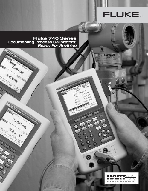
It’s easy to calibrate and maintain HART instrumentation with one powerful tool.With the 744 DPC, you can:• Generate precision electrical, temperature, orpressure signals for analog stimulus or sensorsimulation.• Simultaneously measure electrical, temperature, orpressure signals from transmitter output.• Determine type, manufacturer, model, tag ID byinterrogating HART devices.• Read HART PV function and smart transmitter digitaloutput while measuring analog mA output.• Read and write HART configuration functions tomake field adjustments to PV range points, damping,and other top-level configuration settings.• Change sensor configuration on supportedtemperature transmitters.• Re-label smart transmitters by reading and writingHART tag and message fields.• Clone additional transmitters by reading andstoring basic HART configurations.• Perform automated HART sensor trim and outputtrim for selected devices in conjunction with AsFound/As Left tests.• Perform loop test with simultaneous analog anddigital mA readout.• Address new, fast, pulsed-excitation smart transmittersand PLCs.• Control Hart Scientific Dry Block Calibrator.4 <strong>Fluke</strong> Corporation <strong>740</strong> <strong>Series</strong> Brochure
Why use “smart” instrumentation?Like most process plants, your organization is probablyfacing the dual challenges of maximizing productivitywhile minimizing maintenance costs. “Smart” digitaltransmitters offer superior performance and reliability,while saving time and effort in maintenance andcalibration. Manufacturers of field instruments havehelped accelerate the changeover by offering smarttransmitters at prices nearly as low as analog units.As digital instruments using the HART protocol quicklybecome the standard, communicators and calibratorsare becoming essential everyday tools.What is HART?HART, the Highway Addressable Remote Transducerprotocol, uses a 1200 baud Frequency Shift Keying(FSK) signal to superimpose digital information on theconventional 4-20 mA analog signal.Why use the HART protocol?HART is an industry standard developed to define thecommunications protocol between intelligent fielddevices and a control system, HART is the most widelyused digital communication protocol in the processindustry. More than five million HART field instrumentsare installed in more than 100,000 plants worldwide.The HART protocol:• Is supported by all of the major suppliers of processfield instruments supported by the HART CommunicationFoundation, an industry-wide non-profitorganization. See the Web site HYPERLINKhttp://www.hartcomm.org for information on theHART standard.• Preserves present control strategies.• Allows traditional 4-20 mA signals and digitalcommunication to share the same two-wire loops.• Provides important information for installation andmaintenance: Tag IDs, measured values, range andspan data, product information and diagnostics.• Reduces operation costs by making it easierto manage and fully utilize “smart” instrumentnetworks.<strong>Fluke</strong> 789ProcessMeter The <strong>Fluke</strong>-789 extends the proven performance of theevolutionary <strong>Fluke</strong>-787 and adds many new featuresand improvements.Key New 789 features:• 24 V loop power supply• HART mode setting with loop power(adds 250 ohm resistor)• 200 % larger dual display• mA drive up to 1,200 ohms• Enhanced backlight with (2) brightness settings• Improved battery power with (4) AA batteries• 0 to 100 % mA Span Check buttons to toggle from4 mA to 20 mA• Infrared I/O serial port compatible with <strong>Fluke</strong>ViewSoftware• 5 V measurement capability on the 4 V range forprecise 1 V to 5 V measurements787 features included in the 789:• DMM designed to meet 1000 V IEC 1010 CAT IIIstandards• Precision 1000 V, 400 mA digital multimeterMeasure ac and dc volts,ac and dc current, resistance, continuity and frequencyTrue-rms ac voltage measurementFrequency measurement to 20 kHz• 20 mA dc current source/loop calibrator/simulatorManual Step (100 %, 25 %, Coarse, Fine) plusAuto Step and Auto Ramp• Externally accessible battery for easy battery changes• V overload protection on V, ohms, frequency, mA(backed up by 440 mA 1000 V fuse)6 <strong>Fluke</strong> Corporation <strong>740</strong> <strong>Series</strong> Brochure
Measurement Function SpecificationsDC voltage measurementAccuracy (% of reading + % of full scale)Range (full scale) 1 year 2 years110.000 mV 0.025 % + 0.015 % 0.05 % + 0.015 %1.10000 V 0.025 % + 0.005 % 0.05 % + 0.005 %11.0000 V 0.025 % + 0.005 % 0.05 % + 0.005 %110.000 V 0.05 % + 0.005 % 0.1 % + 0.005 %300.00 V 0.05 % + 0.005 % 0.1 % + 0.005 %Temperature coefficient: (0.001 % reading + 0.0015 % f.s.)/°Cfrom -10 °C to 18 °C and 28 °C to 50 °CInput impedance: 5 MΩCommon mode error: 0.008 % f.s./(Common Mode Volt)Maximum input voltage: 300 V rmsAC voltage measurementAccuracy (% of reading + counts)Frequency range 1 year 2 years20 Hz to 40 Hz 2 % + 10 2 % + 1040 Hz to 500 Hz 0.5 % + 5 0.5 % + 5500 Hz to 1 kHz 2 % + 10 2 % + 101 kHz to 5 kHz 10 % + 20 10 % + 20Ranges: 1.1000 V, 11.000 V, 110.00 V, 300.0 VSpecifications apply for 10 % to 100 % of rangeInput impedance: 5 MΩ and 400 ΩFrequency measurementAccuracyRange 1 year 2 years1.00 Hz to 109.99 Hz 0.05 Hz 0.05 Hz110.0 Hz to 1099.9 Hz 0.5 Hz 0.5 Hz1.100 kHz to 10.999 kHz 0.005 kHz 0.005 kHz11.00 kHz to 50.00 kHz 0.05 kHz 0.05 kHzFor frequencies < 109.99 Hz, specification applies for signals withslew rates > 5 V/msMinimum amplitude for Hz measurement: (Squarewaves) 1 Hz to1 kHz, 300 mV p-p; 1 kHz to 30 kHz, 1.4 V p-p; > 30 kHz, 2.8 V p-pMaximum input: 1 Hz to 1 kHz, 300 V rms; > 1 kHz, 30 V rmsInput impedance: 5 MΩSourcing (Simulation) Function SpecificationsDC voltage outputAccuracy (% of output + % of full scale)Range (full scale) 1 year 2 years110.000 mV 0.01 % + 0.005 % 0.015 % + 0.005 %1.10000 V 0.01 % + 0.005 % 0.015 % + 0.005 %15.0000 V 0.01 % + 0.005 % 0.015 % + 0.005 %Temperature coefficient: (0.001 % output + 0.001 % f.s.)/°Cfrom -10 °C to 18 °C and 28 °C to 50 °CMaximum output current: 10 mALoading: (0.001 % f.s. +1 µV)/mACommon mode error: 0.008 % f.s./(Common Mode Volt)Maximum input voltage: 30 V dcDC current outputAccuracy (% of output + % of full scale)Range (full scale) 1 year 2 years22.000 mA 0.01 % + 0.015 % 0.02 % + 0.015 %Current sink (sim- 0.02 % + 0.03 % 0.02 % + 0.03 %ulate transmitter)Specification applies from 2 to 22 mA; below 2 mA typical accuracy is0.15 % of full scaleMaximum burden voltage: 24 VTemperature coefficient: (0.003 % output + 0.003 % f.s.)/°Cfrom -10 °C to 18 °C and 28 °C to 50 °CCommon mode error: 0.008 % f.s./(Common Mode Volt)Maximum input voltage: 30 V dcResistance sourcingAccuracy (% of output + ohms)Range (full scale) 1 year 2 years11.000 Ω 0.01 % + 20 mΩ 0.02 % + 20 mΩ110.00 Ω 0.01 % + 40 mΩ 0.02 % + 40 mΩ1.1000 kΩ 0.02 % + 0.5 Ω 0.03 % + 0.5 Ω11.000 kΩ 0.03 % + 5 Ω 0.04 % + 5 ΩTemperature coefficient: 0.01 % f.s./°C from -10 °C to 18 °C and28 °C to 50 °CMaximum and minimum current through source resistance:Maximum Minimum11 Ω range: 3 mA dc 0.1 mA dc110 Ω range: 3 mA dc 0.1 mA dc1.1 kΩ range: 3 mA dc 0.01 mA dc11 kΩ range: 1 mA dc 0.01 mA dcCommon mode error: 0.008 % f.s./(Common Mode Volt)Maximum input voltage: 30 V dcFrequency sourcingAccuracyRange 1 year 2 years0.00 to 10.99 Hz 0.01 Hz 0.01 Hz11.00 Hz to 109.99 Hz 0.1 Hz 0.1 Hz110.0 Hz to 1099.9 Hz 0.1 Hz 0.1 Hz1.100 kHz to 21.999 kHz 0.002 kHz 0.002 kHz22.000 kHz to 50.000 kHz 0.005 kHz 0.005 kHzWaveforms: Squarewave with 50 % duty cycle, sinewaveAmplitude: 0.1 to 10 V p-pAmplitude accuracy: 3 % of output + 0.5 % of f.s., 1 to 1099 Hz;10 % of output + 0.5 % of f.s., 1.1 to 10.9 kHz; 30 % of output +0.5 % f.s., 11 to 50 kHzMaximum input voltage: 30 V dc8 <strong>Fluke</strong> Corporation <strong>740</strong> <strong>Series</strong> Brochure
Temperature Measurement andSimulation SpecificationsTemperature, RTDsAnalyzing specifications can be complex.To get a true picture of calibratorperformance, you should be aware ofthe key components of a specificationand how to interpret them. Specificationsmust be carefully consideredwhen comparing calibrators fromdifferent vendors. The most importantcomponents of a process calibratorspecification are:• Reference uncertainty. Performanceof a calibrator at 23 °C + 3°C at thetime it is verified by the manufacturer.This specification does notinclude the effects of time andtemperature, two of the largest componentsof calibrator error.• Time. <strong>Fluke</strong> <strong>740</strong> <strong>Series</strong> calibratorsare delivered with both one-yearand two-year specs, to limit yourcalibration support costs. You chooseyour cal interval based upon theperformance you need.AccuracyMeasureSourceType and range 1 year 2 years 1 year 2 years10 Ω Cu (427)-100 to 0 °C 2 °C 2 °C 1 °C 1 °C0 to 260 °C 2 °C 2 °C 1 °C 1 °C100 Ω Pt (3916)-200 to -190 °C 0.3 °C 0.4 °C 0.3 °C 0.4 °C-190 to 0 °C 0.3 °C 0.4 °C 0.1 °C 0.2 °C0 to 630 °C 0.5 °C 0.8 °C 0.2 °C 0.4 °C100 Ω Pt (3926)-200 to 0 °C 0.3 °C 0.4 °C 0.1 °C 0.2 °C0 to 630 °C 0.5 °C 0.8 °C 0.2 °C 0.4 °C100 Ω Pt (385)-200 to 0 °C 0.3 °C 0.5 °C 0.1 °C 0.2 °C0 to 400 °C 0.5 °C 0.8 °C 0.2 °C 0.4 °C400 to 800 °C 0.8 °C 1.0 °C 0.4 °C 0.5 °C200 Ω Pt (385)-200 to 0 °C 0.3 °C 0.5 °C 0.1 °C 0.2 °C0 to 400 °C 0.5 °C 0.8 °C 0.2 °C 0.4 °C400 to 630 °C 0.8 °C 1.0 °C 0.4 °C 0.5 °C500 Ω Pt (385)-200 to 0 °C 0.3 °C 0.5 °C 0.1 °C 0.2 °C0 to 400 °C 0.5 °C 0.8 °C 0.2 °C 0.4 °C400 to 630 °C 0.8 °C 1.0 °C 0.4 °C 0.5 °C1000 Ω Pt (385)-200 to 0 °C 0.3 °C 0.5 °C 0.1 °C 0.2 °C0 to 400 °C 0.5 °C 0.8 °C 0.2 °C 0.4 °C400 to 630 °C 0.8 °C 1.0 °C 0.4 °C 0.5 °C120 Ω Ni (672)-80 to 260 °C 0.3 °C 0.4 °C 0.1 °C 0.2 °CFor 2-wire and 3-wire measurements add 0.4 °CSensor inaccuracies not includedResolution: 0.1 °C, except 1 °C for 10 Ω CuTemperature coefficient: 0.02 °C/°C from -10 °C to 18 °C and28 °C to 50 °CMaximum input voltage: 30 V dcMaximum input current for RTD Source function:10 Ω RTD 8 mA dc100, 120 Ω RTDs 8 mA dc*200, 500, 1000 Ω RTDs 1 mA dc741B*, 743B*, 744: Addresses pulsed transmitters and PLCs withpulses as short as 1 ms* For 741B serial number 7935XXXX and greater.For 743B serial number 7940XXXX and greater.Otherwise, 3 mA and 100 ms.How to compare calibrators based on specifications.9 <strong>Fluke</strong> Corporation <strong>740</strong> <strong>Series</strong> Brochure• Temperature. <strong>Fluke</strong> process calibratorspecs reflect performance from18 ° to 28 °C. Compensation factorsare provided to permit specified useof the calibrators over a wide -10 ° to50 °C range.• Allowance for traceability. <strong>Fluke</strong>specs are not relative specs, but totalspecs, including an allowance foruncertainty of standards that providetraceability to national standards.• Confidence level. <strong>Fluke</strong> uses a conservative95 % confidence level whensetting specifications, increasing yourconfidence that your calibrator willremain in spec for its stated calibrationinterval.For more information, refer to the applicationnote “Understanding Specifications For ProcessCalibrators.”Temperature, ThermocouplesAccuracyMeasureSourceType and range 1 year 2 years 1 year 2 yearsE-250 to -200 °C 1.3 °C 2.0 °C 0.6 °C 0.9 °C-200 to -100 °C 0.5 °C 0.8 °C 0.3 °C 0.4 °C-100 to 600 °C 0.3 °C 0.4 °C 0.3 °C 0.4 °C600 to 1000 °C 0.4 °C 0.6 °C 0.2 °C 0.3 °CN-200 to -100 °C 1.0 °C 1.5 °C 0.6 °C 0.9 °C-100 to 900 °C 0.5 °C 0.8 °C 0.5 °C 0.8 °C900 to 1300 °C 0.6 °C 0.9 °C 0.3 °C 0.4 °CJ-210 to -100 °C 0.6 °C 0.9 °C 0.3 °C 0.4 °C-100 to 800 °C 0.3 °C 0.4 °C 0.2 °C 0.3 °C800 to 1200 °C 0.5 °C 0.8 °C 0.2 °C 0.3 °CL-200 to -100 °C 0.6 °C 0.9 °C 0.3 °C 0.4 °C-100 to 800 °C 0.3 °C 0.4 °C 0.2 °C 0.3 °C800 to 900 °C 0.5 °C 0.8 °C 0.2 °C 0.3 °CK-200 to -100 °C 0.7 °C 1.0 °C 0.4 °C 0.6 °C-100 to 400 °C 0.3 °C 0.4 °C 0.3 °C 0.4 °C400 to 1200 °C 0.5 °C 0.8 °C 0.3 °C 0.4 °C1200 to 1372 °C 0.7 °C 1.0 °C 0.3 °C 0.4 °CT-250 to -200 °C 1.7 °C 2.5 °C 0.9 °C 1.4 °C-200 to 0 °C 0.6 °C 0.9 °C 0.4 °C 0.6 °C0 to 400 °C 0.3 °C 0.4 °C 0.3 °C 0.4 °CU-200 to 0 °C 0.6 °C 0.9 °C 0.4 °C 0.6 °C0 to 600 °C 0.3 °C 0.4 °C 0.3 °C 0.4 °CB600 to 800 °C 1.3 °C 2.0 °C 1.0 °C 1.5 °C800 to 1000 °C 1.0 °C 1.5 °C 0.8 °C 1.2 °C1000 to 1820 °C 0.9 °C 1.3 °C 0.8 °C 1.2 °CR-20 to 0 °C 2.3 °C 2.8 °C 1.2 °C 1.8 °C0 to 100 °C 1.5 °C 2.2 °C 1.1 °C 1.7 °C100 to 1767 °C 1.0 °C 1.5 °C 0.9 °C 1.4 °CS-20 to 0 °C 2.3 °C 2.8 °C 1.2 °C 1.8 °C0 to 200 °C 1.5 °C 2.1 °C 1.1 °C 1.7 °C200 to 1400 °C 0.9 °C 1.4 °C 0.9 °C 1.4 °C1400 to 1767 °C 1.1 °C 1.7 °C 1.0 °C 1.5 °CC0 to 800 °C 0.6 °C 0.9 °C 0.6 °C 0.9 °C800 to 1200 °C 0.8 °C 1.2 °C 0.7 °C 1.0 °C1200 to 1800 °C 1.1 °C 1.6 °C 0.9 °C 1.4 °C1800 to 2316 °C 2.0 °C 3.0 °C 1.3 °C 2.0 °CXK-200 to -100 °C 0.5 °C 0.7 °C 0.4 °C 0.5 °C-100 to 800 °C 0.4 °C 0.6 °C 0.3 °C 0.4 °CBP0 to 800 °C 0.8 °C 1.1 °C 0.4 °C 0.5 °C800 to 1600 °C 1.2 °C 1.8 °C 0.5 °C 0.8 °C600 to 2500 °C 2.2 °C 3.3 °C 0.9 °C 1.4 °CSensor inaccuracies not includedAccuracy with external cold junction; for internal junction add 0.2 °CResolution: 0.1 °CTemperature scale: ITS-90 or IPTS-68, selectableCompensation: ITS-90 per NIST Monograph 175 for E, N, J, K, T, B, R,S thermocouples; IPTS-68 per IEC 584-1 for E, J, K, T, B, R, S thermocouples;IPTS-68 per DIN 43710 for L, U thermocouplesTemperature coefficient: 0.05 °C/°C from -10 °C to 18 °C and28 °C to 50 °CCommon mode error: 0.01 °C/(Common Mode Volt)Maximum input voltage: 30 V dcNote: When simulating temperature in As Found/As Left procedures,steps may be either linear by temperature or linear by mV potential.
Pressure SpecificationsThe <strong>Fluke</strong> family of 29 pressure modules:Covers virtually any pressure application includinggage, differential, dual (compound), absolute, andvacuum.• Display pressure readings in any of 10 differentpressure units you specify in the calibrator setup.• Rugged urethane molded cases protect the modulesfrom rough handling and harsh conditions.• Features internal temperature compensation fromO° to 50 °C for full-accuracy performance.• Includes NIST-traceable calibration certificate.• Modules can be calibrated locally, helping tocontrol costs.Pressure module specifications (all specifications in % of full span. Specifications reflect a confidence interval of 95%.)Reference High 2 Low 2 Max over-Range/ Range (approx)/ uncertainty Stability Temperature Total 1 side side Fitting pressureModel Resolution Resolution (23 ± 3 ºC) (1 year) (0 to 50 ºC) uncertainty media media material (x nominal)DifferentialFLUKE-700P00 1 in. H 2 O/0.001 0.25 kPa/0.0002 0.300 0.025 0.025 0.350 Dry Dry 316 SS 30xFLUKE-700P01 10 in. H 2 O/0.01 2.5 kPa/0.002 0.200 0.050 0.050 0.300 Dry Dry 316 SS 3xFLUKE-700P02 1 psi/0.0001 6900 Pa/0.7 0.150 0.070 0.080 0.300 Dry Dry 316 SS 3xFLUKE-700P22 1 psi/0.0001 6900 Pa/0.7 0.100 0.020 0.030 0.150 316 SS Dry 316 SS 3xFLUKE-700P03 5 psi/0.0001 34 kPa/0.001 0.050 0.020 0.030 0.100 Dry Dry 316 SS 3xFLUKE-700P23 5 psi/0.0001 34 kPa/0.001 0.025 0.010 0.015 0.050 316 SS Dry 316 SS 3xFLUKE-700P04 15 psi/0.001 103 kPa/0.01 0.025 0.010 0.015 0.050 Dry Dry 316 SS 3xFLUKE-700P24 15 psi/0.001 103 kPa/0.01 0.025 0.010 0.015 0.050 316 SS Dry 316 SS 3xGageFLUKE-700P05 30 psi/0.001 207 kPa/0.01 0.025 0.010 0.015 0.050 316 SS N/A 316 SS 3xFLUKE-700P06 100 psi/0.01 690 kPa/0.07 0.025 0.010 0.015 0.050 316 SS N/A 316 SS 3xFLUKE-700P27 300 psi / 0.01 2070 kPa / 0.1 0.025 0.010 0.015 0.050 316 SS N/A 316 SS 3xFLUKE-700P07 500 psi/0.01 3400 kPa/0.1 0.025 0.010 0.015 0.050 316 SS N/A 316 SS 3xFLUKE-700P08 1000 psi/0.1 6900 kPa/0.7 0.025 0.010 0.015 0.050 316 SS N/A 316 SS 3xFLUKE-700P09 1500 psi/0.1 10 MPa/0.001 0.025 0.010 0.015 0.050 316 SS N/A 316 SS 2xAbsolute (not compatible with <strong>Fluke</strong> 701 or 702)FLUKE-700PA3 5 psi/0.0001 34 kPa/0.001 0.050 0.010 0.010 0.070 316 SS N/A 316 SS 3xFLUKE-700PA4 15 psi/0.001 103 kPa/0.01 0.050 0.010 0.010 0.070 316 SS N/A 316 SS 3xFLUKE-700PA5 30 psi/0.001 207 kPa/0.01 0.050 0.010 0.010 0.070 316 SS N/A 316 SS 3xFLUKE-700PA6 100 psi/0.01 690 kPa/0.07 0.050 0.010 0.010 0.070 316 SS N/A 316 SS 3xVacuum (not compatible with <strong>Fluke</strong> 701 or 702)FLUKE-700PV3 -5 psi/0.0001 -34 kPa/0.001 0.040 0.015 0.015 0.070 316 SS Dry 316 SS 3xFLUKE-700PV4 -15 psi/0.001 -103 kPa/0.01 0.040 0.015 0.015 0.070 316 SS Dry 316 SS 3xDualFLUKE-700PD2 ±1 psi/0.0001 ±6900 Pa/0.7 0.150 0.025 0.025 0.200 316 SS Dry 316 SS 3xFLUKE-700PD3 ±5 psi/0.0001 ±34 kPa/0.001 0.040 0.015 0.015 0.070 316 SS Dry 316 SS 3xFLUKE-700PD4 ±15 psi/0.001 ±103 kPa/0.01 0.025 0.010 0.015 0.050 316 SS Dry 316 SS 3xFLUKE-700PD5 -15/30 psi/0.001 -100/207 kPa/0.01 0.025 0.010 0.015 0.050 316 SS N/A 316 SS 3xFLUKE-700PD6 -15/100 psi/0.01 -100/690 kPa/0.07 0.025 0.010 0.015 0.050 316 SS N/A 316 SS 3xFLUKE-700PD7 -15/200 psi/0.01 -100/1380 kPa/0.1 0.040 0.015 0.015 0.070 316 SS N/A 316 SS 3xHighFLUKE-700P29 3000 psi/0.1 20.7 M Pa/0.001 0.050 0.010 0.020 0.080 C276 N/A C276 2xFLUKE-700P30 5000 psi/0.1 34 M Pa/0.001 0.050 0.010 0.020 0.080 C276 N/A C276 2xFLUKE-700P31 10000 psi/1 69 M Pa/0.007 0.050 0.010 0.020 0.080 C276 N/A C276 1.5x1Total uncertainty, one year for temperature range 0 °C to +50 °C. Total uncertainty, 1.0% of full span for temperature range -10 °C to 0 °C. For P00 module only, compensatedtemperature range is 15 ° to 35 °C.2“Dry” indicates dry air or non-corrosive gas as compatible media. “316 SS” indicates media compatible with Type 316 Stainless Steel. “C276” indicates media compatible withHastelloy C276.Use of pressure zero is required prior to measurement or source. Maximum overpressure specification includes common mode pressure. Modules are rated. Metric adapter(s):1/4˝ NPT female to male BSP/ISO 1/4-19, tapered thread, included with all modules except P29, P30, and P31. Effective October 1996, all modules include a NIST traceable certificateand test data.10 <strong>Fluke</strong> Corporation <strong>740</strong> <strong>Series</strong> Brochure
General SpecificationsData log function (except 741B)Measure functions: Voltage, current, resistance,frequency, temperature, pressureReading rate: 1, 2, 5, 10, 20, 30, or 60 readings perminuteMaximum record length: 8000 readings(7980 for 30 or 60 readings per minute)Ramp functionSource functions: Voltage, current, resistance,frequency, temperatureRate: 4 steps/secondTrip detect: Continuity* or voltage*Continuity detection not available when sourcing currentLoop power functionVoltage: Selectable, 24 V or 28 VAccuracy: 5 %Maximum current: 22 mA, short-circuit protectedMaximum input voltage: 30 V dcNote: 250 Ω series resistance is automatically supplied whenever loop power isenabled on 744.HART modem interface (744 only)Maximum input voltage: 30 V dcEnvironmental specificationsAll calibrator specifications apply from +18 °C to+28 °C unless stated otherwise.Operating temperature: -10 °C to 50 °C, (-20 °C typicalexcept for frequency and ac voltage measurement)Storage temperature: -20 °C to 60 °COperating altitude: 2800 m above mean sea level(9186 ft)90-day specifications: The standard specificationintervals for the <strong>740</strong> <strong>Series</strong> are 1 and 2 years. Typical90-day measurement and source accuracy can beestimated by dividing the one year “% of reading” or“% of output” specifications by 2. Floor specifications,expressed as “% of f.s.” or “counts” or “ohms” remainconstant.Power: Internal battery pack NiCd, 7.2 V, 1700 mAh;NiMH (744 only) 7.2 V, 3500 mAhBattery Life: Typical usage, >8 hoursDimensions: 130 mm x 236 mm x 61 mm(5.1 in x 9.3 in x 2.4 in)Weight: 1.4 kg (3 lb, 1 oz)Side Port Connections:• Pressure module connector• RS-232 connector (743B and 744) to interface toyour PC• Connection for optional battery eliminatorSafety: Complies with CAN/CSA C22.2 No 1010.1-92,ANSI/ISA S82.01-1994, UL3111, and EN610-1:1993.Data Storage Capacity:<strong>Fluke</strong> 741B—1 day of calibration results<strong>Fluke</strong> 743B and 744—1 week of calibration resultsOrdering InformationFLUKE-741B Documenting Process CalibratorFLUKE-743B Documenting Process CalibratorFLUKE-744 Documenting Process Calibrator-HARTIncluded with the <strong>Fluke</strong> <strong>740</strong> <strong>Series</strong>:Type TL224 Industrial <strong>Test</strong> Leads (two sets), AC220<strong>Test</strong> Clips (2 sets), TP220 <strong>Test</strong> Probes (1 set), BatteryPack, Battery Charger, serial port cable (except 741B),HART communications cable (744 only), DPC/TRACKSample with free PC communication utility software(except 741B), Instruction Manual, NIST-traceable calibrationreport and data, three-year warranty.FLUKE-700SW DPC/TRACK Software (for use withModel 743B or 744 calibrators)Included with DPC/TRACK software:Software media, Instruction Manual, Serial Port Cable,DB9 to DB25 (9 pin to 25 pin) Adapter.FLUKE-700 Pxx Pressure ModulesIncluded with each <strong>Fluke</strong> Pressure Module:BP-ISO Adapter(s) (except with P29 - P31), InstructionSheet, NIST traceable calibration report and data,one-year warranty.FLUKE-744 Upgrade<strong>Fluke</strong>-744V20 HART Upgrade Revision 2.5Accessories<strong>Fluke</strong>-700PMP Pressure Pump; 100 psi/7 bar<strong>Fluke</strong>-700LTP-1 Low Pressure <strong>Test</strong> Pump<strong>Fluke</strong>-700PTP-1 Pneumatic <strong>Test</strong> Pump;400 psi/40 bar<strong>Fluke</strong>-700HTP-1 Hydraulic <strong>Test</strong> Pump;10,000 psi/700 bar<strong>Fluke</strong>-700HTH-1 Hydraulic <strong>Test</strong> Hose<strong>Fluke</strong>-700PRV-1 Pressure Relief Valve Kit for HTP<strong>Fluke</strong>-700-IV Current Shunt (for mA/mAapplications)<strong>Fluke</strong>-700PCK Pressure Calibration Kit<strong>Fluke</strong>-700BCW Bar Code Wand<strong>Fluke</strong>-700TC1 TC Mini-Plug Kit, 9 types<strong>Fluke</strong>-700TC2 TC Mini-Plug Kit, JKTERS80T-IRInfrared Probe80PK-IRInfrared ProbeBE9005Battery EliminatorBC7217Battery ChargerBP7217NiCd Battery PackBP7235NiMH Battery PackC700Hard Carrying CaseC781Soft Carrying CaseC789Soft Carrying CaseC75<strong>Test</strong> Lead Case<strong>Fluke</strong>. Keeping your world up and running.®<strong>Fluke</strong> CorporationPO Box 9090,Everett, WA 98206 U.S.A.<strong>Fluke</strong> Europe B.V.PO Box 1186, 5602 BDEindhoven, The Netherlands©2004-2008 <strong>Fluke</strong> Corporation. Specifications subject to change withoutnotice. Printed in U.S.A. 6/2008 1263323 B-EN-N Rev JModification of this document is not permitted without written permissionfrom <strong>Fluke</strong> Corporation.11 <strong>Fluke</strong> Corporation <strong>740</strong> <strong>Series</strong> Brochure