G) Tektronix scope spec sheet.pdf - MicroBooNE Document Database
G) Tektronix scope spec sheet.pdf - MicroBooNE Document Database
G) Tektronix scope spec sheet.pdf - MicroBooNE Document Database

You also want an ePaper? Increase the reach of your titles
YUMPU automatically turns print PDFs into web optimized ePapers that Google loves.
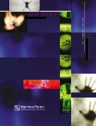
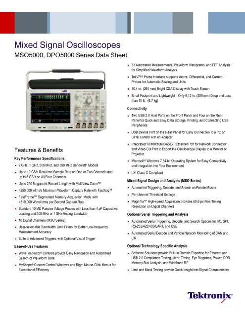
Mixed Signal Oscillo<strong>scope</strong>sMSO5000, DPO5000 Series Data Sheet53 Automated Measurements, Waveform Histograms, and FFT Analysisfor Simplified Waveform AnalysisTekVPI ® Probe Interface supports Active, Differential, and CurrentProbes for Automatic Scaling and Units10.4 in. (264 mm) Bright XGA Display with Touch ScreenSmall Footprint and Lightweight – Only 8.12 in. (206 mm) Deep and Lessthan 15 lb. (6.7 kg)Features & BenefitsKey Performance Specifications2 GHz, 1 GHz, 500 MHz, and 350 MHz Bandwidth ModelsUp to 10 GS/s Real-time Sample Rate on One or Two Channels andup to 5 GS/s on All Four ChannelsUp to 250 Megapoint Record Length with MultiView Zoom>250,000 wfms/s Maximum Waveform Capture Rate with FastAcqFastFrame Segmented Memory Acquisition Mode with>310,000 Waveforms per Second Capture RateStandard 10 MΩ Passive Voltage Probes with Less than 4 pF CapacitiveLoading and 500 MHz or 1 GHz Analog Bandwidth16 Digital Channels (MSO Series)User-selectable Bandwidth Limit Filters for Better Low-frequencyMeasurement AccuracySuite of Advanced Triggers, with Optional Visual TriggerEase-of-Use FeaturesWave In<strong>spec</strong>tor ® Controls provide Easy Navigation and AutomatedSearch of Waveform DataMyScope ® Custom Control Windows and Right Mouse Click Menus forExceptional EfficiencyConnectivityTwoUSB2.0Host Ports on the Front Panel and Four on the RearPanel for Quick and Easy Data Storage, Printing, and Connecting USBPeripheralsUSB Device Port on the Rear Panel for Easy Connection to a PC orGPIB Control with an AdapterIntegrated 10/100/1000BASE-T Ethernet Port for Network Connectionand Video Out Port to Export the Oscillo<strong>scope</strong> Display to a Monitor orProjectorMicrosoft ® Windows 7 64-bit Operating System for Easy Connectivityand Integration into Your EnvironmentLXI Class C CompliantMixed Signal Design and Analysis (MSO Series)Automated Triggering, Decode, and Search on Parallel BusesPer-channel Threshold SettingsMagniVu High-speed Acquisition provides 60.6 ps Fine TimingResolution on Digital ChannelsOptional Serial Triggering and AnalysisAutomated Serial Triggering, Decode, and Search Options for I 2 C, SPI,RS-232/422/485/UART, and USBAutomated Serial Decode and Vehicle Network Monitoring of CAN andLINOptional Technology Specific AnalysisSoftware Solutions provide Built-in Domain Expertise for Ethernet andUSB 2.0 Compliance Testing, Jitter, Timing, Eye Diagrams, Power, DDRMemory Bus Analysis, and Wideband RFLimit and Mask Testing provide Quick Insight into Signal Characteristics
Data Sheetall channels and an optional record length of up to 250M points on twochannels.With Wave In<strong>spec</strong>tor ® controls for rapid waveform navigation, and morethan 10 optional software and analysis packages for common technologiesand in-depth analysis tasks, the MSO/DPO5000 Series from <strong>Tektronix</strong>provides the feature-rich tools you need to simplify and speed debug ofyour complex design.Comprehensive Features Speed Every Stageof DebugThe MSO/DPO5000 Series offers a robust set of features to speed everystage of debugging your design – from quickly discovering an anomaly andcapturing it, to searching your waveform record for the event and analyzingits characteristics and your device's behavior.Discover – Fast waveform capture rate - over 250,000 wfm/s - maximizes the probabilityof capturing elusive glitches and other infrequent events.Feature-rich Tools for Debugging MixedSignal DesignsWith the MSO/DPO5000 Mixed Signal Oscillo<strong>scope</strong> Series, you cananalyze up to 20 analog and digital signals with a single instrument toquickly find and diagnose problems in complex designs. Bandwidths up to2 GHz and sample rates up to 10 GS/s ensure you have the performanceyou need to see fast-changing signal details. To capture long windows ofsignal activity while maintaining fine timing resolution, the MSO/DPO5000Series offers a deep record length of up to 12.5M points standard onDiscoverTo debug a design problem, first you must know it exists. Everydesign engineer spends time looking for problems in their design, atime-consuming and frustrating task without the right debug tools.The MSO/DPO5000 Series offers the industry's most complete visualizationof signals, providing fast insight into the real operation of your device.<strong>Tektronix</strong> proprietary FastAcq technology delivers a fast waveformcapture – greater than 250,000 waveforms per second – that enables you tosee glitches and other infrequent transients within seconds, revealing thetrue nature of device faults. A digital phosphor display with color intensitygrading shows the history of a signal's activity by using color to identifyareas of the signal that occur more frequently, providing a visual displayof just how often anomalies occur.2 www.tektronix.com
Mixed Signal Oscillo<strong>scope</strong>s — MSO5000, DPO5000 SeriesCapture – Triggering on a <strong>spec</strong>ific transmit data packet going across an RS-232 bus. Acomplete set of triggers, including triggers for <strong>spec</strong>ific serial packet content, ensures youquickly capture your event of interest.CaptureDiscovering a device fault is only the first step. Next, you must capture theevent of interest to identify root cause.Accurately capturing any signal of interest begins with proper probing. TheMSO/DPO5000 Series includes four high-impedance low-capacitanceprobes for accurate signal capture. These industry-first high-impedancepassive voltage probes have less than 4 pF of capacitive loading tominimize the effect of the probe on your circuit's operation, offering theperformance of an active probe with the flexibility of a passive probe.The MSO/DPO5000 Series provides a complete set of triggers – includingrunt, glitch, width, timeout, transition, pattern, state, setup/hold violation,serial packet, and parallel data – to help quickly find your event. EnhancedTriggering reduces trigger jitter at the trigger point. In this mode, the triggerpoint can be used as a measurement reference.Finding the right characteristic of a complex signal can require hours ofcollecting and sorting through thousands of acquisitions for the event ofinterest. Defining a trigger that isolates the desired event and shows dataonly when the event occurs speeds up this process. The optional VisualTrigger makes the identification of the desired waveform events quick andeasy by scanning through all waveform acquisitions and comparing them toon-screen areas (geometric shapes).With up to a 250M point record length, you can capture many events ofinterest, even thousands of serial packets, in a single acquisition for furtheranalysis while maintaining high resolution to zoom in on fine signal details.Investigate multiple segments of your waveform capture simultaneouslywith MultiView Zoom to quickly compare events in real time. FastFrameSegmented Memory mode enables you to make efficient use of largerecords by capturing many trigger events in a single record eliminating largetime gaps between events of interest. View and measure the segmentsindividually or as an overlay.Search – Results of an advanced search for a runt pulse or a narrow glitch within a longwaveform record. Each instance of the runt or glitch is automatically marked for easyreference. Wave In<strong>spec</strong>tor controls provide unprecedented efficiency in viewing andnavigating waveform data.From triggering on <strong>spec</strong>ific packet content to automatic decode in multipledata formats, the MSO/DPO5000 Series provides integrated support for abroad range of serial buses – I 2 C, SPI, RS-232/422/485/UART, and USB.The ability to decode up to 16 serial and/or parallel buses simultaneouslymeans you gain insight into system-level problems quickly.To further help troubleshoot system-level interactions in complex embeddedsystems, the MSO5000 Series offers 16 digital channels in addition toits analog channels. Since the digital channels are fully integrated intothe oscillo<strong>scope</strong>, you can trigger across all input channels, automaticallytime correlating all analog, digital, and serial signals. The MagniVuhigh-speed acquisition enables you to acquire fine signal detail (up to60.6 ps resolution) around the trigger point for precision measurements.MagniVu is essential for making accurate timing measurements for setupand hold, clock delay, signal skew, and glitch characterization.SearchFinding your event of interest in a long waveform record can be timeconsuming without the right search tools. With today's record lengthspushing beyond a million data points, locating your event can mean scrollingthrough thousands of screens of signal activity.The MSO/DPO5000 Series offers the industry's most comprehensivesearch and waveform navigation with its innovative Wave In<strong>spec</strong>tor ®controls. These controls speed panning and zooming through your record.With a unique force-feedback system, you can move from one end of yourrecord to the other in just seconds. User marks allow you to mark anylocation that you may want to reference later for further investigation. Or,automatically search your record for criteria you define. Wave In<strong>spec</strong>tor willinstantly search your entire record, including analog, digital, and bus data.Along the way it will automatically mark every occurrence of your definedevent so you can quickly move between events. The standard AdvancedSearch and Mark capability of the MSO/DPO5000 Series can even searchfor up to eight different events simultaneously and stop a live acquisitionwhen it finds an event of interest, saving even more time.www.tektronix.com 3
Data SheetAnalyze – Waveform histogram of a falling edge showing the distribution of edge position(jitter) over time. Included are numeric measurements made on the waveform histogramdata. A comprehensive set of integrated analysis tools speeds verification of your design'sperformance.AnalyzeVerifying that your prototype's performance matches simulations and meetsthe project's design goals requires analyzing its behavior. Tasks canrange from simple checks of rise times and pulse widths to sophisticatedpower loss analysis, characterization of system clocks, and investigation ofnoise sources. The MSO/DPO5000 Series offers a comprehensive set ofintegrated analysis tools including waveform- and screen-based cursors, 53automated measurements, advanced waveform math including arbitraryequation editing, waveform histograms, and FFT analysis.Every MSO/DPO5000 Series oscillo<strong>scope</strong> includes the DPOJETEssentials jitter and eye pattern analysis software package, extending theoscillo<strong>scope</strong>'s measurement capabilities to make measurements overcontiguous clock and data cycles in a single-shot real-time acquisition. Thisenables measurement of key jitter and timing analysis parameters such asTime Interval Error and Phase Noise to help characterize possible systemtiming issues. Analysis tools such as plots for time trends and histogramsquickly show how timing parameters change over time, and <strong>spec</strong>trumanalysis quickly shows the precise frequency and amplitude of jitter andmodulation sources.Specialized application support for serial bus debug and compliance test,jitter and eye pattern analysis, power supply design, limit and mask testing,DDR memory bus analysis, and wideband RF is also available.Wave In<strong>spec</strong>tor controls provide unprecedented efficiency in viewing, navigating, andanalyzing waveform data. Zip through your long record by turning the outer pan control(1). Get from the beginning to end in seconds. See something of interest and want to seemore details? Just turn the inner zoom control (2).Wave In<strong>spec</strong>tor ® Navigation and AdvancedSearch and MarkA 12.5M point standard record length represents thousands of screens ofinformation. The MSO/DPO5000 Series enables you to find your event inseconds with Wave In<strong>spec</strong>tor, the industry's best tool for navigation andsearch.Wave In<strong>spec</strong>tor offers the following innovative controls:Zoom/PanA dedicated, two-tier front-panel control provides intuitive control of bothzooming and panning. The inner control adjusts the zoom factor (or zoomscale); turning it clockwise activates zoom and goes to progressively higherzoom factors, while turning it counterclockwise results in lower zoom factorsand eventually turns zoom off. No longer do you need to navigate throughmultiple menus to adjust your zoom view. The outer control pans the zoombox across the waveform to quickly get to the portion you are interestedin. The outer control also utilizes force feedback to determine how fast topan on the waveform. The farther you turn the outer control, the faster thezoom box moves. Pan direction is changed by simply turning the controlthe other way.4 www.tektronix.com
Mixed Signal Oscillo<strong>scope</strong>s — MSO5000, DPO5000 SeriesSearch step 1: You define what you would like to find.Digital phosphor technology enables greater than 250,000 wfm/s waveform capture rateand real-time color grading on the MSO/DPO5000 Series.User MarksPress the Set/Clear front-panel button to place one or more marks onthe waveform. Navigating between marks is as simple as pressing thePrevious (←) andNext (→) buttons on the front panel.Search MarksThe Search button allows you to automatically search through your longacquisition looking for user-defined events. All occurrences of the eventare highlighted with search marks and are easily navigated to, using thefront-panel Previous (←) and Next (→) buttons. Search types includeedge, glitch, width, timeout, runt, pattern, state, setup and hold, transition,and window.Search step 2: Wave In<strong>spec</strong>tor automatically searches through the record and marks eachevent with a solid colored triangle. You can then use the Previous and Next buttons tojump from one event to the next.Play/PauseA dedicated Play/Pause front-panel button scrolls the waveform across thedisplay automatically while you look for anomalies or an event of interest.Playback speed and direction are controlled using the intuitive pan control.Once again, turning the control further makes the waveform scroll faster andchanging direction is as simple as turning the control the other way.Digital Phosphor TechnologyThe MSO/DPO5000 Series' digital phosphor technology provides you withfast insight into the real operation of your device. Its fast waveform capturerate – greater than 250,000 wfm/s – gives you a high probability of quicklyseeing the infrequent problems common in digital systems: runt pulses,glitches, timing issues, and more.Waveforms are superimposed with one another and waveform points arecolor coded by frequency of occurrence. This quickly highlights the eventsthat occur more often over time or, in the case of infrequent anomalies,occur less often.With the MSO/DPO5000 Series, you can choose infinite persistenceor variable persistence, determining how long the previous waveformacquisitions stay on-screen. This allows you to determine how often ananomaly isoccurring.www.tektronix.com 5
Data SheetWith the color-coded digital waveform display, low values are shown in blue and highvalues are shown in green, enabling instant understanding of the bus value whethertransitions are visible or not. You can set threshold values for each channel, enablingsupport for up to 16 different logic families.Accurate High-speed ProbingThe TPP Series probes, included standard with every MSO/DPO5000Series oscillo<strong>scope</strong>, provide up to 1 GHz of analog bandwidth, and less than4 pF of capacitive loading. The extremely low capacitive loading minimizesadverse affects on your circuits and is more forgiving of longer groundleads. And with the probe's wide bandwidth, you can see the high-frequencycomponents in your signal, which is critical for high-speed applications. TheTPP Series passive voltage probes offer all the benefits of general-purposeprobes like high dynamic range, flexible connection options, and robustmechanical design, while providing the performance of active probes.Mixed Signal Design and Analysis(MSO Series)The MSO5000 Series mixed-signal oscillo<strong>scope</strong>s provide 16 digitalchannels. These channels are tightly integrated into the oscillo<strong>scope</strong>'s userinterface, simplifying operation and making it possible to solve mixed-signalissues easily.Color-coded Digital Waveform DisplayThe MSO5000 Series has redefined the way you view digital waveforms.One common problem with other mixed-signal oscillo<strong>scope</strong>s is determiningThe MagniVu high-resolution record provides 60.6 ps timing resolution, enabling you tomake critical timing measurements on your digital waveforms.if data is a one or a zero when zoomed in far enough that the digitaltrace stays flat all the way across the display. To avoid this problem, theMSO5000 Series has color-coded digital traces, displaying ones in greenand zeros in blue.The multiple transition detection hardware of the MSO5000 Series will showyou when the system detects more than one transition. This indicates thatmore information is available by zooming in or acquiring at faster samplingrates. In most cases zooming in will reveal a glitch that was not viewablewith the previous settings.MagniVu High-speed AcquisitionThe main digital acquisition mode on the MSO5000 Series will capture upto 40M points at 500 MS/s (2 ns resolution). In addition to the main record,the MSO5000 provides an ultra high-resolution record called MagniVuwhich acquires 10,000 points at up to 16.5 GS/s (60.6 ps resolution).Both the main and MagniVu waveforms are acquired on every triggerand either can be displayed at any time, running or stopped. MagniVuprovides significantly finer timing resolution than comparable mixed-signaloscillo<strong>scope</strong>s on the market, instilling confidence when making criticaltiming measurements on digital waveforms.6 www.tektronix.com
Mixed Signal Oscillo<strong>scope</strong>s — MSO5000, DPO5000 SeriesEye Diagram triggering using optional Visual Trigger.The P6616 MSO probe offers two eight-channel pods to simplify connecting to yourdevice.P6616 MSO ProbeThis unique probe design offers two eight-channel pods. Each channel endswithaprobe tip featuring a recessed ground for simplified connection to thedevice under test. The coax on the first channel of each pod is colored bluemaking it easy to identify. The common ground uses an automotive-styleconnector making it easy to create custom grounds for connecting to yourdevice. When connecting to square pins, the P6616 has an adapter thatattaches to the probe head, extending the probe ground flushwiththeprobetipsoyou can attach to a header. The P6616 offers outstanding electricalcharacteristics, having only 3 pF of capacitive loading, a 100 kΩ inputresistance, and capable of acquiring toggle rates as fast as 500 MHz andpulses as short as 1 ns in duration.Visual Trigger (Optional)The Visual Trigger option adds an additional dimension to the standardtrigger system that provides an intuitive method of triggering based onshapes in the oscillo<strong>scope</strong>’s graticule. It enables the user to define shapeson the oscillo<strong>scope</strong>’s display that qualify trigger events for the incomingsignals. Areas can be created using a variety of shapes including triangles,rectangles, hexagons, or trapezoids to fit the area to the particular triggerbehavior desired. Once shapes are created on the oscillo<strong>scope</strong>’s display,they can be positioned and/or re-sized dynamically while the oscillo<strong>scope</strong>is in Run mode to create ideal trigger conditions. Visual Trigger can becombined with the standard triggers and act as a Boolean logic qualifierfor the “A” and “B” events.Serial Triggering and Analysis (Optional)On a serial bus, a single signal often includes address, control, data,and clock information. This can make isolating events of interestdifficult. The MSO/DPO5000 Series offers a robust set of tools forTriggering on a <strong>spec</strong>ific OUT Token packet on a USB full-speed serial bus. A buswaveform provides decoded packet content including Start, Sync, PID, Address, EndPoint, CRC, Data values, and Stop.debugging serial buses with automatic trigger and decode on I 2 C, SPI,RS-232/422/485/UART, and USB serial buses.Serial TriggeringTrigger on packet content such as start of packet, <strong>spec</strong>ific addresses,<strong>spec</strong>ific data content, unique identifiers, etc. on popular serial interfacessuch as I 2 C, SPI, RS-232/422/485/UART, and USB.Bus DisplayProvides a higher-level, combined view of the individual signals (clock, data,chip enable, etc.) that make up your bus, making it easy to identify wherepackets begin and end and identifying subpacket components such asaddress, data, identifier, CRC, etc.www.tektronix.com 7
Data SheetPacket View display of decoded RS-232 messages.Bus DecodingTired of having to visually in<strong>spec</strong>t the waveform to count clocks, determineif each bit is a 1 or a 0, combine bits into bytes, and determine the hexvalue? Let the oscillo<strong>scope</strong> do it for you! Once you've set up a bus,the MSO/DPO5000 Series will decode each packet on the bus, anddisplay the value in hex, binary, decimal (USB only) or ASCII (USB andRS-232/422/485/UART only) in the bus waveform.Event Table DisplayIn addition to seeing decoded packet data on the bus waveform itself, youcan view all captured packets in a tabular view much like you would see inEvent table showing decoded serial packet data in a long acquisition.a software listing. Packets are time stamped and listed consecutively withcolumns for each component (Address, Data, etc.).Bus SearchingSerial triggering is very useful for isolating the event of interest, but onceyou’ve captured it and need to analyze the surrounding data, what doyou do? In the past, users had to manually scroll through the waveformcounting and converting bits and looking for what caused the event. Withthe MSO/DPO5000 Series, you can have the oscillo<strong>scope</strong> automaticallysearch through the acquired data for user-defined criteria including serialpacket content. Each occurrence is highlighted by a search mark. Rapidnavigation between marks is as simple as pressing the Previous (←) andNext (→) buttons on the front panel.8 www.tektronix.com
Mixed Signal Oscillo<strong>scope</strong>s — MSO5000, DPO5000 SeriesCAN and LIN Timing and Protocol Decode.Switching Loss measurements. Automated power measurements enable quick andaccurate analysis of common power parameters.USB 2.0 Compliance Testing.CAN and LIN Timing and Protocol DecodeSoftware (Optional)The optional CAN/LIN serial analysis software package (Option VNM)enables you to ensure seamless and reliable operation of a CAN or LINnetwork. The software measures oscillator tolerances on CAN buses, andsimultaneously decodes CAN and LIN messages.Serial Bus Compliance Test (Optional)Software packages for automated compliance test are available for Ethernet10BASE-T and 100BASE-TX (Option ET3), and USB 2.0 (Option USB)physical-layer devices. These software packages enable you to conducttesting using the standard's <strong>spec</strong>ified compliance tests.Power Analysis (Optional)The optional power analysis software package (Option PWR) enablesquick and accurate analysis of power quality, switching loss, harmonics,magnetic measurements, safe operating area (SOA), modulation, ripple,Advanced Analysis, Jitter, Eye Diagram, and Timing measurements.and slew rate (di/dt, dv/dt). Automated, repeatable power measurementsare available with a touch of a button; no external PC or complex softwaresetup is required. The package includes a report generation tool to createcustomizable, detailed reports to document your measurement results.Advanced Analysis, Jitter, Timing, and EyeDiagram Measurements (Optional)The optional DPOJET Advanced software package (Option DJA) offersextended capabilities, providing a complete suite of analysis tools forinsight into jitter and timing as well as other signal quality issues. DPOJETAdvanced adds advanced tools such as Rj/Dj separation, eye diagrammasks, and Pass/Fail limits for conformance testing. The innovativeone-touch wizard makes setup for jitter measurements easy. DPOJETAdvanced is also a measurement framework that works in conjunction withstandards-<strong>spec</strong>ific compliance test packages for applications such as DDRmemory and USB.www.tektronix.com 9
Data SheetMask testing an OC-12 signal, capturing any violations of the mask.Limit and Mask Testing (Optional)The optional limit test (Option LT) and mask test (Option MTM) softwarepackages are useful for long-term signal monitoring, characterizing signalsduring design, and testing on a production line. The limit test softwarecompares a tested signal to a known good or "golden" version of thesame signal with user-defined vertical and horizontal tolerances. Themask test software includes a robust set of masks for telecommunicationsand computer standards for easily checking compliance to a standard.Additionally, custom masks can be created and used for characterizingsignals. With both software packages you can tailor a test to your <strong>spec</strong>ificrequirements by defining test duration in a number of waveforms, settinga violation threshold that must be met before considering a test a failure,counting hits along with statistical information, and setting actions uponviolations, test failure, and test complete. Whether <strong>spec</strong>ifying a limittemplate or a mask, conducting pass/fail tests in search of waveformanomalies such as glitches has never been easier.DDR Memory Bus Analysis (Optional)The optional DDR memory analysis software package (Option DDRA)automatically identifies DDR1, DDR2, LP-DDR1, and LP-DDR2 Readsand Writes and makes JEDEC conformance measurements with Pass/Failresults on all edges in every Read and Write burst, perfect for debuggingand troubleshooting DDR memory buses. Also provided are commonmeasurements of clock, address, and control signals. Used in conjunctionwith DPOJET (Option DJA), Option DDRA is the fastest way to debugcomplex memory signaling issues.Vector Signal Analysis (Optional)The optional SignalVu vector signal analysis packages (Options SVE,SVM, SVP, and SVT) easily validate wideband designs and characterizewideband <strong>spec</strong>tral events. By combining the signal analysis engine ofSignalVu enables detailed analysis in multiple domains.<strong>Tektronix</strong> real-time <strong>spec</strong>trum analyzers with the wide bandwidth acquisitionof <strong>Tektronix</strong> digital oscillo<strong>scope</strong>s, you can now evaluate complex basebandsignals directly on your oscillo<strong>scope</strong>. You get the functionality of a vectorsignal analyzer, a <strong>spec</strong>trum analyzer, and the powerful trigger capabilitiesof a digital oscillo<strong>scope</strong> – all in a single package. Whether your designvalidation needs include wideband radar, high data-rate satellite links, orfrequency-hopping communications, SignalVu vector signal analysissoftware can speed your time-to-insight by showing you time-variantbehavior of these wideband signals.Designed to Make Your Work EasierLarge, High-resolution DisplayThe MSO/DPO5000 Series features a 10.4 in. (264 mm) XGA color displaywith an integrated touch screen for seeing intricate signal details.Dedicated Front-panel ControlsPer-channel vertical controls provide simple and intuitive operation. Nolonger do you need to share one set of vertical controls across all fourchannels.ConnectivityTwo USB 2.0 host ports on the front panel enable easy transfer ofscreenshots, instrument settings, and waveform data to a USB flashdrive. The rear panel contains four additional USB 2.0 host ports and aUSB device port for controlling the oscillo<strong>scope</strong> remotely from a PC or forconnecting USB peripherals. An integrated 10/100/1000BASE-T Ethernetport enables easy connection to networks and a Video Out port allows theoscillo<strong>scope</strong> display to be exported to an external monitor or projector.PS-2 ports for keyboard and mouse are included for security-consciousapplications that require the USB ports to be disabled. A standardremovable hard disk drive makes customizing settings for different userseasy as well as enables use in secure environments.10 www.tektronix.com
Mixed Signal Oscillo<strong>scope</strong>s — MSO5000, DPO5000 SeriesThe MSO/DPO5000 Series' compact form factor frees up valuable space on your bench.MyScope custom control windows are created with a simple drag-and-drop processenabling each user to have a unique interface.menu button right on the probe itself. This button brings up a probe menuon the oscillo<strong>scope</strong> display with all relevant settings and controls for theprobe. The TekVPI interface enables direct attachment of a current probewithout requiring a separate power supply. TekVPI probes can be controlledremotely through USB, GPIB, or Ethernet, enabling more versatile solutionsin ATE environments.TekVPI probe interface simplifies connecting your probes to the oscillo<strong>scope</strong>.Compact Form FactorA compact, portable form factor allows the MSO/DPO5000 Series to beeasily moved between labs and, with a depth of just 8.12 in. (206 mm),it saves you valuable space on your test bench. Additionally the 5Urack height makes the MSO/DPO5000 Series an ideal choice for ATEapplications where rack space is limited.TekVPI ® Probe InterfaceThe TekVPI probe interface sets the standard for ease of use in probing.TekVPI probes feature status indicators and controls, as well as a probeMyScope ® Custom Control WindowEasily create your own personalized "toolbox" of oscillo<strong>scope</strong> features ina matter of minutes using a simple, visual, drag-and-drop process. Oncecreated, these custom control windows are easily accessed through adedicated MyScope menu selection on the oscillo<strong>scope</strong>. This is ideal ina shared resource environment where each person can have their owncustom control interface suited to their particular use. MyScope controlwindows benefit all oscillo<strong>scope</strong> users, eliminating the ramp-up time thatmany face when returning to the lab after not using an oscillo<strong>scope</strong> for awhile, and enabling power users to be far more efficient.Floating LicensesFloating licenses offer an alternative method to manage your<strong>Tektronix</strong> asset. Floating licenses allow license-key enabled optionsto be easily moved among all your MSO/DPO5000, DPO7000, andDPO/DSA/MSO70000 Series of <strong>Tektronix</strong> oscillo<strong>scope</strong>s. Floating licensesare available for many license-key enabled options. To order a floatingversion of an option license add “DPOFL-“ prefix to the option name. (e.g.DPOFL-ET3)Check www.tektronix.com for additional information about floating licenseoptions.www.tektronix.com 11
Data SheetCapture data into Microsoft Excel using the unique Excel toolbar, and create customreports using the Word toolbar.Remote Operation and Extended AnalysisThere are many ways to connect to your MSO/DPO5000 Seriesoscillo<strong>scope</strong> to conduct extended analysis. The first makes use of theWindows Remote Desktop capability – connect directly to your oscillo<strong>scope</strong>and operate the user interface remotely through the built-in RemoteDesktop. A second way to connect is through <strong>Tektronix</strong> OpenChoice ®software which makes use of the fast embedded bus, transferringwaveform data directly from acquisition to analysis applications onthe Windows desktop at much faster speeds than conventional GPIBtransfers. Industry-standard protocols, such as TekVISA interfaceand ActiveX controls are included for using and enhancing Windowsapplications for data analysis and documentation. IVI-COM instrumentdrivers are included to enable easy communication with the oscillo<strong>scope</strong>using GPIB, serial data, and LAN connections from programs running onthe instrument or an external PC. Or, use the Software Developer's Kit(SDK) to help create custom software to automate multistep processes inwaveform collection and analysis with Visual BASIC, C, C++, MATLAB,LabVIEW, LabWindows/CVI, and other common Application DevelopmentEnvironments (ADE). Microsoft ® Excel and Word toolbars are included tosimplify data capture and transfer directly to these programs running on theWindows desktop. A third way to connect to your oscillo<strong>scope</strong> is throughNI LabVIEW SignalExpress <strong>Tektronix</strong> Edition, enabling you to instantlyacquire, generate, analyze, compare, import, and save measurement dataand signals using an intuitive drag-and-drop user interface that does notrequire any programming.12 www.tektronix.com
Mixed Signal Oscillo<strong>scope</strong>s — MSO5000, DPO5000 SeriesCharacteristicsVertical System Analog ChannelsCharacteristicMSO5034DPO5034MSO5054DPO5054MSO5104DPO5104MSO5204DPO5204Input Channels 4Analog Bandwidth (–3 dB) 350 MHz 500 MHz 1GHz 2GHzRise Time (Calculated) 1 ns 700 ps 350 ps 175 psDC Gain Accuracy ±1.5%, derated at 0.10%/°C above 30 °CBandwidth LimitsDepending on instrument model: 1 GHz, 500 MHz, 350 MHz, 250 MHz, and 20 MHzInput CouplingAC, DCInput Impedance 1MΩ ±1%, 50 Ω ±1%Input Sensitivity1 MΩ: 1 mV/div to 10 V/div50 Ω: 1 mV/div to 1 V/divVertical Resolution8bits(>11bitswithHiRes)Max Input Voltage, 1 MΩ300 V RMS CAT II, with peaks ≤ ±425 VFor 100 MHz up to the rated BW(Any two channels at equalVertical Scale settings) (Typical)Vertical System Digital ChannelsCharacteristicAll MSO5000 ModelsInput Channels 16 Digital (D15 - D0)ThresholdsPer-channel ThresholdsThreshold Selections TTL, ECL, UserUser-defined Threshold ±40 VRangeThreshold Accuracy ±(100 mV + 3% of threshold setting)Maximum Input Voltage ±42 V peakInput Dynamic Range 30 V p-p ≤200 MHz10 V p-p >200 MHzMinimum Voltage Swing 400 mVInput Impedance 100 kΩProbe Loading3 pFVertical Resolution 1 bitwww.tektronix.com 13
Data SheetHorizontal System Analog ChannelsCharacteristicMaximum Sample Rate (Allchannels)MaximumSampleRate(1or2channels)Maximum Equivalent TimeSampling RateMaximum Record Length withStandard ConfigurationMaximum Record Length withOption 2RLMaximum Record Length withOption 5RLMaximum Record Length withOption 10RLMaximum Duration at HighestReal-Time Sample RateTime Base RangeTime Resolution (in ET/IT mode)Time Base Delay Time RangeChannel-to-Channel DeskewRangeTriggerJitter(RMS)Time Base AccuracyMSO5034MSO5054MSO5104MSO5204DPO5034DPO5054DPO5104DPO52045GS/s 5GS/s 5GS/s 5GS/s— — 10 GS/s 10 GS/s400 GS/s12.5M 12.5M (4 ch)25M (1 or 2 ch)25M25M (4 ch)50M (1 or 2 ch)50M50M (4 ch)125M (1 or 2 ch)125M125M (4 ch)250M (1 or 2 ch)25 ms250 ps/div to 1000 s/div2.5 ps/div–5 divisions to 5000 s±75 ns≤100 fs RMS with enhanced triggering ON≤100 ps RMS with enhanced triggering OFF±5 ppm over any ≥1 ms intervalHorizontal System Digital ChannelsCharacteristicMaximum Sample Rate(Main)Maximum RecordLength (Main)Maximum Sample Rate(MagniVu)Maximum RecordLength (MagniVu)Minimum DetectablePulse WidthChannel-to-ChannelSkew (typical)Maximum Input ToggleRateAll MSO5000 Models500 MS/s (2 ns resolution)12.5M StandardUp to 40M with Record Length options16.5 GS/s (60.6 ps resolution)10k points centered around the trigger1ns200 ps500 MHz at minimum input swing; higher toggle ratescan be achieved at higher amplitudesTrigger SystemCharacteristicMain Trigger ModesTrigger CouplingTrigger Holdoff RangeTrigger SensitivityInternal DC CoupledExternal (Auxiliary Input)1MΩTrigger Level RangeAny ChannelExternal (Auxiliary Input)LineDescriptionAuto, Normal, and SingleDC, AC, HF Rej (attenuates >50 kHz), LF Rej(attenuates
Mixed Signal Oscillo<strong>scope</strong>s — MSO5000, DPO5000 SeriesTrigger ModesModeEdgeGlitchRuntWidthTimeoutTransitionSetup/HoldPatternParallel BusStateVideoTrigger SequencesA/B Sequence EventTrigger TypesTrigger Delay by TimeTrigger Delay by EventsDescriptionPositive or negative slope on any channel or front-panelauxiliary input. Coupling includes DC, AC, HF reject, LFreject, and noise rejectTrigger on or reject glitches of positive, negative, oreither polarity. Programmable glitch width is 4 nsminimum to 8 s maximumTrigger on a pulse that crosses one threshold but fails tocross a second threshold before crossing the first againTrigger on width of positive or negative pulse eitherwithin or outside of selectable limits (4 ns to 8 s)Trigger on an event which remains high, low, or either, fora<strong>spec</strong>ified time period (4 ns to 8 s)Trigger on pulse edge rates that are faster or slower than<strong>spec</strong>ified. Slope may be positive, negative, or eitherTrigger on violations of both setup time and hold timebetween clock and data present on any two inputchannelsTrigger when any logical pattern of signals goes falseor stays true for <strong>spec</strong>ified period of time (4 ns to 1 s).Pattern (AND, OR, NAND, NOR) <strong>spec</strong>ified for all analogand digital input channels defined as High, Low, or Don'tCareTrigger on <strong>spec</strong>ified data value on defined parallel busAny logical pattern of analog channels and digitalchannels (MSO models) clocked by edge on anotherchannel. Trigger on rising or falling clock edgeTrigger on all lines, <strong>spec</strong>ific line number, odd, even,or all fields on NTSC, PAL, SECAM, and HDTV480p/60, 576p/50, 875i/60, 720p/30, 720p/50, 720p/60,1080/24sF, 1080i/50, 1080p/25, 1080i/60, 1080p/24,1080p/25, 1080p/50, 1080p/60, Bi-level, Tri-levelMain, Delayed by Time, Delayed by Events. Allsequences can include separate horizontal delay afterthe trigger event to position the acquisition window intimeEdge4 ns to 8 s1 to 4,000,000 eventsVisual Trigger (Optional) Provided as part of Opt. VET. Trigger on up to 8user-<strong>spec</strong>ified areas, including rectangle, triangle,trapezoid, and hexagon shapesI 2 C (Optional)Provided as part of Opt. SR-EMBD. Trigger on Start,Repeated Start, Stop, Missing ACK, Address (7 or10 bit), Data, or Address and Data on I 2 C buses up to10 Mb/sSPI (Optional)Provided as part of Opt. SR-EMBD. Trigger on SS ordata on SPI buses up to 10 Mb/sRS-232/422/485/UART(Optional)Provided as part of Opt. SR-COMP. Trigger on Start Bit,EndofPacket,Data,andParityErrorupto10Mb/sModeUSB 2.0 (Optional)DescriptionProvided as part of Opt. SR-USB.Low Speed: Trigger on Sync, Reset, Suspend, Resume,End of Packet, Token (Address) Packet, Data Packet,Handshake Packet, Special Packet, Error.Token Packet Trigger – Any token type, SOF, OUT,IN, SETUP; Address can be <strong>spec</strong>ified for Any, OUT,IN, and SETUP token types. Address can be further<strong>spec</strong>ified to trigger on ≤, ,≥, != a particularvalue, or inside or outside of a range. Frame numbercan be <strong>spec</strong>ified for SOF token using Binary, Hex,Unsigned Decimal, and Don't Care digits.Data Packet Trigger – Any data type, DATA0, DATA1;Data can be further <strong>spec</strong>ified to trigger on ≤, ,≥, != a particular data value, or inside or outside of arange.Handshake Packet Trigger – Any handshake type,ACK, NAK, STALL.Special Packet Trigger – Any <strong>spec</strong>ial type, Reserved.Error Trigger – PID Check, CRC5 or CRC16, BitStuffing.Full Speed: Trigger on Sync, Reset, Suspend, Resume,End of Packet, Token (Address) Packet, Data Packet,Handshake Packet, Special Packet, Error.Token Packet Trigger – Any token type, SOF, OUT,IN, SETUP; Address can be <strong>spec</strong>ified for Any, OUT,IN, and SETUP token types. Address can be further<strong>spec</strong>ified to trigger on ≤, ,≥, != a particularvalue, or inside or outside of a range. Frame numbercan be <strong>spec</strong>ified for SOF token using Binary, Hex,Unsigned Decimal, and Don't Care digits.Data Packet Trigger – Any data type, DATA0, DATA1;Data can be further <strong>spec</strong>ified to trigger on ≤, ,≥, != a particular data value, or inside or outside of arange.Handshake Packet Trigger – Any handshake type,ACK, NAK, STALL.Special Packet Trigger – Any <strong>spec</strong>ial type, PRE,Reserved.Error Trigger – PID Check, CRC5 or CRC16, BitStuffing.High Speed: Trigger on Sync, Reset, Suspend, Resume,End of Packet, Token (Address) Packet, Data Packet,Handshake Packet, Special Packet, Error.Token Packet Trigger – Any token type, SOF, OUT,IN, SETUP; Address can be <strong>spec</strong>ified for Any, OUT,IN, and SETUP token types. Address can be further<strong>spec</strong>ified to trigger on ≤, ,≥, != a particularvalue, or inside or outside of a range. Frame numbercan be <strong>spec</strong>ified for SOF token using Binary, Hex,Unsigned Decimal, and Don't Care digits.Data Packet Trigger – Any data type, DATA0, DATA1,DATA2, DATAM; Data can be further <strong>spec</strong>ified totrigger on ≤, ,≥, != a particular data value, orinside our outside of a range.Handshake Packet Trigger – Any handshake type,ACK, NAK, STALL, NYET.Special Packet Trigger – Any <strong>spec</strong>ial type, ERR,SPLIT, PING, Reserved. SPLIT packet componentsthatcanbe<strong>spec</strong>ified include:Hub AddressStart/Complete – Don't Care, Start (SSPLIT),Complete (CSPLIT)Port AddressStart and End bits – Don't Care,Control/Bulk/Interrupt (Full-speed Device,Low-speed Device), Isochronous (Data is Middle,Data is End, Data is Start, Data is All)Endpoint Type – Don't Care, Control, Isochronous,Bulk, InterruptError Trigger – PID Check, CRC5, CRC16, Any.Note: High-speed support only available on 1 GHz and2GHzmodels.www.tektronix.com 15
Data SheetTrigger CharacteristicsCharacteristicEnhanced TriggeringDescriptionUser-selectable; corrects the difference in timingbetween the trigger path and the acquired data (notavailable in FastAcq)Acquisition ModesModeDescriptionSampleAcquire sampled valuesPeak DetectCaptures narrow glitches as narrow as 100 ps (2 GHzand 1 GHz models) or 200 ps (500 MHz and 350 MHzmodels) at all real-time sampling ratesAveragingFrom 2 to 10,000 waveforms included in averageEnvelopeMin-Max envelope reflecting Peak Detect data overmultiple acquisitionsHi ResReal-time boxcar averaging reduces random noise andincreases resolutionRollScrolls sequential waveform points across the display ina right-to-left rolling motion at sweep speeds slower than50ms/div.Upto20MS/swithamaximumrecordlengthof 10MFastAcq Acquisition FastAcq optimizes the instrument for analysis of dynamicModesignals and capture of infrequent eventsMaximum FastAcq >250,000 wfms/s on all 4 channels simultaneouslyWaveform Capture RateWaveform <strong>Database</strong> Accumulate waveform database providingthree-dimensional array of amplitude, time, and countsFastFrame Acquisition Acquisition memory divided into segments; maximumtrigger rate >310,000 waveforms per second. Time ofarrival recorded with each event. Frame finder tool helpsto visually identify transientsSearch and Mark EventsCharacteristic DescriptionAutomated Search andMarkAutomatically mark events and document waveforms.Search positive/negative slopes or both, glitches, runts,pulse widths, transition rate, setup and hold, timeout,windows, or find any logic or state pattern on any numberof channels. Search DDR Read or Write bursts with Opt.DDRA. Event table summarizes all found events. Allevents are time stamped in reference to trigger position.Stop acquisitions when an event is foundWaveform MeasurementsMeasurement DescriptionCursorsWaveform and ScreenAutomaticMeasurementsEye-patternMeasurementsMeasurement StatisticsReference LevelsGatingWaveform HistogramWaveform HistogramMeasurements53, of which 8 can be displayed on-screen at any onetime. Measurements include: Period, Frequency, Delay,Rise Time, Fall Time, Positive Duty Cycle, NegativeDuty Cycle, Positive Width, Negative Width, BurstWidth, Phase, Positive Overshoot, Negative Overshoot,Peak-to-Peak, Amplitude, High, Low, Maximum,Minimum, Mean, Cycle Mean, RMS, Cycle RMS, Area,Cycle AreaExtinction Ratio (absolute, %, dB), Eye Height, EyeWidth, Eye Top, Eye Base, Crossing %, Jitter (p-p, RMS,6sigma), Noise (p-p, RMS), Signal/Noise Ratio, CycleDistortion, Q-FactorMean, Minimum, Maximum, Standard DeviationUser-definable reference levels for automaticmeasurements can be <strong>spec</strong>ified in either percent or unitsIsolate the <strong>spec</strong>ific occurrence within an acquisition totake measurements on, using either screen or waveformcursorsA waveform histogram provides an array of datavalues representing the total number of hits insideof a user-defined region of the display. A waveformhistogram is both a visual graph of the hit distribution aswell as a numeric array of values that can be measured.Sources – Channel 1, Channel 2, Channel 3, Channel 4,Ref1,Ref2,Ref3,Ref4,Math1,Math2,Math3,Math4Types – Vertical, HorizontalWaveform Count, Hits in Box, Peak Hits, Median,Maximum, Minimum, Peak-to-Peak, Mean (μ), StandardDeviation (sigma), μ+1sigma, μ+2sigma, μ+3sigmaWaveform Processing/MathCharacteristic DescriptionArithmeticAdd, Subtract, Multiply, Divide waveforms and scalarsAlgebraic Expressions Define extensive algebraic expressions includingwaveforms, scalars, user-adjustable variables, andresults of parametric measurements. Perform math onmath using complex equations.e.g. (Integral (CH1 – Mean(CH1)) × 1.414 × VAR1)Math FunctionsAverage, Invert, Integrate, Differentiate, Square Root,Exponential, Log10, Log e, Abs, Ceiling, Floor, Min, Max,Sin, Cos, Tan, ASin, ACos, ATan, Sinh, Cosh, TanhRelational Boolean result of comparison >,
Mixed Signal Oscillo<strong>scope</strong>s — MSO5000, DPO5000 SeriesSoftwareSoftwareNI LabVIEWSignalExpress <strong>Tektronix</strong>EditionIVI DriverLXI Class CWeb InterfaceDisplay CharacteristicsCharacteristicDisplay TypeDisplay SizeDisplay ResolutionWaveform StylesColor PalettesDisplay FormatDescriptionA fully interactive measurement software environmentoptimized for the MSO/DPO5000 Series, enablesyou to instantly acquire, generate, analyze, compare,import, and save measurement data and signals usingan intuitive drag-and-drop user interface that does notrequire any programming.Standard MSO/DPO5000 Series support for acquiring,controlling, viewing, and exporting your live signal datais permanently available through the software. The fullversion (SIGEXPTE) adds additional signal processing,advanced analysis, mixed signal, sweeping, limit testing,and user-defined step capabilities and is available for a30-day trial period standard with each instrument.Provides a standard instrument programminginterface for common applications such as LabVIEW,LabWindows/CVI, Microsoft .NET and MATLAB.IVI-COM standardConnect to the MSO/DPO5000 Series througha standard web browser by simply entering theoscillo<strong>scope</strong>'s IP address in the address bar of thebrowser. The web interface enables viewing ofinstrument status and configuration, as well as statusand modification of network settings. All web interactionconforms to LXI Class C <strong>spec</strong>ificationDescriptionComputer System and PeripheralsCharacteristicOperating SystemCPUPC System MemoryHard Disk DriveMouseKeyboardLiquid-crystal active-matrix color display with touchscreenDiagonal: 10.4 in. (264 mm)1024 horizontal × 768 vertical pixels (XGA)Vectors, Dots, Variable Persistence, Infinite PersistenceNormal, Green, Gray, Temperature, Spectral, and UserDefinedYT, XYDescriptionWindows 7 Ultimate 64-bitIntel Core 2 Duo, ≥2 GHz processor≥4 GBRemovable hard disk drive, ≥160 GB capacity (2.5 in.SATA)Optical wheel mouse, USB interfaceOrder 119-7083-xx for small keyboard; USB interfaceand hubInput/Output PortsPortDescriptionUSB 2.0 High-speedHost PortsUSB 1.1 Full-speedDevice PortLAN PortVideo Out PortAudio PortsKeyboard PortMouse PortAuxiliary InputAuxiliary Out(Software switchable)External Reference InProbe CompensatorOutputSupports USB mass storage devices, printers, keyboard,and mouse. Two ports on front and four ports on rear ofinstrument. Can be disabled individuallyRear-panel connector allows for communication/controlof oscillo<strong>scope</strong> through USBTMC or GPIB (with aTEK-USB-488 adapter)RJ-45 connector, supports 10/100/1000BASE-TDB-15 female connector, connect to show theoscillo<strong>scope</strong> display on an external monitor or projector.Support for extended desktop and clone modeMiniature phono jacksPS/2 compatiblePS/2 compatibleFront-panel BNC connector. Input impedance 1 MΩ.Max input 300 V RMS with peaks ≤ ±425 VTrigger Out: A TTL compatible pulse when theoscillo<strong>scope</strong> triggersTime Base Reference Out: A TTL compatible output ofinternal 10 MHz reference oscillatorTime base system can phase lock to an external 10 MHzreference (10 MHz ±1%)Front-panel pinsAmplitude: 2.5 VFrequency: 1 kHzLAN eXtensions for Instrumentation (LXI)Characteristic DescriptionClassLXI Class CVersion V1.3Power SourceCharacteristicDescriptionPower Source Voltage 100 to 240 V ±10%Power SourceFrequency45 Hz to 66 Hz (85 to 264 V)360 Hz to 440 Hz (100 to 132 V)Power Consumption 275 W maximumOptional TekVPI ® External Power Supply* 1CharacteristicOutput VoltageOutput CurrentPower ConsumptionDescription12 V5A50 W* 1 Required when total oscillo<strong>scope</strong> probe power usage exceeds 12 W.Physical CharacteristicsDimension mm in.Height 233 9.16Width 439 17.29Depth 206 8.12Weight kg lb.Net 6.7 14.9Shipping 12.5 27.5Rackmount Configuration 5UCooling Clearance 2 in. (51 mm) required on left side and rear ofinstrumentwww.tektronix.com 17
Data SheetEnvironmentalCharacteristicDescriptionTemperatureOperating 5 °C to +50 °CNonoperating –20 °C to +60 °CHumidityOperating8% to 90% relative humidity with a maximum wet-bulbtemperature of 29 °C at or below +50 °C (upperlimit de-rates to 20.6% relative humidity at +50 °C).NoncondensingNonoperating 5% to 98% relative humidity with a maximum wet-bulbtemperature of 40 °C at or below +60 °C (upperlimit de-rates to 29.8% relative humidity at +60 °C).NoncondensingAltitudeOperating 9,843 ft. (3,000 m)Nonoperating 30,000 ft. (9,144 m)RegulatoryElectromagnetic 2004/108/ECcompatibilityCertificationsUL61010-1, Second Edition; CSA61010-1 SecondEdition, EN61010-1:2001; IEC 61010-1:2001Ordering InformationMSO/DPO5000 FamilyProductDescriptionDPO5000 ModelsDPO5034350 MHz, 5 GS/s, 12.5M record length, 4-channel digitalphosphor oscillo<strong>scope</strong>DPO5054500 MHz, 5 GS/s, 12.5M record length, 4-channel digitalphosphor oscillo<strong>scope</strong>DPO51041 GHz, 10/5 GS/s (2/4 ch), 12.5M record length,4-channel digital phosphor oscillo<strong>scope</strong>DPO52042 GHz, 10/5 GS/s (2/4 ch), 12.5M record length,4-channel digital phosphor oscillo<strong>scope</strong>MSO5000 ModelsMSO5034350 MHz, 5 GS/s, 12.5M record length, 4+16 channelmixed signal oscillo<strong>scope</strong>MSO5054500 MHz, 5 GS/s, 12.5M record length, 4+16 channelmixed signal oscillo<strong>scope</strong>MSO5104 1 GHz, 10/5 GS/s (2/4 ch), 12.5M record length, 4+16channel mixed signal oscillo<strong>scope</strong>MSO5204 2 GHz, 10/5 GS/s (2/4 ch), 12.5M record length, 4+16channel mixed signal oscillo<strong>scope</strong>All Models Include: One passive voltage probe per analog channel (TPP0500:500 MHz, 10X, 3.9 pF for 500 MHz and 350 MHz models; TPP1000: 1 GHz, 10X,3.9 pF for 2 GHz and 1 GHz models), front cover (200-5130-xx), touch-screen stylus(119-6107-xx), user manual (071-2790-xx), NI LabVIEW SignalExpress <strong>Tektronix</strong>Edition software, accessory pouch, mouse, Calibration Certificate documentingmeasurement traceability to National Metrology Institute(s), Z 540-1 Compliance andISO9001, power cord, one-year warranty.MSO Models also Include: P6616 16-channel logic probe and a logic probeaccessory kit (020-2662-xx).Note: Please <strong>spec</strong>ify power plug and manual language version when ordering.18 www.tektronix.com
Mixed Signal Oscillo<strong>scope</strong>s — MSO5000, DPO5000 SeriesOptionsRecord Length OptionsOptionMSO5034DPO5034MSO5054DPO5054MSO5104DPO5104MSO5204DPO5204Opt. 2RL 25M/Ch 50M max, 25M/ChOpt. 5RL 50M/Ch 125M max, 50M/ChOpt. 10RL 125M/Ch 250M max, 125M/ChSoftware OptionsOptionOpt. DDRA* 2Opt. DJAOpt. ET3* 3Opt. LTOpt. MTMOpt. PWROpt. SR-COMPOpt. SR-CUSTOpt. SR-EMBDDescriptionDDR Memory Bus AnalysisJitter and Eye Analysis Tools – Advanced (DPOJET)Ethernet Compliance TestingWaveform Limit TestingMask Testing–ITU-T(64Kb/sto155Mb/s)– ANSI T1.102 (1.544 Mb/s to 155 Mb/s)– Ethernet IEEE 802.3, ANSI X3.263 (125 Mb/s to1.25 Gb/s)– Sonet/SDH (51.84 Mb/s to 622 Mb/s)– Fibre Channel (133 Mb/s to 2.125 Gb/s)– Fibre Channel Electrical (133 Mb/s to 1.06 Gb/s)–USB(12Mb/sto480Mb/s)– IEEE 1394b (491.5 Mb/s to 1.966 Gb/s)–RapidI/OSerial(upto1.25Gb/s)– Rapid I/O LP-LVDS (500 Mb/s to 1 Gb/s)– OIF Standards (1.244 Gb/s)– CPRI, V4.0 (1.228 Gb/s)– Video (143.18 Mb/s to 360 Mb/s)Power Measurement and AnalysisComputer Serial Triggering and Analysis(RS-232/422/485/UART)Enables triggering on packet-level information onRS-232/422/485/UART buses as well as analytical toolssuch as digital views of the signal, bus views, packetdecoding, search tools, and packet decode tables withtime stamp information.Signal Inputs – Any Ch1 - Ch4 (and any D0 - D15 onMSO models)Recommended Probing – RS-232/UART: Single ended;RS-422/485: DifferentialCustom Serial Analysis Kit for DevelopersEmbedded Serial Triggering and Analysis (I 2 C, SPI)Enables triggering on packet-level information on I 2 Cand SPI buses as well as analytical tools such asdigital views of the signal, bus views, packet decoding,search tools, and packet decode tables with time stampinformation.Signal Inputs – I 2 C: Any Ch1 - Ch4 (and any D0 - D15 onMSO models); SPI: Any Ch1 - Ch4 (and any D0 - D15on MSO models)Recommended Probing – I 2 C, SPI: Single endedOptionOpt. SR-USBOpt. SVEOpt. SVM* 4Opt. SVP* 4Opt. SVT* 4Opt. USB* 5Opt. VETOpt. VNMBundle OptionsOpt. PS1DescriptionUSB 2.0 Serial Triggering and Analysis (LS, FS, HS)Enables triggering on packet-level content for low-speed,full-speed, and high-speed USB serial buses. Alsoenables analytical tools such as digital views of thesignal, bus views, packet decoding, search tools, andpacket decode tables with time stamp information forlow-speed, full-speed, and high-speed USB serial buses.Signal Inputs – Low-speed and Full-speed: Any Ch1- Ch4 (and any D0 - D15 on MSO models) for singleended, Any Ch1 - Ch4 for differential; High-speed: AnyCh1 - Ch4Recommended Probing – Low-speed and Full-speed:Single ended or differential; High-speed: DifferentialUSB high-speed supported only on MSO5204,DPO5204, MSO5104, and DPO5104 models.SignalVu Essentials – Vector Signal Analysis SoftwareSignalVu General-purpose Modulation AnalysisSignalVu Pulse – Advanced Signal AnalysisSignalVu Settling Time Measurements – Frequency andPhaseUSB 2.0 Compliance TestingVisual Trigger and SearchCAN/LIN Protocol Analysis SoftwarePower Solution Bundle: DPOPWR, P5205A, TCP0030,TPA-BNC, 067-1686-xx (Deskew Fixture)Floating Option LicensesFloating licenses offer an alternative method to manage your <strong>Tektronix</strong> asset.Floating licenses allow license-key enabled options to be easily moved amongall your MSO/DPO5000, DPO7000, and DPO/DSA/MSO70000 Series <strong>Tektronix</strong>oscillo<strong>scope</strong>s. Floating licenses are available for the following license-key enabledoptions.Check www.tek.com/products/oscillo<strong>scope</strong>s/floatinglicenses for additionalinformation about floating license options.DPOFL-DDRA* 2 DDR Memory Bus AnalysisDPOFL-DJAJitter and Eye Analysis Tools – Advanced (DPOJET)DPOFL-ET3* 3Ethernet Compliance TestingDPOFL-LTWaveform Limit TestingDPOFL-MTMMask TestingDPOFL-PWRPower Measurement and AnalysisDPOFL-SR-COMP Computer Serial Triggering and Analysis(RS-232/422/485/UART)DPOFL-SR-CUST Custom Serial Analysis Kit for DevelopersDPOFL-SR-EMBD Embedded Serial Triggering and Analysis (I 2 C, SPI)DPOFL-SR-USB USB 2.0 Serial Triggering and Analysis (LS, FS, HS)DPOFL-SVESignalVu Essentials – Vector Signal Analysis SoftwareDPOFL-SVM* 4SignalVu General-purpose Modulation AnalysisDPOFL-SVP* 4SignalVu Pulse – Advanced Signal AnalysisDPOFL-SVT* 4SignalVu Settling Time Measurements – Frequency andPhaseDPOFL-USB* 5USB 2.0 Compliance TestingDPOFL-VETVisual Trigger and SearchDPOFL-VNMCAN/LIN Protocol Analysis Software* 2 Requires Opt. DJA. Available on 1 GHz and 2 GHz models only.* 3 Requires TF-GBE-BTP or TF-GBE-ATP Ethernet Test Fixture.* 4 Requires Opt. SVE.* 5 Requires TDSUSBF (USB Test Fixture). 2 GHz bandwidth required for high-speed USB.www.tektronix.com 19
Data SheetPower Plug OptionsOptionOpt. A0Opt. A1Opt. A2Opt. A3Opt. A5Opt. A6Opt. A10Opt. A11Opt. A12Opt. A99User Manual OptionsOptionOpt. L0Opt. L1Opt. L3Opt. L5Opt. L7Opt. L8Opt. L9Opt. L10Opt. 99Service Options* 6OptionDescriptionNorth AmericaUniversal European UnionUKAustraliaSwitzerlandJapanChinaIndiaBrazilNo power cordDescriptionEnglish manualFrench manualGerman manualJapanese manualSimplified Chinese manualTraditional Chinese manualKorean manualRussian manualNo manualDescriptionOpt. C3Calibration Service 3 YearsOpt. C5Calibration Service 5 YearsOpt. D1Calibration Data ReportOpt. D3 Calibration Data Report 3 Years (with Opt. C3)Opt. D5 Calibration Data Report 5 Years (with Opt. C5)Opt. G3Complete Care 3 Years (includes loaner, scheduledcalibration, and more)Opt. G5Complete Care 5 Years (includes loaner, scheduledcalibration, and more)Opt. R3Repair Service 3 Years (including warranty)Opt. R5Repair Service 5 Years (including warranty)* 6 Probes and accessories are not included in the oscillo<strong>scope</strong> warranty. Refer to the data <strong>sheet</strong> for eachprobe for its unique warranty and calibration terms.Recommended AccessoriesProbes<strong>Tektronix</strong> offers over 100 different probes to meet your application needs. For acomprehensive listing of available probes, please visit www.tektronix.com/probes.ProbeDescriptionTPP0500500 MHz, 10X TekVPI ® passive voltage probe with3.9 pF input capacitanceTPP10001 GHz, 10X TekVPI passive voltage probe with 3.9 pFinput capacitanceTPP0502500 MHz, 2X TekVPI passive voltage probeTAP25002.5 GHz TekVPI active single-ended voltage probeTAP15001.5 GHz TekVPI active single-ended voltage probeTDP35003.5 GHz TekVPI differential voltage probe with ±2 Vdifferential input voltageTDP15001.5 GHz TekVPI differential voltage probe with ±8.5 Vdifferential input voltageTDP10001 GHz TekVPI differential voltage probe with ±42 Vdifferential input voltageTDP0500500 MHz TekVPI differential voltage probe with ±42 Vdifferential input voltageTCP015020 MHz TekVPI 150 Ampere AC/DC current probeTCP0030120 MHz TekVPI 30 Ampere AC/DC current probeTPP08502.5 kV, 800 MHz TekVPI high-voltage passive probeTMDP0200±750 V, 200 MHz high-voltage differential probeTHDP0200±1.5 kV, 200 MHz high-voltage differential probeTHDP0100±6 kV, 100 MHz high-voltage differential probeP5100A2.5 kV, 500 MHz, 100X high-voltage passive probe* 7 Requires TekVPI ® to TekProbe BNC adapter (TPA-BNC).AccessoriesAccessoryDescription077-0076-xxService Manual077-0010-10 Programmer Manual077-0063-05 Performance Verification and Specifications ManualSIGEXPTENI LabVIEW SignalExpress <strong>Tektronix</strong> Edition Software(Full Version)TPA-BNCTekVPI-to-TekProbe BNC AdapterTEK-DPGDeskew Pulse GeneratorTEK-USB-488GPIB-to-USB AdapterHCTEK54Hard Transit CaseRMD5000Rackmount Kit119-7083-xxMini Keyboard (USB interface)119-6297-xxFull-size keyboard with 4-port USB hub119-7465-00 TekVPI External Power Supply – Required when probepower usage exceeds 12 W. Power cord not included119-7766-xxExternal DVD R/W Drive065-0851-xxRemovable HD Spare with rotational mediaK420Oscillo<strong>scope</strong> CartFPGAVIEW-xxMSO Support for Altera and Xilinx FPGAsNEX-HD2HEADER Mictor connector to square pin adapter20 www.tektronix.com
Mixed Signal Oscillo<strong>scope</strong>s — MSO5000, DPO5000 SeriesCablesCable012-0991-xx012-0991-xxTest FixturesFixture067-1686-xxTDSUSBFTF-GBE-BTPTF-GBE-ATPTF-GBE-EEAdaptersAdapterP6701BP6703BDescriptionGPIBCable(1m)GPIBCable(2m)DescriptionProbe Calibration / Power Deskew Test FixtureTest fixture for use with Opt. USBBasic test package for 10/100/1000BASE-T EthernettestsAdvanced test package for 10/100/1000BASE-TEthernet (includes 1000BASE-T jitter test channel cable)Additional test fixture for Energy Efficient Ethernetmeasurements. Order through Crescent Heart Software(http://www.c-h-s.com)DescriptionOptical/Electrical Converter (Multi Mode)Optical/Electrical Converter (Single Mode)Instrument UpgradesTo upgrade your MSO/DPO5000 Series oscillo<strong>scope</strong>, order DPO-UP and optionlisted below. For example, DPO-UP DDRA.OptionDescriptionTo upgrade record length:RL02EFrom Standard Configuration to Opt. 2RL ConfigurationRL05EFrom Standard Configuration to Opt. 5RL ConfigurationRL010EFrom Standard Configuration to Opt. 10RL ConfigurationRL25EFrom Opt. 2RL Configuration to Opt. 5RL ConfigurationRL210EFrom Opt. 2RL Configuration to Opt. 10RL ConfigurationRL510EFrom Opt. 5RL Configuration to Opt. 10RL ConfigurationTo upgrade MSO/DPO5000 Series with:DDRA* 2Add Opt. DDRADJAEAdd Opt. DJA – Jitter and Eye Analysis Tools - Advanced(DPOJET)ET3* 3Add Opt. ET3 – Ethernet Compliance TestingLTAdd Opt. LT – Waveform Limit TestingMTMAdd Opt. MTM – Mask TestingPWRAdd Opt. PWR – Power Measurement and AnalysisSR-COMPAdd Opt. SR-COMP – Computer Serial Triggering andAnalysis (RS-232/422/485/UART)SR-CUSTAdd Opt. SR-CUST – Customer Serial Analysis Kit forDevelopersSR-EMBDAdd Opt. SR-EMBD – Embedded Serial Triggering andAnalysis (I 2 C, SPI)SR-USBAdd Opt. SR-USB – USB 2.0 Serial Triggering andAnalysis (LS, FS, HS)SVEEAdd Opt. SVE – SignalVu Essentials - Vector SignalAnalysis SoftwareSVM* 4Add Opt. SVM – SignalVu General-purpose ModulationAnalysisSVP* 4Add Opt. SVP – SignalVu Pulse - Advanced SignalAnalysisSVT* 4 Add Opt. SVT – SignalVu Settling Time Measurements -Frequency and PhaseUSB* 5Add Opt. USB – USB 2.0 Compliance TestingVETEAdd Opt. VET – Visual Trigger and SearchVNMAdd Opt. VNM – CAN/LIN Serial Protocol DecodeTo upgrade DPO5000 Series with:MSOEAdd 16-digital channels to a DPO5000* 2 Requires Opt. DJA. Available on 1 GHz and 2 GHz models only.* 3 Requires TF-GBE-BTP or TF-GBE-ATP Ethernet Test Fixture.* 4 Requires Opt. SVE.* 5 Requires TDSUSBF (USB Test Fixture). 2 GHz bandwidth required for high-speed USB.<strong>Tektronix</strong> is registered to ISO 9001 and ISO 14001 by SRI Quality System Registrar.www.tektronix.com 21
Data Sheet22 www.tektronix.com
Mixed Signal Oscillo<strong>scope</strong>s — MSO5000, DPO5000 Serieswww.tektronix.com 23
Data SheetContact <strong>Tektronix</strong>:ASEAN / Australasia (65) 6356 3900Austria 00800 2255 4835*Balkans, Israel, South Africa and other ISE Countries +41 52 675 3777Belgium 00800 2255 4835*Brazil +55(11)37597627Canada 1 800 833 9200Central East Europe and the Baltics +41526753777Central Europe & Greece +41 52 675 3777Denmark +4580881401Finland +4152675 3777France 00800 2255 4835*Germany 00800 2255 4835*Hong Kong 400 820 5835India 000 800 650 1835Italy 00800 2255 4835*Japan 81 (3) 6714 3010Luxembourg +41526753777Mexico, Central/South America & Caribbean 52 (55) 56 04 50 90Middle East, Asia, and North Africa +41 52 675 3777The Netherlands 00800 2255 4835*Norway 800 16098People’s Republic of China 400 820 5835Poland +41 52 675 3777Portugal 80 08 12370Republic of Korea 001 800 8255 2835Russia & CIS +7 (495) 7484900South Africa +41526753777Spain 00800 2255 4835*Sweden 00800 2255 4835*Switzerland 00800 2255 4835*Taiwan 886 (2) 2722 9622United Kingdom & Ireland 00800 2255 4835*USA 1 800 833 9200* European toll-free number. If not accessible, call: +41 52 675 3777Updated 10 February 2011For Further Information. <strong>Tektronix</strong> maintains a comprehensive, constantly expandingcollection of application notes, technical briefs and other resources to help engineers workingon the cutting edge of technology. Please visit www.tektronix.comCopyright © <strong>Tektronix</strong>, Inc. All rights reserved. <strong>Tektronix</strong> products are covered by U.S. and foreign patents,issued and pending. Information in this publication supersedes that in all previously published material.Specification and price change privileges reserved. TEKTRONIX and TEK are registered trademarks of<strong>Tektronix</strong>, Inc. All other trade names referenced are the service marks, trademarks, or registered trademarksof their re<strong>spec</strong>tive companies.02 Dec 2011 48W-26096-5www.tektronix.com