Understanding Logic Analyzer Triggering - MetricTest
Understanding Logic Analyzer Triggering - MetricTest
Understanding Logic Analyzer Triggering - MetricTest

Create successful ePaper yourself
Turn your PDF publications into a flip-book with our unique Google optimized e-Paper software.
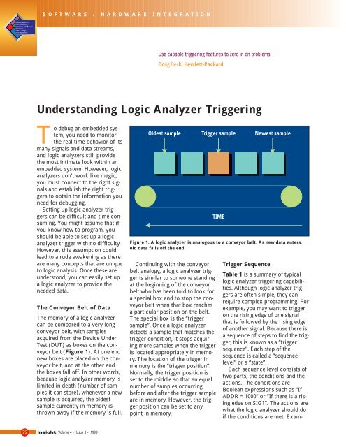
SOFTWARE / HARDWARE INTEGRATIONUse capable triggering features to zero in on problems.Doug Beck, Hewlett-Packard<strong>Understanding</strong> <strong>Logic</strong> <strong>Analyzer</strong> <strong>Triggering</strong>To debug an embedded system,you need to monitorthe real-time behavior of itsmany signals and data streams,and logic analyzers still providethe most intimate look within anembedded system. However, logicanalyzers don’t work like magic;you must connect to the right signalsand establish the right triggersto obtain the information youneed for debugging.Setting up logic analyzer triggerscan be difficult and time consuming.You might assume that ifyou know how to program, youshould be able to set up a logicanalyzer trigger with no difficulty.However, this assumption couldlead to a rude awakening as thereare many concepts that are uniqueto logic analysis. Once these areunderstood, you can easily set upa logic analyzer to provide theneeded data.The Conveyor Belt of DataThe memory of a logic analyzercan be compared to a very longconveyor belt, with samplesacquired from the Device UnderTest (DUT) as boxes on the conveyorbelt (Figure 1). At one endnew boxes are placed on the conveyorbelt, and at the other endthe boxes fall off. In other words,because logic analyzer memory islimited in depth (number of samplesit can store), whenever a newsample is acquired, the oldestsample currently in memory isthrown away if the memory is full.Oldest sampleContinuing with the conveyorbelt analogy, a logic analyzer triggeris similar to someone standingat the beginning of the conveyorbelt who has been told to look fora special box and to stop the conveyorbelt when that box reachesa particular position on the belt.The special box is the “triggersample”. Once a logic analyzerdetects a sample that matches thetrigger condition, it stops acquiringmore samples when the triggeris located appropriately in memory.The location of the trigger inmemory is the “trigger position”.Normally, the trigger position isset to the middle so that an equalnumber of samples occurringbefore and after the trigger sampleare in memory. However, the triggerposition can be set to anypoint in memory.Trigger sampleTIMENewest sampleFigure 1. A logic analyzer is analogous to a conveyor belt. As new data enters,old data falls off the end.Trigger SequenceTable 1 is a summary of typicallogic analyzer triggering capabilities.Although logic analyzer triggersare often simple, they canrequire complex programming. Forexample, you may want to triggeron the rising edge of one signalthat is followed by the rising edgeof another signal. Because there isa sequence of steps to find the trigger,this is known as a “triggersequence”. Each step of thesequence is called a “sequencelevel” or a “state”.Each sequence level consists oftwo parts, the conditions and theactions. The conditions areBoolean expressions such as “IfADDR = 1000” or “If there is a risingedge on SIG1”. The actions arewhat the logic analyzer should doif the conditions are met. Exam-22 Volume 4 • Issue 3 • 1999
ples of actions include triggering thelogic analyzer, going to anothersequence level, or starting a timer.This is similar to an If/Then statementin programming.Each sequence level in the triggersequence is assigned a number. Thefirst sequence level to be executedis always Sequence Level 1, butbecause of Go To actions, the restof the sequence levels can be executedin any order.When a sequence level is executedfor a sample and its conditionsare not met, then the logic analyzeracquires the next sample and executesthe same sequence level. Considerthe following trigger sequence:1. If DATA = 7000 Then TriggerThe logic analyzer will keep acquiringsamples until the data has a valueof 7000, and then it will trigger. Oncea logic analyzer triggers, it will nottrigger again, even if more than onesample meets the trigger condition.If the conditions in a sequencelevel are not met, the logic analyzerwill acquire the next sample andexecute the same sequence levelagain. A trigger condition of“ADDR = 7000” is equivalent to“Keep acquiring more samplesuntil you find one that hasADDR = 7000”. If you set up a triggercondition that is never met, thelogic analyzer will never trigger.If a sample meets the condition,another sample is always acquiredbefore the next sequence level isexecuted. Therefore it is not possiblefor a single sample to be used toTable 1. Summary of <strong>Logic</strong> <strong>Analyzer</strong> <strong>Triggering</strong> Capabilities.meet the conditions of more thanone sequence level, and eachsequence level represents eventsthat occur at different points intime. Two sequence levels can neverbe used to specify two events thathappen simultaneously. For example,consider the following triggersequence:1. If ADDR = 1000 Then Go To 22. If DATA = 2000 Then TriggerIf the following samples wereacquired, the logic analyzer wouldtrigger on sample 7.Sample No. ADDR DATA1 1000 2000This sample meets the condition inSequence Level 12 1010 30003 1020 40004 1030 50005 1040 60006 1050 70007 1060 2000This is where the logic analyzertriggersThe logic analyzer will not triggeron Sample 1 because a new sampleis acquired between the time thatthe condition in Sequence Level 1 ismet and when the condition inSequence Level 2 is tested. A goodway to think of this trigger sequenceis “Find ADDR = 1000 followed byDATA = 2000 and then trigger”.Where to go nextWhen a sequence level’s conditionsare met and there is a “Go To” in theactions, it is clear which sequencelevel will be executed next, but ifthere is no “Go To”, the nextsequence level to be executeddepends upon the logic analyzer’simplementation. On some logic analyzers,if there is no “Go To” thenext sequence level is executed. Onothers, the same sequence level isexecuted again. Because of thisambiguity, it is good practice tospecify a “Go To” action rather thanrelying on the default.Volume 4 • Issue 3 • 199923
SOFTWARE / HARDWARE INTEGRATION CONTINUEDDocument your TriggerSequencesIf a trigger sequence is importantat one time, it is likely to beimportant again, so documentingtrigger sequences is a valuableinvestment in time. Complex triggersequences generally are difficultto understand without someaccompanying explanation, soinline documentation is important,as shown in Figure 3. Inlinedocumentation is included in thetrigger definition itself, allowingyou to describe how differentparts of the trigger work.Setting up logic analyzer triggersis very different than writingsoftware. The job can be greatlysimplified if other work can beleveraged by using pre-definedtrigger functions and previouslywritten triggers that are well documented.Write your own triggersequence only if nothing else isavailable. Finally, when facedwith a difficult trigger to set up,break down the problem intosmaller chunks and deal witheach one separately.TTIntuitive User Interface Improves Your Productivityhe capabilities of modernlogic analyzers must expandalong with the ever-increasingcomplexity of the systems beingcreated. HP’s new VisiTrigger technologyallows you to easily usethese added capabilities even ifyou don’t use your logic analyzerevery day. You can spend moretime making measurements andless time paging through manualsand setting up the logic analyzer.VisiTrigger technology is availablein the HP 16600A/16700Alogic analysis systems. It combinesincreased trigger functionalitywith a user interface that iseasy to understand and use. WithVisiTrigger, capturing complexevents is as simple as point-and-click to choose the trigger functionand fill-in-the-blank to customizeit to your specific task.Three new state-and-timingmodules enhance the VisiTriggertechnology with the addition offour-way branching and globalcounters. The HP 16715A, 16716A,and 16717A state-and-timing modulesoffer up to 333-MHz state andup to 2-GHz timing on each channelall of the time. See page 34 formore information on these newmodules.For additional information onproducts mentioned in this article,check 5 on the reply card, or visithttp://www.hp.com/info/insight3.26 Volume 4 • Issue 3 • 1999