Phased Array Ultrasonic Probe Catalog Phased Array ... - Tecsud
Phased Array Ultrasonic Probe Catalog Phased Array ... - Tecsud
Phased Array Ultrasonic Probe Catalog Phased Array ... - Tecsud

You also want an ePaper? Increase the reach of your titles
YUMPU automatically turns print PDFs into web optimized ePapers that Google loves.
920-117D<br />
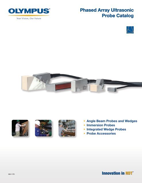
<strong>Phased</strong> <strong>Array</strong> <strong>Ultrasonic</strong><br />
<strong>Probe</strong> <strong>Catalog</strong><br />
• Angle Beam <strong>Probe</strong>s and Wedges<br />
• Immersion <strong>Probe</strong>s<br />
• Integrated Wedge <strong>Probe</strong>s<br />
• <strong>Probe</strong> Accessories
ii<br />
Olympus NDT<br />
Olympus NDT is a leading global manufacturer of innovative<br />
nondestructive testing instruments that are used in a<br />
wide range of industrial and research applications including<br />
aerospace, energy, automotive, electronics, and manufacturing.<br />
Olympus NDT instruments contribute to the quality<br />
of products and add to the safety of infrastructures and<br />
facilities. They include flaw detectors, thickness gages, bond<br />
testers, pulser-receivers, transducers, and advanced systems<br />
for inline applications. Our leading-edge technologies include<br />
ultrasonics, ultrasonic phased array, eddy current, and<br />
eddy current array.<br />
Olympus NDT offers products and services from several<br />
high-quality brands: R/D Tech ® , Panametrics-NDT , NDT<br />
Engineering, Sonic ® , and Nortec ® . For many decades these<br />
brands have earned excellent reputations for providing<br />
cost-effective solutions and excellent support and customer<br />
service.<br />
Based in Waltham, Massachusetts, USA, the company has<br />
sales and service centers in all major industrial locations<br />
worldwide. Visit www.olympusNDT.com for application<br />
support and sales assistance near you.<br />
ISO 9001 Certification<br />
Olympus NDT <strong>Ultrasonic</strong> Transducer Inc. facility’s quality<br />
system is ISO 9001 certified, ensuring an increased level of<br />
quality, a controlled manufacturing process, and continuous<br />
improvement.<br />
understanding<br />
Basic Concepts<br />
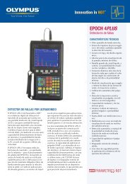
The distinguishing feature of phased array ultrasonic testing is the computer-controlled excitation (amplitude<br />
and delay) of individual elements in a multielement probe. The excitation of multiple piezocomposite elements<br />
can generate a focused ultrasonic beam with the possibility of dynamically modifying beam parameters such as<br />
angle, focal distance, and focal spot size through software. To generate a beam in phase by means of constructive<br />
interference, the various active transducer elements are pulsed at slightly different times. Similarly, the echo from<br />
the desired focal point hits the various transducer elements with a computable time shift. The echoes received by<br />
each element are time-shifted before being summed together. The resulting sum is an A-scan that emphasizes the<br />
response from the desired focal point and attenuates echoes from other points in the test piece.<br />
Examples of focal laws<br />
Delay (ns)<br />
Incident wave front<br />
Active group<br />
16<br />
1<br />
Scanning direction<br />
PA probe<br />
Distance-amplitude curves (DAC) used to create<br />
the time-corrected gain (TCG)<br />
128<br />
45°<br />
Delay (ns)<br />
Angle steering<br />
For manual inspections, real-time readings are essential to quickly position the reflected signal source with<br />
respect to the part geometry and/or probe location.<br />
Top<br />
B0 Bottom<br />
T1 Top<br />
Incident wave front<br />
Illustration of beam focusing Illustration of beam steering<br />
PA probe<br />
�<br />
Acquisition unit<br />
Trigger<br />
Emitting<br />
Receiving<br />
n = 8<br />
Convex<br />
Delay (ns)<br />
PA probe<br />
<strong>Phased</strong> array unit<br />
Transmitting<br />
delays<br />
Receiving delays<br />
and sum<br />
Emission Reception Pulse-echo<br />
t 0<br />
t1<br />
t2<br />
t3<br />
tn<br />
Acquisition time<br />
RA<br />
PA<br />
DA<br />
RA, PA, DA, and SA readings allow the user to accurately<br />
position the defect in real time during an inspection.<br />
RA: Reference point to the indication in gate A<br />
PA: <strong>Probe</strong> front face to the indication in gate A<br />
DA: Depth of the indication in gate A<br />
SA: Sound-path length to the indication in gate A<br />
SA<br />
<strong>Probe</strong> elements<br />
Incident wave front<br />
Pulses<br />
Scanning Patterns<br />
Electronic linear scanning<br />
Sectorial scanning<br />
Dynamic depth focusing<br />
With electronic scanning, a single focal law is multiplexed across With sectorial scanning (also called azimuthal or angular<br />
Dynamic depth focusing (DDF) is a programmable, real-time array<br />
a group of active elements; scanning is performed at a constant scanning), the beam is moved through a sweep range for a response-on-reception accomplished by modifying the delay,<br />
angle and along the phased array probe length (aperture). This specific focal depth, using the same elements; other sweep gain, and excitation of each element as a function of time. DDF<br />
is equivalent to a conventional ultrasonic transducer performing ranges with different focal depths may be added. The angular replaces multiple focal laws for the same focal range created by<br />
a raster scan for corrosion mapping or shear-wave inspection. If sectors may have different values.<br />
the emitted beam with separate “focused beams” at the receiving<br />
an angled wedge is used, the focal laws compensate for different<br />
stage. In other words, DDF dynamically changes the focal distance<br />
time delays inside the wedge.<br />
as the signal returns to the phased array probe. DDF significantly<br />
increases the depth of field and signal-to-noise ratio.<br />
Electronic linear scanning Sectorial scanning<br />
<strong>Phased</strong> <strong>Array</strong> <strong>Probe</strong>s<br />
Linear arrays are the most commonly used phased array probes for industrial applications. Thus, one of<br />
the important features of linear arrays is the active probe aperture.<br />
The active aperture (A) is the total active probe length. Aperture length is given by the following formula:<br />
A = (n –1) •p + e<br />
e<br />
where n = Number of elements in the PA probe<br />
p = Elementary pitch—distance between the centers of<br />
two adjacent elements<br />
Wpassive<br />
e = Element width—width of a single piezocomposite<br />
element (a practical value is e < �/2)<br />
g = Gap between adjacent elements<br />
� =<br />
p<br />
g<br />
A<br />
v<br />
f<br />
where � = Wavelength<br />
v = Material sound velocity<br />
f = Frequency<br />
Time-Corrected Gain<br />
Defect Positioning<br />
70°<br />
60°<br />
45°<br />
70°<br />
60°<br />
45°<br />
70°<br />
60°<br />
45°<br />
In order to cover the whole volume of the part with<br />
consistency, each focal law has to be calibrated for<br />
attenuation and beam spread. This time-correctedgain<br />
(TCG) calibration can be performed with a<br />
calibration block having several identical reflectors<br />
(for example, side-drilled holes) at different depths.<br />
Using a sectorial scan, the probe is moved back<br />
and forth so that each beam hits each reflector. The<br />
amplitude of each signal is recorded (DAC) and<br />
used to construct one TCG curve per focal law.<br />
Linear<br />
Skewing<br />
1.5-D array<br />
Concave<br />
Variable angle<br />
Echo signals<br />
2-D array<br />
Annular<br />
Dual linear<br />
Flaw<br />
Reflected wave front<br />
<strong>Phased</strong> array probes are made in a variety of shapes and sizes for<br />
different applications. A few types are illustrated here:<br />
Flaw<br />
Acquisition without DDF Acquisition with DDF<br />
=<br />
Internal focus<br />
www.olympusNDT.com The leader in phased array technology for more than a decade<br />
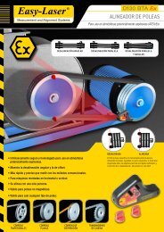
Time delay [ns]<br />
140<br />
120<br />
100<br />
80<br />
60<br />
40<br />
20<br />
0<br />
FD = 15<br />
FD = 30<br />
FD = 60<br />
0 4 8 12 16 20 24 28 32<br />
Element number<br />
70°<br />
60°<br />
45°<br />
FD = 15<br />
FD = 30<br />
FD = 60<br />
Delay values (left) and depth scanning<br />
principles (right) for a 32-element linear<br />
array probe focusing at 15-mm, 30-mm,<br />
and 60-mm longitudinal waves.<br />
70°<br />
60°<br />
45°<br />
45°<br />
Dual 1.5-D<br />
70°<br />
60°<br />
45°<br />
Once the TCG calibration is completed, each focal law has one individual TCG curve. As<br />
a consequence, a reflector will always yield the same signal amplitude, regardless of its<br />
position inside the part and of the beam that detected it. A defect at 3 mm in depth detected<br />
with an angle of 45 degrees will provide the same signal amplitude as if it were at 10 mm and<br />
detected at 60 degrees.<br />
45°<br />
Types of<br />
<strong>Probe</strong>s<br />
Angle Beam<br />
Angle beam probes are used with a<br />
removable or integrated wedge to transmit<br />
a refracted shear or longitudinal wave into<br />
a test piece. They are designed for a wide<br />
range of applications and can be used to<br />
vary the refracted beam angle or the skew<br />
of the beam, depending on the wedge<br />
orientation. The probe face is acoustically<br />
matched to the wedge material.<br />
Integrated Wedge<br />
This variation of an angle beam probe<br />
integrates the wedge into the probe<br />
housing. The wedge configuration is fixed<br />
but offers smaller overall dimensions.<br />
Near Wall<br />
The near wall probe is specifically designed<br />
to minimize the dead zone at probe ends<br />
by reducing the distance between the last<br />
available element and the external edge of<br />
the housing. This probe type is useful for<br />
composite radius and corner inspections,<br />
or any application requiring close contact<br />
to a wall using a 0° wedge.<br />
Immersion<br />
Immersion probes are designed to<br />
be used with a water wedge or in an<br />
immersion tank when the test part is<br />
partially or wholly immersed. The water<br />
acts as a uniform couplant and delay line.<br />
Immersion probes are longitudinal-wave<br />
probes that can be set up for refracted<br />
shear-wave inspection under water.<br />
Immersion probes are mostly intended<br />
for automated inspections.<br />
Contact<br />
Contact probes are especially designed<br />
to be used directly in contact with the<br />
inspected material. They are longitudinalwave<br />
probes with a resistant wear face<br />
acoustically matched to steel.<br />
2-D and 1.5-D <strong>Array</strong>s<br />
Two-dimensional arrays have multiple<br />
strips of linear arrays to allow electronic<br />
focusing and steering in both probe<br />
axes. 2-D arrays have the same number<br />
of elements in both dimensions,<br />
whereas 1.5-D identifies probes with<br />
any combination of uneven numbers of<br />
elements. The probes can be used for<br />
achieving optimal focusing capability or<br />
to cover a defined area without probe<br />
movement.<br />
Dual <strong>Array</strong>s<br />
Two linear or two 1.5-D array probes can<br />
be positioned on a roof-angled wedge<br />
with a transmitting probe. The probe is<br />
paired with a receiving equivalent for<br />
optimal performance in noisy materials<br />
such as austenitic steel. This configuration<br />
is a phased-array equivalent to a dual-<br />
element probe in conventional UT and<br />
is widely used in the power-generation<br />
industry.<br />
Olympus NDT Training Academy<br />
<strong>Phased</strong> array training is available from<br />
professional companies.<br />
Visit www.olympusNDT.com<br />
Copyright © 2006 by Olympus NDT. All Rights Reserved.<br />
Warranty<br />
Olympus NDT Inc. offers a one-year warranty on all phased array<br />
probes sold. These products are guaranteed against all defects in<br />
materials and manufacturing.<br />
All products covered by this warranty must be examined by<br />
Olympus NDT Inc. and receive its approval in advance before any<br />
repairs or replacement are made. Any shipping costs are at the<br />
expense of the customer.<br />
The warranty excludes defects and deterioration due to normal<br />
wear and tear, or caused by an external accident such as:<br />
• Incorrect assembly<br />
• Poor maintenance<br />
• Incorrect usage<br />
• Exposure to temperatures outside the range of –20 °C to 60 °C<br />
for storage, or 10 °C to 40 °C for operation<br />
• Excessive voltage (max. 180 V for 7.5 MHz and below, max.<br />
100 V for 10 MHz and above)<br />
• Use of unqualified couplant<br />
• Unforeseen modifications of the product<br />
Olympus NDT will honor claims for defective products if submitted<br />
within 45 days from the date of shipment, provided that the<br />
product has not been improperly used and is subject to its inspection.<br />
Olympus NDT Inc. will not be held responsible in any way whatsoever<br />
for direct, indirect, special, incidental, or consequential<br />
damages resulting from possession, use, improper installation,<br />
accident, service, modification, or malfunction of the product<br />
(including, without limitation, damages for loss of business profits,<br />
business interruption, loss of business information, or other<br />
pecuniary loss), or from service or modification of the product by<br />
anyone other than Olympus NDT Inc. or an authorized Olympus<br />
NDT service center.<br />
Disclaimer<br />
This document was prepared with particular attention to usage to<br />
ensure the accuracy of the information contained therein. It corresponds<br />
to the version of the products manufactured prior to the<br />
printing date. There may, however, be some differences between<br />
the catalog and the products if the products have been modified<br />
thereafter.<br />
In order to support the growing NDT community, Olympus NDT has published the<br />
“Understanding <strong>Phased</strong> <strong>Array</strong> Technology” poster. This poster has been designed by field<br />
experts to present phased array technology in a concise and clearly illustrated manner.<br />
This poster will become a valuable resource for those who are responding to the large<br />
demand for phased array solutions.<br />
Get your free poster at www.olympusNDT.com.
Table of Contents<br />
Olympus NDT . . . . . . . . . . . . . . . . . . . . . . . . . . . . . . . . . . . . . . . . . . . . . . . . . . . . . . . . . . . . . . . . . . ii<br />
Warranty . . . . . . . . . . . . . . . . . . . . . . . . . . . . . . . . . . . . . . . . . . . . . . . . . . . . . . . . . . . . . . . . . . . . . . ii<br />
Ordering Information . . . . . . . . . . . . . . . . . . . . . . . . . . . . . . . . . . . . . . . . . . . . . . . . . . . . . . . . . . . iv<br />
Testing and Documentation . . . . . . . . . . . . . . . . . . . . . . . . . . . . . . . . . . . . . . . . . . . . . . . . . . . . . . v<br />
Introduction to <strong>Phased</strong> <strong>Array</strong> <strong>Probe</strong>s . . . . . . . . . . . . . . . . . . . . . . . . . . . . . . . . . . . . . . . . . . . . . . . vi<br />
<strong>Phased</strong> <strong>Array</strong> <strong>Probe</strong>s and Wedges<br />
Angle Beam <strong>Probe</strong>s . . . . . . . . . . . . . . . . . . . . . . . . . . . . . . . . . . . . . . . . . . . . . . . . . . . . . . . . . . . . . 7<br />
Small-Footprint and Near-Wall <strong>Probe</strong>s . . . . . . . . . . . . . . . . . . . . . . . . . . . . . . . . . . . . . . . 7<br />
General Purpose . . . . . . . . . . . . . . . . . . . . . . . . . . . . . . . . . . . . . . . . . . . . . . . . . . . . . . . . . . 8<br />
Deep Penetration Applications . . . . . . . . . . . . . . . . . . . . . . . . . . . . . . . . . . . . . . . . . . . . . . 9<br />
Weld Inspection . . . . . . . . . . . . . . . . . . . . . . . . . . . . . . . . . . . . . . . . . . . . . . . . . . . . . . . . . . 10<br />
Wedges for Angle Beam <strong>Probe</strong>s . . . . . . . . . . . . . . . . . . . . . . . . . . . . . . . . . . . . . . . . . . . . . . . . . . 11<br />
Wedge Offset Parameters . . . . . . . . . . . . . . . . . . . . . . . . . . . . . . . . . . . . . . . . . . . . . . . . . 11<br />
Wedge Specifications and Dimensions . . . . . . . . . . . . . . . . . . . . . . . . . . . . . . . . . . . . . . 12<br />
Immersion <strong>Probe</strong>s . . . . . . . . . . . . . . . . . . . . . . . . . . . . . . . . . . . . . . . . . . . . . . . . . . . . . . . . . . . . . 13<br />
Integrated Wedge <strong>Probe</strong>s . . . . . . . . . . . . . . . . . . . . . . . . . . . . . . . . . . . . . . . . . . . . . . . . . . . . . . . 14<br />
<strong>Probe</strong> Accessories<br />
Mini-Wheel Encoder . . . . . . . . . . . . . . . . . . . . . . . . . . . . . . . . . . . . . . . . . . . . . . . . . . . . . . . . . . . 15<br />
Aqualene Elastomer Couplant . . . . . . . . . . . . . . . . . . . . . . . . . . . . . . . . . . . . . . . . . . . . . . . . . . . . 15<br />
Adapters and Extension Cables . . . . . . . . . . . . . . . . . . . . . . . . . . . . . . . . . . . . . . . . . . . . . . . . . . . 16<br />
Technical Information<br />
<strong>Phased</strong> <strong>Array</strong> Technology . . . . . . . . . . . . . . . . . . . . . . . . . . . . . . . . . . . . . . . . . . . . . . . . . . . . . . . . 18<br />
Books and Training . . . . . . . . . . . . . . . . . . . . . . . . . . . . . . . . . . . . . . . . . . . . . . . . . . . . . . . . . . . . . 20<br />
iii
iv<br />
Ordering Information<br />
Numbering System Used to Order Standard <strong>Phased</strong> <strong>Array</strong> <strong>Probe</strong>s<br />
5L16-9.6x10-A1-P-2.5-OM<br />
Frequency<br />
<strong>Array</strong> type<br />
Number of elements<br />
Active aperture<br />
Elevation<br />
Glossary Used to Order <strong>Phased</strong> <strong>Array</strong> <strong>Probe</strong>s<br />
Frequency<br />
1.5 = 1.5 MHz<br />
2.25 = 2.25 MHz<br />
3.5 = 3.5 MHz<br />
5 = 5 MHz<br />
7.5 = 7.5 MHz<br />
10 = 10 MHz<br />
<strong>Array</strong> type<br />
L = linear<br />
EV = curvature in elevation<br />
CC = concave axial curvature<br />
CV = convex axial curvature<br />
A = annular<br />
2D = two-dimensional array<br />
Numbering System Used to Order Wedges<br />
Wedge type<br />
<strong>Probe</strong> mounting<br />
Glossary Used to Order Wedges<br />
Wedge type<br />
SXX = wedge for angle beam probe type XX<br />
Example:<br />
SA2 = wedge for angle beam probe type A2<br />
<strong>Probe</strong> mounting<br />
N = normal<br />
L = lateral (90° skew)<br />
Refracted angle in steel<br />
0 = 0º<br />
45 = 45º<br />
55 = 55°<br />
60 = 60º<br />
How to Order<br />
Active Aperture<br />
Active aperture in mm.<br />
Refer to page vi for details.<br />
Elevation<br />
Elevation in mm.<br />
Example:<br />
10 = 10 mm<br />
Number of elements<br />
Example:<br />
16 = 16 elements<br />
<strong>Probe</strong> type<br />
A = angle beam with external wedge<br />
NW = near-wall<br />
PWZ = weld inspection angle beam<br />
W = angle beam with integrated wedge<br />
I = immersion<br />
Options<br />
Wave type<br />
Refracted angle in steel<br />
Cable length<br />
Cable type<br />
Casing type<br />
<strong>Probe</strong> type<br />
Casing size<br />
Casing size for a given probe type<br />
Cable type<br />
P = PVC outer<br />
M = metal armor outer<br />
Cable length<br />
Cable length in m.<br />
2.5 = 2.5 m<br />
5 = 5 m<br />
10 = 10 m<br />
Connector type<br />
OM = OmniScan ® connector<br />
HY = Hypertronics connector<br />
OL = OmniScan Connector with<br />
conventional UT channel<br />
on element 1 (LEMO ® (00)<br />
connector)<br />
SA1-N60S-IHC-AOD8 Pipe<br />
For pricing or for further information, call your local sales representative.<br />
To quickly locate your local sales representative, go to www.olympusNDT.com.<br />
Wave type<br />
S = shear wave<br />
L = longitudinal wave<br />
IHC (optional)<br />
Irrigation, scanner attachment points, and carbide wear pins<br />
Curvature type<br />
AOD = Axial outside diameter (circumferential scan)<br />
COD = Circumferential outside diameter (axial scan)<br />
Pipe diameter<br />
Measured external pipe diameter in in.<br />
Connector<br />
type<br />
diameter<br />
Curvature type
Testing and Documentation<br />
All Olympus phased array probes are rigorously tested to ensure conformance to the highest standards. An extensive database, containing<br />
characterization records for each probe sold, is maintained by Olympus NDT. This information can be accessed to compare probe properties.<br />
If you have any special testing requirements, please contact Olympus NDT.<br />
<strong>Probe</strong> Test Data Sheet<br />
A <strong>Probe</strong> Test Data Sheet is supplied with the purchase of any probe. This form presents the following information:<br />
Olympus NDT <strong>Ultrasonic</strong> Transducers<br />
60 Decibel Road, Suite 300,<br />
State College, PA 16801<br />
USA<br />
Tel.: (1) (814) 689-1390<br />
Fax: (1) (814) 689-1395<br />
__________________________________________________________________________<br />
PROBE TEST DATA SHEET<br />
Part Number: XAAB-0004<br />
Description: ARRAY, 5-L-64-38.4X10-A2-P-2.5-OM<br />
Serial Number: D0259<br />
<strong>Probe</strong> Information Summary<br />
___________________________________________________________________________<br />
Frequency : 5.0 Mhz Housing : Angle Beam<br />
<strong>Probe</strong> Type : Linear <strong>Array</strong> Cable Jacket : PVC<br />
Element Count : 64 Cable Length : 2.5 m (8.2 ft)<br />
Active Area Dimensions<br />
Length : 38.4 mm (1.51 in)<br />
Elevation : 10.0 mm (0.39 in)<br />
Connector Type : Omniscan<br />
Matching Medium : Rexolite<br />
Pitch : 0.60 mm (0.024 in)<br />
<strong>Probe</strong> Conformance Summary<br />
___________________________________________________________________________<br />
Parameter Measurement Specification Conformance<br />
___________________________________________________________________________<br />
Average Center Frequency (MHz) 5.03 Mhz +/- 10.0% (band) Pass<br />
Average -6dB Bandwidth (%) 81.8 % > 60% (typical) Pass<br />
Overall Vp-p Sensitivity (dB) 1.4 dB < 4.0dB (range) Pass<br />
<strong>Probe</strong> Cable Order Checked and Verified [ ]<br />
<strong>Probe</strong> Uncoupled Response Checked and Verified [ ]<br />
<strong>Probe</strong> Programmable Parameters Checked and Verified [ ]<br />
Tester Signature __________________________ June 19, 2006<br />
________________________________________<br />
Part Number: XAAB-0004<br />
Description: ARRAY, 5-L-64-38.4X10-A2-P-2.5-OM<br />
Serial Number: D0259<br />
0.5<br />
Amplitude (V)<br />
-0.5<br />
0<br />
Magnitude (dB)<br />
-48<br />
Median Waveform (Element 28)<br />
18 Time (us)<br />
19<br />
Median Waveform FFT<br />
0 Frequency (MHz) 10<br />
____________________________________________<br />
AVG MAX MIN RANGE<br />
______________________________<br />
Center Frequency (MHz) 5.03 5.08 4.96<br />
-6dB Bandwidth (%) 81.8 83.4 79.9<br />
Vp-p Sensitivity (dB) -45.9 -45.1 -46.5 1.4<br />
-20dB Pulse Width (ns) 355 360 346<br />
-40dB Pulse Width (ns) 765 880 678 Page 2 of 3<br />
5.6<br />
Freq. (MHz)<br />
4.5<br />
100<br />
Bandwidth (%)<br />
50<br />
3.0<br />
Magnitude (dB)<br />
-3.0<br />
-6dB Center Freq., Avg = 5. MHz<br />
1 Elements<br />
64<br />
-6dB % Bandwidth, Avg = 81.8 %<br />
1 Elements<br />
64<br />
Pk-to-Pk Sensitivity, Avg = -45.9 dB<br />
1 Elements<br />
64<br />
Wedge Specification Sheet<br />
Median Waveform<br />
The median waveform graph displays a median pulse-echo response (typical) from the test target.<br />
Half of the return pulses from the probe elements will have a peak-peak voltage greater than (or<br />
equal to) this median element, and the other half will have a smaller value. Return pulse duration<br />
is shown on the horizontal axis (in microseconds) and amplitude is shown on the vertical<br />
axis (in V). The number of the median element is shown above the graph (in parentheses).<br />
Median Waveform FFT<br />
The median waveform FFT graph shows the calculated spectrum for the median waveform (see<br />
above) over a range of zero MHz to twice the probe’s nominal frequency.<br />
–6dB Center Frequency<br />
The –6dB center frequency bar graph displays a calculated center frequency value for each of<br />
the probe’s elements. This value is calculated by using the halfway point (in frequency) of an<br />
imaginary line intersecting a given element’s spectrum (FFT) data at the –6db level. The average<br />
value of all the probe’s elements is displayed at the top of the graph.<br />
–6dB Percent Bandwidth<br />
The –6dB percent bandwidth bar graph displays a calculated percent bandwidth value for each<br />
of the probe’s elements. This value is determined by using the length (in frequency) of an imaginary<br />
line intersecting a given element’s spectrum (FFT) data at the –6db level and calculated as a<br />
percentage of the center frequency. The average value of all the probe’s elements is displayed at the<br />
top of the graph.<br />
Peak-to-Peak Sensitivity<br />
The peak-to-peak sensitivity bar graph displays a value for each of the probe’s elements, representing<br />
the sensitivity of the probe. This value is calculated by using the magnitude of the<br />
excitation (test) pulse sent to each element and the peak-to-peak voltage measurement of that<br />
element’s pulse-echo return (from the test target). The reported value is –20 multiplied by the log<br />
of the ratio of these two magnitudes. The average value of all the probe’s elements is displayed at<br />
the top of the graph.<br />
Pulse Width<br />
The various pulse-width bar graphs display values representing the axial resolution of the elements’<br />
pulse-echo returns at various levels, such as –20 dB, –30 dB and –40 dB. These values<br />
are calculated by measuring the return pulse’s width (in nanoseconds) at the desired level. Axial<br />
resolution is an important measure of the ability to distinguish individual pulse returns from one<br />
another during normal probe operation. The average value of all the probe’s elements is displayed<br />
at the top of the graph.<br />
A Wedge Specification Sheet is provided with every wedge. This sheet presents the wedge offset parameters of a phased array probe’s first<br />
element for both OmniScan and TomoView software. It is important to note that the values given are only applicable for the wedge and<br />
probe combinations listed.<br />
v
vi<br />
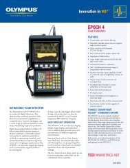
Introduction to <strong>Phased</strong> <strong>Array</strong> <strong>Probe</strong>s<br />
<strong>Phased</strong> array probes are made in a variety of shapes and sizes for different applications. A few types are illustrated here.<br />
Linear<br />
Convex<br />
Skewing<br />
Wpassive<br />
p<br />
e<br />
A<br />
1.5-D array<br />
Concave<br />
Variable angle<br />
g<br />
n = 8<br />
2-D array<br />
Annular<br />
Dual linear<br />
Internal focus<br />
Dual 1.5-D<br />
Typical phased array probes have a frequency ranging from 1 MHz to 17 MHz and have between 10 and 128 elements. Olympus NDT<br />
offers a wide variety of probes using piezocomposite technology, for all types of inspection. This catalog shows standard R/D Tech ®<br />
phased array probes, which are divided into three types: angle beam probes, integrated wedge probes, and immersion probes.<br />
Other types of probes can be designed to suit your application needs.<br />
Linear arrays are the most commonly used phased array probes for industrial applications. An important aspect of phased array probe<br />
design is the active probe aperture.<br />
The active aperture (A) is the total active probe length.<br />
Aperture length is given by the following formula:<br />
A = n • p<br />
where n = number of elements in the PA probe<br />
p = elementary pitch—distance between<br />
the centers of two adjacent elements<br />
A more precise way of calculating aperture is given by this<br />
formula:<br />
A = (n – 1) • p + e<br />
where e = element width—width of a single<br />
piezocomposite element (a practical<br />
value is e < λ/2)<br />
The near-field value gives the maximum depth of usable<br />
focus for a given array. This value is given by the following<br />
formula:<br />
N = D2 f<br />
4c<br />
where D = element diameter<br />
f = frequency<br />
c = material velocity<br />
• To calculate the near-field value in the active (primary)<br />
axis of a phased array probe, D = n’ • p, where n’ = number<br />
of elements per group in the focal law.<br />
• To calculate the near-field value in the passive (secondary)<br />
axis of a phased array probe, D = Wpassive, which is<br />
often called elevation.<br />
For further technical details on phased array technology, see<br />
page 18.
Angle Beam <strong>Probe</strong>s<br />
Small-Footprint and Near-Wall <strong>Probe</strong>s<br />
10L16-A00 10L16-A00 with SA00-N60S wedge<br />
Advantages of Small-Footprint <strong>Probe</strong>s<br />
<strong>Probe</strong> Specifications and Dimensions<br />
Part number<br />
Frequency<br />
(MHz)<br />
Small-footprint probes<br />
Number of<br />
elements<br />
Pitch<br />
(mm)<br />
Note: Dimensions listed herein are approximate and are not to be used for design purposes.<br />
Active<br />
aperture (mm)<br />
H<br />
W<br />
L<br />
A00 casing<br />
Dimensions are without the<br />
strain relief.<br />
H<br />
W<br />
Elevation<br />
(mm)<br />
NW1 casing<br />
L<br />
H<br />
W<br />
A0 casing<br />
External dimensions<br />
mm (in.)<br />
L W H<br />
10L16-A00 10.0 16 0.31 5.0 5.0 8 (0.31) 8 (0.31) 23 (0.90)<br />
5L10-A0-SIDE 5.0 10 0.60 6.0 6.0 13 (0.50) 10 (0.40) 23 (0.90)<br />
5L10-A0-TOP 5.0 10 0.60 6.0 6.0 13 (0.50) 10 (0.40) 23 (0.90)<br />
10L10-A0-SIDE 10.0 10 0.60 6.0 6.0 13 (0.50) 10 (0.40) 23 (0.90)<br />
10L10-A0-TOP 10.0 10 0.60 6.0 6.0 13 (0.50) 10 (0.40) 23 (0.90)<br />
Near-wall probes<br />
5L10-A0-TOP<br />
• Access to confined areas (A00 probe has an 8 × 8 mm footprint)<br />
• Cable connector can come out from either the side or the top<br />
(A0 only).<br />
• Special-design small-footprint wedge<br />
• 10L16-A00 is used for aerospace scribe mark applications.<br />
Advantages of Near-Wall <strong>Probe</strong>s and Wedges<br />
• Shortened dead zone at both ends (1.5 mm between center of first<br />
or last element and housing edge)<br />
• Well suited for composite channel inspection<br />
• Used for C-scan inspection of composites (delamination,<br />
disbonding, and porosity)<br />
5L64-NWI1<br />
3.5L64-NW1 3.5 64 1.0 64.0 7.0 66 (2.60) 19 (0.75) 25 (0.98)<br />
5L64-NW1 5.0 64 1.0 64.0 7.0 66 (2.60) 19 (0.75) 25 (0.98)<br />
These probes come standard with an OmniScan ® Connector and a 2.5 m (8.2 ft) cable or can be specially fitted with other connectors and cable lengths.<br />
L
Angle Beam <strong>Probe</strong>s<br />
General Purpose<br />
Angle beam probes are used with a wedge to transmit a refracted shear or longitudinal wave into a test piece. Designed for a wide range<br />
of applications, they can be used to vary the refracted beam angle or the skew of the beam, depending on the probe orientation.<br />
Advantages<br />
• A wide selection of wedges is available to suit any angle beam application.<br />
• <strong>Probe</strong>s are designed to have a low-profile probe/wedge combination for easier access in restricted areas.<br />
• Wave layers with acoustic adaptation to Rexolite ®<br />
• Captive anchoring screws are provided with the probe.<br />
Typical Applications<br />
A1 and A2 probes<br />
5L16-A1 5L64-A2<br />
• Manual or automated inspection of 6.35 mm to 38 mm<br />
(0.25 in. to 1.5 in.) thick welds<br />
• Detection of flaws and sizing<br />
• Inspections of castings, forgings, pipes, tubes, and machined<br />
and structural components for cracks and welding defects<br />
• 10L64-A2 probe is typically used for stress-corrosion cracking<br />
applications<br />
<strong>Probe</strong> Specifications and Dimensions<br />
Part number<br />
Frequency<br />
(MHz)<br />
Number of<br />
elements<br />
Pitch<br />
(mm)<br />
Note: Dimensions listed herein are approximate and are not to be used for design purposes.<br />
Active<br />
aperture<br />
(mm)<br />
H<br />
W<br />
A1 casing<br />
Elevation<br />
(mm)<br />
L<br />
H<br />
W<br />
A2 casing<br />
External dimensions<br />
mm (in.)<br />
L W H<br />
5L16-A1 5.0 16 0.60 9.6 10.0 17 (0.67) 29 (1.16) 25 (0.98)<br />
10L32-A1 10.0 32 0.31 9.9 7.0 17 (0.67) 29 (1.16) 25 (0.98)<br />
5L64-A2 5.0 64 0.60 38.4 10.0 53 (2.09) 29 (1.16) 35 (1.38)<br />
10L64-A2 10.0 64 0.60 38.4 7.0 53 (2.09) 29 (1.16) 35 (1.38)<br />
These probes come standard with an OmniScan ® Connector and a 2.5 m (8.2 ft) cable or can be specially fitted with other connectors and cable lengths.<br />
L
Angle Beam <strong>Probe</strong>s<br />
Deep Penetration Applications<br />
Angle beam probes are used with a wedge to transmit a refracted shear or longitudinal wave into a test piece. With their large apertures,<br />
deep penetration angle beam probes are designed for the inspection of thick, noisy, or highly attenuative material.<br />
Advantages<br />
A3 A4<br />
A5<br />
• A wide selection of wedges is available to suit any angle beam application.<br />
• Wave layers with acoustic adaptation to Rexolite ®<br />
• Captive anchoring screws are provided with the probe.<br />
Typical Applications<br />
A3, A4, and A5 probes<br />
Deep penetration applications<br />
• Thick plates and welds<br />
• Forgings<br />
• Noisy or granular material<br />
<strong>Probe</strong> Specifications and Dimensions<br />
Part number<br />
Frequency<br />
(MHz)<br />
Number of<br />
elements<br />
Note: Dimensions listed herein are approximate and are not to be used for design purposes.<br />
H<br />
W<br />
L<br />
H<br />
W<br />
A3 casing A4 casing A5 casing<br />
Pitch<br />
(mm)<br />
Active<br />
aperture (mm)<br />
Elevation<br />
(mm)<br />
L<br />
H<br />
W<br />
External dimensions<br />
mm (in.)<br />
L W H<br />
3.5L16-A3 3.5 16 1.60 25.6 16.0 36 (1.41) 36 (1.41) 25 (0.98)<br />
5L16-A3 5.0 16 1.20 19.2 12.0 36 (1.41) 36 (1.41) 25 (0.98)<br />
1.5L16-A4 1.5 16 2.80 44.8 26.0 57 (2.25) 46 (1.80) 30 (1.19)<br />
2.25L16-A4 2.25 16 2.00 32.0 20.0 57 (2.25) 46 (1.80) 30 (1.19)<br />
2.25L32-A5 2.25 32 0.75 24.0 24.0 29 (1.15) 43 (1.67) 24 (0.96)<br />
5L32-A5 5.0 32 0.60 19.2 20.0 29 (1.15) 43 (1.67) 24 (0.96)<br />
These probes come standard with an OmniScan ® Connector and a 2.5 m (8.2 ft) cable or can be specially fitted with other connectors and cable lengths.<br />
L
10<br />
Angle Beam <strong>Probe</strong>s<br />
Weld Inspection<br />
Advantages<br />
<strong>Probe</strong> Specifications and Dimensions<br />
Part number<br />
Frequency<br />
(MHz)<br />
.5L60-PWZ1<br />
• Low-profile housing<br />
• Front-exit cable to avoid interference with scanner probe holder<br />
• Fits special PipeWIZARD ® wedges designed for automated inspection<br />
of girth welds (sophisticated irrigation channels, locking carbide<br />
wear pins).<br />
• Can be ordered with CE-certified Hypertronics connector<br />
• Suitable for manual and automated inspection<br />
Typical Applications<br />
• Automated inspection of girth welds with PipeWIZARD systems<br />
• Manual or automated inspection of thick welds<br />
• Detection of flaws and sizing<br />
• Inspection of castings, forgings, pipes, tubes, and machined and<br />
structural components for cracks and welding defects<br />
Number of<br />
elements<br />
Pitch<br />
(mm)<br />
Note: Dimensions listed herein are approximate and are not to be used for design purposes.<br />
Active<br />
aperture (mm)<br />
SPWZ1-N55S-IHC<br />
Elevation<br />
(mm)<br />
External dimensions<br />
mm (in.)<br />
L W H<br />
5L60-PWZ1 5.0 60 1.0 60.0 10 68 (2.68) 26 (1.02) 30 (1.18)<br />
7.5L60-PWZ1 7.5 60 1.0 60.0 10 68 (2.68) 26 (1.02) 30 (1.18)<br />
5L48-PWZ2 5.0 48 1.0 48.0 10 56 (2.20) 26 (1.02) 30 (1.18)<br />
5L32-PWZ3 5.0 32 1.0 32.0 10 40 (1.58) 26 (1.02) 30 (1.18)<br />
7.5L32-PWZ3 7.5 32 1.0 32.0 10 40 (1.58) 26 (1.02) 30 (1.18)<br />
10L32-PWZ3 10.0 32 1.0 32.0 10 40 (1.58) 26 (1.02) 30 (1.18)<br />
These probes come standard with an OmniScan ® Connector and a 2.5 m (8.2 ft) cable or can be specially fitted with other connectors and cable lengths.<br />
When ordered as part of PipeWIZARD systems, these probes require CE Hypertronics connectors and a 0.6 m (2 ft) cable.<br />
H<br />
W<br />
PWZ1 casing<br />
L
Wedges for Angle Beam <strong>Probe</strong>s<br />
SA00-N60S<br />
Advantages<br />
• Available in standard refracted angles of 0°, 45°, 55°, and 60°<br />
in steel for angle beam inspection from 30° to 70°, SW or LW<br />
• Stainless steel screw receptacles provide a firm anchoring of<br />
probes to wedges.<br />
• Lateral electronic scanning replaces the hand skewing movement<br />
(with lateral wedges).<br />
• The IHC wedge option can be ordered to improve the quality<br />
of the inspection: irrigation, mounting holes for the wedge<br />
holder to work with any R/D Tech ® scanner, and carbide pins to<br />
increase wear resistance.<br />
• Wedges are designed to perform manual or automated scans.<br />
• Custom wedges with specific refracted angles can be ordered;<br />
wedge shape and contour can also be customized.<br />
Angle<br />
SA1-N45L<br />
Wedge Offset Parameters<br />
X Primary offset<br />
Center of<br />
first element<br />
X X T Y<br />
Wedge parameters with OmniScan ®<br />
Y Secondary offset (0 when probe is centered)<br />
Z Height<br />
X T<br />
Wedge parameters with TomoView <br />
Primary axis offset of the middle of the first element<br />
(mm)<br />
Y Secondary axis offset of the middle of the first element<br />
(mm) (measured from the side of the wedge)<br />
Z Height at the middle of the first element (mm)<br />
Note: Dimensions listed herein are approximate and are not to be used for design purposes.<br />
Z<br />
SA2-N55S SA2-0L<br />
Wedge Options<br />
H<br />
W*<br />
W L<br />
L<br />
Basic:<br />
Designed for manual inspection using<br />
gel couplant or water (not fed from an<br />
irrigation system).<br />
IHC (irrigation, holes, and carbides):<br />
Same as Basic but with irrigation, scanner<br />
yoke attachment points, and four<br />
adjustable carbide wear pins.<br />
L W<br />
To Find the Wedge Parameters<br />
• Find the appropriate wedge in either the OmniScan or<br />
TomoView Wedge Database. Parameters are automatically<br />
set once the wedge model is chosen.<br />
• If the wedge is not already in the database, you may download<br />
the latest database update from the Service & Support<br />
section of www .olympusNDT .com.<br />
• Enter the parameters manually using the values provided<br />
on the Wedge Specification Sheet accompanying the<br />
wedge.<br />
For further assistance, call your local sales representative.<br />
H<br />
H<br />
11
Wedge Specifications and Dimensions<br />
Part number <strong>Probe</strong> type<br />
Nominal refracted<br />
beam angle (in steel)<br />
Sweep (°)<br />
<strong>Probe</strong><br />
orientation<br />
Wedge dimensions (mm)<br />
L W W* H<br />
SA00-0L A00 0° LW N/A Normal 16.0 12.0 N/A 12.0<br />
SA00-N45S A00 45° SW 30 to 60 Normal 21.1 12.0 N/A 13.3<br />
SA00-N60S A00 60° SW 45 to 70 Normal 21.3 14.0 N/A 13.3<br />
SA0-0L A0 0° LW N/A Normal 22.7 12.4 N/A 10.8<br />
SA0-N45S A0 45° SW 30 to 60 Normal 32.2 11.3 N/A 20.2<br />
SA0-N45L A0 45° LW 30 to 60 Normal 27.8 11.3 N/A 25.3<br />
SA0-N60S A0 60° SW 45 to 70 Normal 32.4 11.3 N/A 21.5<br />
SA1-0L A1 0° LW N/A Normal 29.0 30.0 N/A 20.0<br />
SA1-N45L A1 45° LW 30 to 60 Normal 28.1 30.0 40.0 24.0<br />
SA1-L45S A1 45° SW -30 to 30 Lateral 45.3 34.9 45.0 26.8<br />
SA1-L45L A1 45° LW -30 to 30 Lateral 44.8 34.9 45.0 42.2<br />
SA2-0L A2 0° LW N/A Normal 65.0 30.0 40.0 20.0<br />
SA2-N45L A2 45° LW 30 to 60 Normal 65.9 30.0 40.0 34.0<br />
SA2-N55S dual A2 55° SW 30 to 70 Normal 68.5 30.0 40.0 43.0<br />
SA2-N60L dual A2 60° LW 45 to 70 Normal 78.1 35.0 40.0 48.5<br />
SA3-0L A3 0° LW N/A Normal 37.7 36.6 50.0 20.0<br />
SA3-N45S A3 45° SW 30 to 60 Normal 55.5 36.6 50.0 30.1<br />
SA3-N45L A3 45° LW 30 to 60 Normal 55.0 36.6 50.0 48.9<br />
SA3-N60S A3 60° SW 45 to 70 Normal 58.5 36.6 50.0 31.6<br />
SA3-N60L A3 60° LW 45 to 70 Normal 52.7 36.6 50.0 39.8<br />
SA4-0L A4 0° LW N/A Normal 59.3 46.6 55.0 20.0<br />
SA4-N45S A4 45° SW 30 to 60 Normal 89.8 46.6 55.0 51.0<br />
SA4-N45L A4 45° LW 30 to 60 Normal 88.5 46.6 55.0 84.6<br />
SA4-N60S A4 60° SW 45 to 70 Normal 86.3 46.6 55.0 45.2<br />
SA4-N60L A4 60° LW 45 to 70 Normal 83.3 46.6 55.0 68.1<br />
SA5-0L A5 0° LW N/A Normal 38.0 45.0 55.0 20.0<br />
SA5-N45S A5 45° SW 30 to 60 Normal 55.6 46.6 55.0 36.6<br />
SA5-N60S A5 60° SW 45 to 70 Normal 45.6 43.5 55.5 25.2<br />
SA5-N60L A5 60° LW 45 to 70 Normal 39.5 50.0 55.0 41.4<br />
SNW1-0L NW1 0° LW N/A Normal 66.0 34.9 40.0 24.9<br />
SPWZ1-0L PWZ1 0° LW N/A Normal 75.0 30.0 40.0 20.0<br />
SPWZ1-N55S REV-C PWZ1 55° SW 30 to 70 Normal 85.8 30.0 40.0 45.5<br />
SPWZ3-0L PWZ3 0° LW N/A Normal 40.0 30.0 40.0 20.0<br />
SPWZ3-N55S PWZ3 55° SW 30 - 70 Normal 65.3 30.0 40.0 38.1<br />
SPWZ3-N60L PWZ3 60° LW 45 - 70 Normal 63.6 30.0 40.0 35.3<br />
* Width with the IHC wedge option
Immersion <strong>Probe</strong>s<br />
Immersion probes are designed to be used with a water wedge or in an immersion tank when the test part is partially or wholly immersed.<br />
They are longitudinal wave probes that can be set up for refracted shear-wave inspection using a Rexolite ® wedge.<br />
Advantages<br />
10L12 -I2<br />
• Acoustic impedance matching to water<br />
• Design allows fitting on water wedges for easier coupling on many<br />
surfaces and an adjustable water path (when the part to inspect<br />
cannot be immersed in a tank).<br />
• Linear scanning allows coverage of 30 mm to 90 mm in one line,<br />
with very high accuracy.<br />
• Corrosion-resistant stainless steel case<br />
• Waterproof guaranteed up to 1 m (3.28 ft) underwater<br />
Typical Applications<br />
• Inspection of thin plate or tubing (steel, aluminum, or other)<br />
• Composite inspection for delamination, disbonding, etc.<br />
• Inline thickness gaging<br />
• Automated scanning<br />
<strong>Probe</strong> Specifications and Dimensions<br />
Part number<br />
Frequency<br />
(MHz)<br />
Number of<br />
elements<br />
Pitch<br />
(mm)<br />
Note: Dimensions listed herein are approximate and are not to be used for design purposes.<br />
Active<br />
aperture (mm)<br />
W<br />
I3 casing<br />
Elevation<br />
(mm)<br />
L<br />
External dimensions<br />
mm (in.)<br />
L W H<br />
5L64-I1 5.0 64 0.60 38.4 10.0 50 (1.97) 19 (0.75) 25 (0.98)<br />
10L64-I1 10.0 64 0.50 32.0 10.0 50 (1.97) 19 (0.75) 25 (0.98)<br />
5L128-I2 5.0 128 0.60 76.8 10.0 83 (3.27) 21 (0.83) 35 (1.38)<br />
10L128-I2 10.0 128 0.50 64.0 7.0 83 (3.27) 21 (0.83) 35 (1.38)<br />
2.25L128-I3 2.25 128 0.75 96.0 12.0 102 (4.02) 21 (0.83) 35 (1.38)<br />
5L128-I3 5.0 128 0.75 96.0 10.0 102 (4.02) 21 (0.83) 35 (1.38)<br />
These probes come standard with an OmniScan ® Connector and a 2.5 m (8.2 ft) cable or can be specially fitted with other connectors and cable lengths.<br />
H<br />
13
14<br />
Integrated Wedge <strong>Probe</strong>s<br />
Advantages<br />
5L16-45SW1<br />
• <strong>Probe</strong> and wedge in the same housing<br />
• The lowest-profile probe-and-wedge combination for contact angle<br />
beam inspection.<br />
• Coupling always good between probe and wedge interfaces, no<br />
need for couplant between the probe and wedge<br />
• Very small assembly for easy access in restricted areas<br />
• Inspections of 30° to 70° in steel, SW or LW<br />
• Easy to handle<br />
• <strong>Probe</strong>s with an internal wedge can be specially ordered to fit a specific<br />
curvature radius.<br />
Typical Applications<br />
• Manual weld inspection of 6.35 mm to 19 mm (0.25 in. to 0.75 in.)<br />
thick surfaces (butt joints, corner joints, tee joints), using 40° to 70°<br />
simultaneously<br />
• Manual inspection of stress corrosion cracking<br />
<strong>Probe</strong> Specifications and Dimensions<br />
Part number<br />
Frequency<br />
(MHz)<br />
Number of<br />
elements<br />
Pitch<br />
(mm)<br />
Active<br />
aperture (mm)<br />
Note: Dimensions listed herein are approximate and are not to be used for design purposes.<br />
Elevation<br />
(mm)<br />
H<br />
W<br />
W1 casing<br />
Nominal<br />
refracted beam<br />
angle in steel<br />
L<br />
External dimensions<br />
mm (in.)<br />
L W H<br />
2.25L16-45SW1 2.25 16 0.75 12.0 12 45° SW 30 (1.18) 15 (0.59) 31 (1.22)<br />
2.25L16-45LW1 2.25 16 0.75 12.0 12 45° LW 30 (1.18) 15 (0.59) 31 (1.22)<br />
5L16-45SW1 5.0 16 0.60 9.6 10 45° SW 30 (1.18) 15 (0.59) 31 (1.22)<br />
5L16-45LW1 5.0 16 0.60 9.6 10 45° LW 30 (1.18) 15 (0.59) 31 (1.22)<br />
These probes come standard with an OmniScan ® Connector and a 2.5 m (8.2 ft) cable or can be specially fitted with other connectors and cable lengths.
Mini-Wheel Encoder<br />
The Mini-Wheel Encoder is used for the positioning and dimensioning of defects on the scan axis. It can synchronize data acquisition<br />
with probe movement. The Mini-Wheel Encoder is waterproof and compatible with the HST-X04 scanner as well as Olympus NDT<br />
standard phased array wedges, which can be connected with the included bracket kit. This miniature encoder is built with an aluminium<br />
casing and a stainless steel wheel.<br />
• Waterproof<br />
• Small dimensions<br />
• Encoder resolution is engraved on the wheel<br />
• Removable encoder wheel<br />
• Double O-ring tire for better adherence<br />
• Metallic strain relief for cable protection<br />
• Spring-loaded pin for encoder attachment<br />
• Two M3 threaded holes on the top of the casing for a rigid<br />
attachment<br />
• DE version is compatible with the OmniScan instrument<br />
• BX version is compatible with the FOCUS LT instrument<br />
Aqualene Elastomer Couplant<br />
Aqualene is an elastomer designed specifically for ultrasonic<br />
inspection applications. The acoustic impedance of the material<br />
is nearly the same as water and its attenuation coefficient is lower<br />
than many documented elastomers and plastics.<br />
Applications for nondestructive testing include:<br />
• Flexible couplant pads with minimal water addition<br />
• Low-velocity delay lines<br />
• Water box membrane<br />
Aqualene elastomer couplant reduces the drawbacks of wet coupling<br />
when used on porous or refractory surfaces. It allows a minimal<br />
amount of couplant to be used while protecting the probe<br />
when in direct contact with the part. Furthermore, Aqualene may<br />
serve as a thermic insulator.<br />
Aqualene couplant products are available in many sizes and<br />
thicknesses, and custom designs are also available.<br />
RESOLUTION<br />
12 steps/mm<br />
A<br />
A = 27 mm (1.06 in.) D = 24 mm (0.94 in.)<br />
B = 28.7 mm (1.12 in.) E = 17.5 mm (0.69 in.)<br />
C = 22.5 mm (0.89 in.) F = 6 mm (0.23 in.)<br />
Mini-Wheel Encoder Specifications<br />
Part number<br />
Cable length<br />
(m)<br />
One of the many<br />
uses of Aqualene:<br />
phased array<br />
probe cluster used<br />
in an R/D Tech ®<br />
industrial pipe<br />
inspection system.<br />
B<br />
C<br />
E<br />
Connector Instrument<br />
ENC1-2.5-DE 2.5 DE-15 OmniScan<br />
ENC1-5-DE 5.0 DE-15 OmniScan<br />
ENC1-2.5-BX 2.5 Bendix TomoScan FOCUS LT<br />
ENC1-5-BX 5.0 Bendix TomoScan FOCUS LT<br />
F<br />
D<br />
15
16<br />
Adapters and Extension Cables<br />
Adapters<br />
Part number Description<br />
OMNI-A-ADP03 Adapter to connect a Hypertronics PA probe to the OmniScan ®<br />
OMNI-A-ADP04<br />
OMNI-A-ADP05<br />
OMNI-A-ADP11<br />
OMNI-A-ADP12<br />
Extension cables<br />
E128P5-0000-OM<br />
E128P10-0000-OM<br />
E128P5-0004-OM<br />
E128P5-0202-OM<br />
E128P10-0004-OM<br />
E128P10-0202-OM<br />
Combining extension cables with adaptors offers numerous connection possibilities.<br />
Adapter to connect any PA probe that has an OmniScan Connector to the<br />
Tomoscan FOCUS or Tomoscan III PA, or to other PA equipment having<br />
a Hypertronics input<br />
Y-adapter that has an OmniScan Connector to support two PA probes.<br />
Connector layout: 1 female output and 2 male inputs.<br />
Adapter to connect up to 8 UT probes having LEMO ® (00) connectors to<br />
the OmniScan Connector of an OmniScan PA or of a TomoScan FOCUS<br />
LT.<br />
Enables the use of conventional UT probes with a PA instrument.<br />
Adapter to connect up to 16 UT probes having LEMO (00) connectors<br />
to an OmniScan PA or to a TomoScan FOCUS LT. Supplied with a 1 m<br />
cable.<br />
Enables the use of conventional UT probes with a PA instrument.<br />
Extension cable with an OmniScan Connector at both ends. 128 elements<br />
are available for phased array use.<br />
Extension cable with an OmniScan Connector at both ends. Four conventional<br />
UT channels with LEMO ® connectors are provided; 124 elements are<br />
available for phased array use.
Numbering System Used to Order PA Extension Cables<br />
Number of elements<br />
Cable type<br />
Cable length<br />
Number of elements in extension<br />
E128 = 128 elements<br />
Cable type<br />
P = PVC outer<br />
M = metal armor outer<br />
Cable length<br />
0 = 0.5 m<br />
5 = 5 m<br />
10 = 10 m<br />
<strong>Probe</strong> Options<br />
OmniScan Connector<br />
E128P10-0004-OM<br />
Connector on the probe side<br />
0000 = OmniScan Connector with 0 LEMO<br />
0004 = OmniScan Connector with 4 LEMO at pins 125 to 128<br />
0202 = OmniScan Connector with 4 LEMO at pins 63–64 and 127–128<br />
HY = Hypertronics <br />
Connector on the instrument side<br />
OM = OmniScan Connector<br />
HY = Hypertronics connector<br />
OL OmniScan Connector<br />
• Additional conventional UT channel (LEMO 00 connector) directly on the<br />
OmniScan Connector of the phased array probe<br />
• Allows simultaneous or alternate use of phased array and pulse-echo using a<br />
single setup.<br />
• To order this option replace OM with OL in the Connector type code of the<br />
probe part number (see page iv).<br />
Metal Armor Outer<br />
Instrument Connector<br />
<strong>Probe</strong> Connectors<br />
• Offers mechanical protection against cut, wear, and harsh environments<br />
• Available for most standard probes and extension cables<br />
• Enables probe recognition. The main probe characteristics are sent to the<br />
OmniScan ®<br />
phased array instrument for faster and error-free setups.<br />
• No more pins to bend or break<br />
• Splash-proof casing<br />
• Improved shielding<br />
• Compact design<br />
• Improved signal-to-noise ratio<br />
1
1<br />
<strong>Phased</strong> <strong>Array</strong> Technology<br />
The distinguishing feature of phased array ultrasonic testing is the computer-controlled excitation (amplitude and delay) of the individual<br />
elements in a multielement probe. The excitation of these multiple piezocomposite elements generates a focused ultrasonic beam, allowing<br />
the dynamic modification of beam parameters such as angle, focal distance, and focal spot size through software. To generate a<br />
beam in phase by means of constructive interference, the various active elements are pulsed at slightly different times. Similarly, the echo<br />
from the desired focal point hits the various elements with a computable time shift. The echoes received by each element are time-shifted<br />
before being summed together.<br />
The resulting sum is an A-scan that emphasizes the response from the desired focal point and attenuates echoes from other points in the<br />
test piece.<br />
All R/D Tech® phased array systems offer the following capabilities:<br />
Software Control of Beam Angle, Focal Distance, and<br />
Focal Spot Size<br />
By precisely controlling the delays between the probe elements,<br />
beams of various angles, focal distances, and focal spot sizes can<br />
be produced. The echo from the desired focal point hits the various<br />
probe elements with a computable time shift.<br />
The signals received at each probe element are time-shifted before<br />
being summed together. The resulting sum is an A-scan emphasizing<br />
the response from the desired focal point and attenuating<br />
various other echoes from other points in the material.<br />
Acquisition unit<br />
Emitting<br />
Receiving<br />
Trigger<br />
<strong>Phased</strong> array unit<br />
Transmitting<br />
delays<br />
Receiving delays<br />
and sum<br />
<strong>Probe</strong> elements<br />
Pulses<br />
Echo signals<br />
Incident wave front<br />
Flaw<br />
Reflected wave front<br />
Flaw<br />
Multiple-Angle Inspection with a Single, Small,<br />
Electronically Controlled, Multielement <strong>Probe</strong><br />
A conventional UT inspection requires a number of different<br />
transducers. A single phased array probe can be made to sequentially<br />
produce the various angles and focal points required by the<br />
application.<br />
Delay (ns)<br />
�<br />
Angle steering<br />
Incident wave front<br />
Inspection of Complex Shapes<br />
PA probe<br />
The capacity to produce at will, and under computer control, various<br />
beam angles and focal lengths is used to inspect parts with<br />
complex shapes such as turbine discs, turbine blade roots, reactor<br />
nozzles, and other complex shapes.
High-Speed Scans with No Moving Parts<br />
While phased arrays imply handling the many signals from<br />
multielement probes, it is important to note that the resulting signal<br />
is a standard RF signal (or A-scan) comparable to that of any<br />
conventional system with a fixed-angle transducer.<br />
This signal may be evaluated, processed, filtered, and imaged as<br />
any A-scan from a conventional UT system. B-scans, C-scans, and<br />
D-scans built from the A-scan are also identical to that of a conventional<br />
system. The difference is that a multiple-angle inspection<br />
can be handled with a single probe.<br />
Multiplexing also allows motionless scanning: a focused beam is<br />
created using a number of the total elements in a long phased-array<br />
probe. The beam is then shifted (or multiplexed) to the other<br />
elements to perform a high-speed scan of the part with no probe<br />
movement along that axis. More than one scan may be performed<br />
with various inspection angles.<br />
The principle can be applied to flat parts using a linear phased<br />
array probe or to tubes and rods using a circular phased array<br />
probe.<br />
1<br />
Active group<br />
16<br />
Scanning direction<br />
High-speed linear scan: R/D Tech ®<br />
phased array systems can also be used to inspect flat<br />
surfaces such as steel plates. Compared to a wide, single-element transducer—often referred to<br />
as a “paint brush”—phased array technology offers a much higher sensitivity due to the use of a<br />
small focused beam.<br />
128<br />
Defect Positioning<br />
For manual inspections, real-time readings are essential to quickly<br />
position the reflected signal source with respect to the part geometry<br />
and/or probe location.<br />
RA, PA, DA, and SA readings allow the user to accurately position<br />
the defect in real time during an inspection.<br />
RA: Reference point to the indication in gate A<br />
PA: <strong>Probe</strong> front face to the indication in gate A<br />
DA: Depth of the indication in gate A<br />
SA: Sound-path length to the indication in gate A<br />
SA<br />
45°<br />
RA<br />
PA<br />
DA<br />
B0<br />
T1<br />
Top<br />
Bottom<br />
Top<br />
1
Books and Training<br />
�������� �� ������ �����<br />
���������� ����������<br />
������������<br />
�������� ��������� ��� ������<br />
������������<br />
�� ������ ����� ����������<br />
���������� ������������<br />
Training<br />
�������� ��������� ��� ������<br />
• Davis NDE (USA)<br />
• DGZfP (Germany)<br />
• Eclipse Scientific Products (Canada)<br />
������ �����<br />
��������� ����������<br />
������ ��������� ������� ���<br />
��������<br />
�������� ��������� ��� ������<br />
��������� ���������� �������<br />
��� �������� ����� �����<br />
� ��������<br />
�������� ��������� ��� ������<br />
Olympus NDT has developed its unique Training Academy, which is a partnership with major training companies in an effort to offer<br />
comprehensive courses in phased array technology and applications. Courses range from a two-day “Introduction to <strong>Phased</strong> <strong>Array</strong>” program<br />
to an in-depth, two-week “Level II <strong>Phased</strong> <strong>Array</strong>” course. In both cases, students experience practical training utilizing the portable<br />
OmniScan ® phased array unit. Courses lead either to recognized certification or to certificates of attendance.<br />
Courses are currently being offered at the training facilities of participating companies as well as at customer-determined locations worldwide.<br />
Customized courses can also be arranged. Check the latest course schedule at www.olympusNDT.com.<br />
Olympus NDT Certified Training Partners<br />
www.olympusNDT.com<br />
info@olympusNDT.com<br />
NEW Advances in <strong>Phased</strong> <strong>Array</strong> <strong>Ultrasonic</strong> Technology Applications<br />
Over the last few years, phased array ultrasonics has entered many new markets and industries. It is<br />
now routinely used for pipeline inspection, general weld integrity, in-service crack sizing, and aerospace<br />
fuselage inspection. These recent applications have brought phased array technology to new<br />
and improved levels across the industrial spectrum. Advances in <strong>Phased</strong> <strong>Array</strong> <strong>Ultrasonic</strong> Technology<br />
Applications covers the latest developments in phased array technology as well as its implementation<br />
worldwide.<br />
Olympus NDT<br />
48 Woerd Avenue • Waltham, MA, 02453 • USA<br />
Tel.: (1) 781-419-3900 • Fax: (1) 781-419-3980<br />
12569 Gulf Freeway • Houston, TX, 77034 • USA<br />
Tel.: (1) 281-922-9300 • Fax: (1) 952-487-8877<br />
���� ������<br />
PA_<strong>Probe</strong>_<strong>Catalog</strong>_EN_0705 • Printed in Canada • Copyright © 2004–2007 by Olympus NDT.<br />
All brands are trademarks or registered trademarks of their respective owners.<br />
Also available<br />
Introduction to <strong>Phased</strong> <strong>Array</strong> <strong>Ultrasonic</strong><br />
Technology Applications<br />
Note that this book is also available in Japanese.<br />
<strong>Phased</strong> <strong>Array</strong> Technical Guidelines<br />
Automated <strong>Ultrasonic</strong> Testing for Pipeline<br />
Girth Welds.<br />
• Lavender International (UK)<br />
• TEST NDT (USA)<br />
• Vinçotte Academy (Belgium)<br />
Olympus NDT u.K. lTD.<br />
12 Nightingale Close • Rotherham, South Yorkshire, S60 2AB • UK<br />
Olympus siNgapOre pTe. lTD.<br />
491B River Valley Road 12-01/04, Valley Point Office Tower, 248373 • Singapore<br />
Olympus ausTralia pTy. lTD.<br />
PO Box 985 • Mount Waverley, VIC 3149 • Australia