Max Power (James Nichols, Ryan Haldimann, Miki Stowers ... - helix
Max Power (James Nichols, Ryan Haldimann, Miki Stowers ... - helix
Max Power (James Nichols, Ryan Haldimann, Miki Stowers ... - helix
- No tags were found...

Create successful ePaper yourself
Turn your PDF publications into a flip-book with our unique Google optimized e-Paper software.
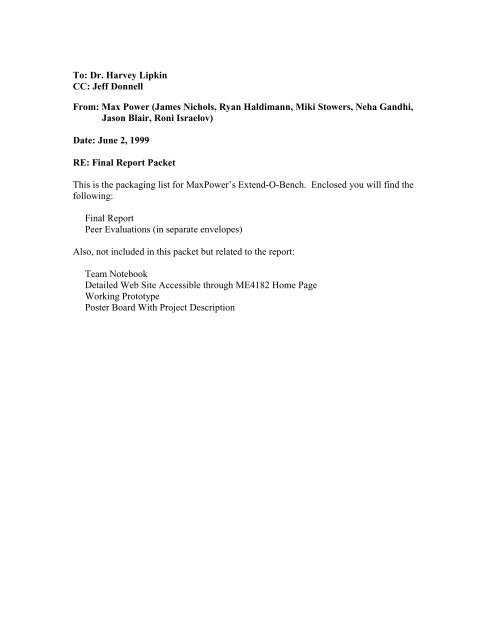
Collapsible Free Weight BenchFinal ReportME 4182June 2, 1999Team <strong>Max</strong><strong>Power</strong><strong>Ryan</strong> <strong>Haldimann</strong>Roni IsraelovJason BlairNeha Gandhi<strong>Miki</strong> <strong>Stowers</strong><strong>James</strong> <strong>Nichols</strong>
Executive SummaryCurrently, there are no collapsible home workout units that incorporate the usageof free weights in the marketplace. Most collapsible home workout systems use eitherelastic bands or flexible fiberglass rods for resistance. This is a significant problem toserious weightlifting enthusiasts. Serious weightlifters want to feel the burn that can onlybe attained by using free weights.<strong>Max</strong><strong>Power</strong> believes that this lack of a ‘real’ workout unit provides an excellentopportunity for an innovative concept in the marketplace. It is important that this unit iscapable of supporting the most common exercises, which include decline, incline, andflat bench. This unit should be completely adjustable so that it can meet the needs ofpeople of all sizes. Finally, this unit should be able to fold into a compact unit that can betransported quickly for easy storage.Important criteria for the design were selected and include weight, cost, collapsedsize, ease of use, and accommodation of selected exercises. Several subsystems forconceptual designs were considered and include structural support, adjustment system,collapsing system, and transportation system. Several design concepts were created andthe best design was chosen using a qualitative selection process. Finally, structuralanalysis was performed on the unit to ensure that it can properly support the necessaryloads.This report discusses the procedures taken during the development of the workoutunit and presents and explains the resulting design. The justification and results of eachprocedure are explained and the final design is described with the aid of part drawingsand diagrams.
Table of ContentsIntroduction . . . . . . . . . . . . . . . . . . . . . . . . . . . . . . . . . . . . . . . . . . . . . . . . . . . . . . . .1Description of Design . . . . . . . . . . . . . . . . . . . . . . . . . . . . . . . . . . . . . . . . . . . . . . . ..1Conclusion . . . . . . . . . . . . . . . . . . . . . . . . . . . . . . . . . . . . . . . . . . . . . . . . . . . . . . . . .6Appendix . . . . . . . . . . . . . . . . . . . . . . . . . . . . . . . . . . . . . . . . . . . . . . . . . . . . . . . . . ..7
IntroductionThe product that <strong>Max</strong><strong>Power</strong> selected to engineer and construct is a collapsiblehome free-weight workout bench. This workout unit will be capable of accommodatingthe most popular bench exercises, which include incline, decline, and flat bench press.The engineering and design of this unit will require creating innovative solutions tonumerous subsystems that are highly interconnected.<strong>Max</strong><strong>Power</strong> believes that a demand exists for a collapsible home free-weight unit.Currently, the only collapsible home units that exist do not combine the featuresmentioned above. Workout units that allow the usage of free weights do notaccommodate multiple exercises, while those that accommodate multiple exercises useelastic bands or flexible fiberglass rods. This product will meet the needs of seriousworkout enthusiasts who want the convenience of a home unit that does not take upexcessive space.The most important criteria for the design to meet is the ability to accommodatemultiple exercises, collapse, support adequate weight, and meet certain size, weight, andcost constraints. Finally, it is important that the product be easy to use. This includes theadjustment of the bench for each exercise, the collapsing of the bench, and thetransportation of the bench. We believe that a product that meets the above goals willbecome a popular home workout unit for the serious weightlifter.Description of DesignFigure 1 shown below is a top view of the final design and Figure 2 on the nextpage displays the side view.1
Figure 1: Top view of Final DesignFigure 2: Side View of Final DesignDetail drawings of each item are available in the Appendix (Figures A2-A12).The support system of the Extend-o-Bench consists of items 2, 6, 7, 8, 11 and 12from Figures 1 and 2. This system provides the main support to the bench and containsthe support arms used to hold the weights. This system had to be specially designed witha series of nested tubing and slots so that it would collapse into a 6’x3’x1’ unit.Item 2 is a 4”x2”x1/8” tubing that acts as the center beam of the base. It supportsthe bench via two hinges and two holes that the bench supports (items 3 and 10) set into.The center beam is connected to items 6 and 7. Item 7 is the support arm expander. Itsend slides in a slot alongside the center beam pushing the support arm housing (item 6)outwards. The expanders keep the support arms a fixed distance apart. The support armhousing is connected to the expander and center beam by hinges. A slot runs along thehousing’s length for the support arms (items 11 and 12) to travel. The support arms andhousing were designed so that they could be nested. When collapsed item 12 rests withinitem 11 and both fit snugly within the housing. During setup, the support arms can bepulled out of the housing and rotated to an upright position. A support arm stabilizer(item 8) is then connected to item 11 by a quick-release pin to maintain this position.Item 11 provides the main weight support while item 12 enables adjustability. Item 12contains a series of holes placed 3 inches apart which allows the height of the supportarms to vary between 3 and 6 feet. When one of these holes is in alignment with the holeat the top of item 11 a pin is inserted to keep the support arm in place. The holes are2
located on the side of the tubing that faces the bench so that the user can easily adjust thesupport arm height while remaining on the bench.It is important that the support system be able to sustain a large weight. The armsneed to be able to support a maximum load of 750 pounds. Failure of the system couldbe disastrous; therefore, analysis was done to ensure that the system was safe. This wasdone for two cases. Case 1 determined whether the system could support weightproduced from gravitational forces alone. Case 2 modeled a person throwing the weightsback onto the support bar.It was determined that failure would most likely occur by shear of the pins ordeformation of the support arms at the pin’s hole. The first pin evaluated was the pinused to adjust the support height. Figure 3 shows the forces on the pin and the equationsthat follow were used to solve for the maximum force that the pin could withstand.Figure 3: Shear of the adjuster pinS y2F= 4πD42F40000 psi = 42 π (0.5")4F =15, 707lbsThe maximum force that the member could resist at this location was determined by thefollowing equations:23
40000 psi =FS y= 4DtF4(0.5")(0.125")F =10, 000lbsThe result was that the support arms could resist a weight of 10,000lbs maximum. Beingthat the goal of the bench was to hold 750lbs, the bench’s design exceeds therequirements.In the second case, the reaction was determined for weights being thrown backonto the support arms. Figure *.* shows the forces applied to the arms.Figure 4: Forces on the support armThe calculations in this case were more complex. The impact time, velocity of theweights and the impact force were all unknowns. The force, F n , that was used was thesmallest force a member could withstand, which occurred at a pin hole in one of thebench’s supports. This was a value of 5880 lbs. The sum of the moments about point 0were taken to yield an impact force of 1247.3 lb f . Estimating 450 pounds of weightmoving at a half meter per second, 1.64 ft/s, the impact time was given by the followingequation:F ∆t= mv∆t=mv2F=450lbm*1.64 ft / s2*1247.3lbf= 0.005sIt is unsure as to what the impact time reveals. If the impact time had been a second, thenthe support arms would have been sure to fail. The fact that the impact time is smallprovides some comfort that the design is sufficient.4
To accommodate the collapsibility of the bench, two special brackets were used.Figure 4 shown below shows the two brackets. These “U” brackets were designed toallow both ends of the bench to move vertically. This allows for the bench to bepositioned in both the inclined and declined position. They also allow for adjustment ofthe seat portion at all time.Figure 4: Drawings of Outer and Inner U-BracketsThe brackets connect to the seat posts to the bench frame. The two beams runningunder the bench are connected to the outermost U bracket and the inner U bracket isconnected to either the seat or back support of the bench. All U brackets are connected onthe bottom to a post that may or may not be nested within another post. The innermost Ubracket is free to move vertically when it is unpinned. This allows the seat to rotate upand it allows the back support to rotate up independently. These adjustments cover theinclined bench position.The outer U bracket at the foot of the bench also moves vertically toaccommodate the declined position. Moving this bracket vertically causes the benchframe, which carries the seat and back support, to move into the decline position. Thusthe seat post closest to the foot of the bench is comprised of three nested sections, and thepost at the head is comprised of two nested sections. These nested sections allow the postto take up minimal room and collapse easily.The U brackets are made of ¼” steel plate welded together for maximum support.The holes cut in the lower portion of each U bracket are large enough to accommodatethe outer tubing for the seat post at the head of the bench and the middle piece of tubingin the seat post at the foot of the bench. The brackets are welded into place at eachlocation for maximum strength.5
ConclusionsThe goal of this project was to create a weight bench that supports incline,decline, and flat bench and collapses down to a portable size. The project was completedwith all of its major goal’s completed. The final bench design collapses down to a sizethat is easily storable underneath a bed or in a closet. By the use of “U-brackets”, thebench is able to accommodate to all the weight lifting positions mandated by the problemstatement.All the parts of the final design are itemized below with cost.Table 1 Steel Tubing CostSize length Cost2 x 2 309” $129.253 x 1 98” $76.761 ¾ x 1 ¾ 64” $26.001 ½ x 1 ½ 91” $56.70¾ x ¾ 96” $16.06Table 2 Steel Pin CostStyle Size CostT-Handle Steel Pin 4”L ½”D $15.36Steel Round 6”L ½”D $7.86Ring Grip Quick Release Pins 1 ½”L 3/8”D $8.80Table 3 Seat CostPartCostPlywood (.75”x24”x48”) $7.25Vinyl $5.00Padding $5.00Table 4 Total CostPartCostTubing $278.77Pins $32.02Backboard/Seat $17.25Miscellaneous $50.00Total Cost $378.04Future WorkThe following problems and tasks have yet to be completed:1) The sliders on the bottom of the bench that attach to the interior U-bracket need to beevaluated for structural integrity.2) The bench support post at the head can be reduced to just one adjusting member.3) An effective leg support for the decline position needs to be investigated.4) When in the extended position the bench extends far beyond the weight support arms.5) When in the collapsed position the bench could be slid towards the head of the benchby extending the slots already cut in the support posts.6
AppendixFigure A1: Extend-o-Bench Assembly (Top and Side View)7
Figure A2: Detail - Bench SeatFigure A3: Detail - Bench Base-Center Beam8
Figure A4: Detail - Bench Seat SupportFigure A5: Detail - Bench Seat Adjuster9
Figure A6: Detail - Bench Decline AdjusterFigure A7: Detail - Support Arm Housing10
Figure A8: Detail - Support Arm ExpanderFigure A9: Detail - Support Arm Stabilizer11
Figure A10: Detail - Bench Incline AdjusterFigure A11: Detail - Bench Incline Support12
Figure A12: Detail - Support Arms13
Figure 13: Solid Model of Extend-o-BenchFigure 14: Solid Model of Extend-o-Bench (Collapsed View)14