1511 Series - Maintenance Manual
1511 Series - Maintenance Manual
1511 Series - Maintenance Manual
- No tags were found...

Create successful ePaper yourself
Turn your PDF publications into a flip-book with our unique Google optimized e-Paper software.
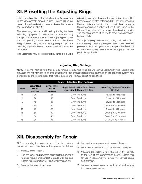
XI. Presetting the Adjusting RingsIf the correct position of the adjusting rings (as measuredin the disassembly procedure (see Section XII) is notknown, the valve adjusting rings may be positioned usingthe information in Table 1.The lower ring may be positioned by turning the loweradjusting ring up until it contacts the disc. After choosingthe appropriate orifice size, turn the adjusting ring downthe corresponding number of notches listed in the “LowerRing” column. Then, replace the adjusting ring pin. Theadjusting ring must be free to move both directions, butnot rotate.The upper ring may be positioned by turning the upperadjusting ring down towards the nozzle bushing, until itbecomes level with the bottom of disk. Then after choosingthe appropriate orifice size, turn the adjusting ring downthe corresponding number of turns (360°), listed in the"Upper Ring" column. Then replace the adjusting ring pin.The adjusting ring must be free to move both directions,but not rotate.The adjusting rings are now in a starting position for full liftsteam testing. These adjusting ring settings will generallyprovide a blowdown greater than required by Section Iof the ASME Code, and should be adjusted for theparticular application.Adjusting Ring SettingsNOTE: It is important to note that all adjustments of adjusting rings are Dresser Consolidated ® initial adjustmentsonly, and are not intended to be final adjustments. This final adjustment must be made on the operating system withconditions approximating those that will be realized under actual operating conditions.OrificeUpper RingNo. ofNotchesLower RingNo. ofNotchesTable 1: Adjusting Ring SettingsUpper Ring Position From BeingLevel with Bottom of the DiscLower Ring Position From DiscContactH 30 24 Down Two Turns Down 2 to 6 NotchesJ 36 30 Down Two Turns Down 2 to 7 NotchesK 45 32 Down Two Turns Down 2 to 5 NotchesL 54 40 Down Two Turns Down 3 to 13 NotchesM 45 36 Down Two Turns Down 4 to 8 NotchesN 50 40 Down Two Turns Down 5 to 12 NotchesP 50 42 Down Two Turns Down 9 to 13 NotchesQ 60 48 Down Two Turns Down 9 to 15 NotchesXII. Disassembly for RepairBefore removing the valve, be sure there is no steampressure in the drum or header, then proceed as follows:1. Remove lower ring pin.2. Turn the lower ring upwards counting the number ofnotches moved until contact is made with the disc.Record this information for use during reassembly.3. Remove the lever pin and lever.4. Loosen the cap screw(s) and remove the cap.5. Remove the release nut and lock nut or cotter pin.6. Measure the distance from the top of the spindleto the top of the compression screw. Record thisfor use in reassembly to restore the correct springcompression.7. Loosen the compression screw lock nut and removethe compression screw.<strong>1511</strong> <strong>Series</strong> Safety Valve (July/2010) | 13