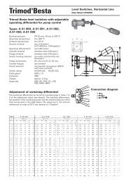
XIV. ContinuedE. Spindle RunoutIt is important that the spindle be kept very straight inorder to transmit the spring force to the disc without lateralbinding. Overgagging is one of the common causes ofbent spindles. A method to check the essential workingsurfaces of the spindle is illustrated in Figure 10 below.AATable 7: Spindle Critical DimensionsC maxOrificein.mmH .004 0.10J .004 0.10K .007 0.18L .007 0.18M .007 0.18N .007 0.18P .007 0.18Q .007 0.18F. Spring and Spring WashersCB45 0Figure 10: Spindle Check StandUsing a spindle check stand (see Figure 10 as a reference),place the ball end of the spindle into a depression at thebase “B” of the stand. Lean the upper portion of thespindle against the “V” block. It should be touching thespindle just below the threads on the upper portion of thespindle. Using a machinists indicator on a 45° angle atspindle shoulder "C", rotate the spindle and read the TotalIndicator Run out on the indicator. If the TIR is less thanvalues shown in Table 7, the spindle may be returned toservice. If the TIR is greater than these values, straightenthe spindle using "V" blocks and a hydraulic press untilthe TIR is found to be acceptable.Other parts of the spindle not used as working surfacesmay run out considerably more than .007” (0.18 mm), butthis should not be regarded as unacceptable. Althoughthe upper thread end is not a working surface, excessivebending in this area could effect the accuracy of theDresser Consolidated ® Hydroset device, and/or theDresser Consolidated ® Electronic Valve Tester, if either ofthese devices is used to verify valve set pressure.Spring wire that is irregularly spaced, or the ends are notparallel, are sufficient causes for replacement. The springwashers are machined to fit the ends of the spring -there should be no more than a .030 inches clearancebetween the spring and the spring washer. If a spring isbadly damaged by corrosion (flaking, pitting, or reductionin wire diameter), replace the spring with the properspring. If the spring is unable to be identified contact theDresser Consolidated ® Field Service Department at (318)640-6055.G. Lift RestrictorOn <strong>1511</strong> valves with set pressures of 26 psig (1.79 barg)and below will have a Lift Restrictor installed on thespindle stem, located inside the spring. Measure to verifyminimum length for the appropriate orifice as per Table 8.If under the minimum length, replace the Lift Restrictor.Table 8: Lower Pressure Lift StopOrificeL minin.mmH 2.25 57.0J 2.25 57.0K 3.50 88.8L 3.50 88.8M 3.50 88.9N 3.50 88.9P 3.94 100.0Q 5.00 127.020 | Dresser Consolidated ®
XV. ReassemblyDuring reassembly, three items are of extreme importance.They are:1) Alignment2) Cleanliness3) LubricationTo achieve the correct alignment, the bearing surfacesof the compression screw/upper spring washer, spindle/lower spring washer and spindle to disc pocket shouldeach be ground together to attain a perfect match. Thisis done by applying a lapping and grinding compoundof about 500 grit on one of the surfaces and rubbingthem together until a smooth unbroken contact point isestablished on both surfaces.All bearing surfaces and threaded areas must be lubricatedusing a high quality high temperature lubricant. At thefactory, Nickel-Ease is used and is recommended. Forenvironments where corrosion is a problem, contact thefactory field service department for suggestions on specialcoating or plating procedures which will protect the parts.1. Thread the lower ring onto the seat bushing and turn itdown until it is below the seating surface. (This allowsthe disc to rest on the bushing without interferencefrom the ring).2. Thread the upper ring/guide into the valve bodyreestablishing its original relationship to the bushing,as measured in Section XII, Disassembly for Repair,step 2. Insert the upper adjusting ring pin into thevalve and tighten. The ring should now be able torock back and forth but not turn. If position is notknown, refer to Section XI.3. After inspecting both the disc and bushing seat forcleanliness, thread the spindle into the disc andinsert the disc gently into the valve until it rests on thebushing.4. Place the spring and spring washers onto the spindle.5. Place the yoke over the spindle and replace the capscrews or nuts. Care must be taken to tighten the yokedown evenly to prevent distortion and misalignment.6. Thread the compression screw into the yoke,reestablish the original relationship betweencompression screw and spindle, as measured inSection XII, Disassembly for Repair, Step 6. Thentighten the compression screw lock nut.7. Raise the lower ring until it contacts the disc thenlower it the number of notches needed to reestablishits original relationship to the disc, as measured inSection XII, Disassembly for Repair, step 2. Threadthe lower adjusting ring pin into the body and tighten.The ring should be free to rock back and forth but notturn. If position is not known, refer to Section XI.8. Thread the release nut onto the spindle and replacethe cap, lever and lever pin. Adjust the release nut sothere is from 0.125” (3.18 mm) to 0.063” (1.59 mm)clearance between the release nut and lever. Removethe lever pin, lever and cap, replace the lock nutor cotter pin, and tighten it against the release nut.Replace the cap, lever, lever pin and cotter pin andtighten the set screw. The valve is now ready forsetting and testing.XVI. Steam Testing Procedures1. Remove the caps on all valves to be set on the steamdrum and main steam line, or other pressure vessel.2. Install a “verified calibrated” pressure gauge on thedrum near the valves being set. When the main steamline valves are to be set, install the calibrated guageto read line pressure upstream of the valves to betested.3. After the pressure in the boiler has increased to 80%of the operating pressure, install gags on all valvesexcept the high set valve. Gags should be installedhand tight (no wrenches or mechanical force).4. Examine the nameplate on the high set valve. Thesymbol that is present on the nameplate will indicatethe proper standard of operation, as described inTable 9.During reassembly, the adjusting rings andcompression screw should be reset as they wereprior to disassembly. (If the correct adjusting ringspositions are not known, the adjusting rings shouldbe preset according to instructions in Section XI)Before attempting to make ring adjustments on avalve under pressure, gag the valve.<strong>1511</strong> <strong>Series</strong> Safety Valve (July/2010) | 21