DTC C0273/13 OPEN CIRCUIT IN ABS MOTOR ... - Highlander Club
DTC C0273/13 OPEN CIRCUIT IN ABS MOTOR ... - Highlander Club
DTC C0273/13 OPEN CIRCUIT IN ABS MOTOR ... - Highlander Club

You also want an ePaper? Increase the reach of your titles
YUMPU automatically turns print PDFs into web optimized ePapers that Google loves.
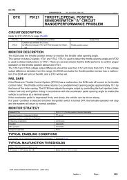
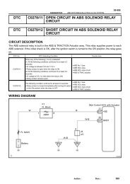
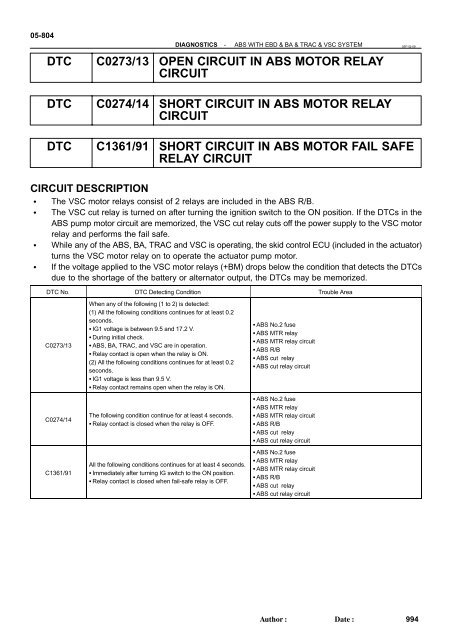
05-804DIAGNOSTICS-<strong>ABS</strong> WITH EBD & BA & TRAC & VSC SYSTEM<strong>DTC</strong> <strong>C0273</strong>/<strong>13</strong> <strong>OPEN</strong> <strong>CIRCUIT</strong> <strong>IN</strong> <strong>ABS</strong> <strong>MOTOR</strong> RELAY<strong>CIRCUIT</strong>05F1Q-09<strong>DTC</strong> C0274/14 SHORT <strong>CIRCUIT</strong> <strong>IN</strong> <strong>ABS</strong> <strong>MOTOR</strong> RELAY<strong>CIRCUIT</strong><strong>DTC</strong> C<strong>13</strong>61/91 SHORT <strong>CIRCUIT</strong> <strong>IN</strong> <strong>ABS</strong> <strong>MOTOR</strong> FAIL SAFERELAY <strong>CIRCUIT</strong><strong>CIRCUIT</strong> DESCRIPTIONThe VSC motor relays consist of 2 relays are included in the <strong>ABS</strong> R/B.The VSC cut relay is turned on after turning the ignition switch to the ON position. If the <strong>DTC</strong>s in the<strong>ABS</strong> pump motor circuit are memorized, the VSC cut relay cuts off the power supply to the VSC motorrelay and performs the fail safe.While any of the <strong>ABS</strong>, BA, TRAC and VSC is operating, the skid control ECU (included in the actuator)turns the VSC motor relay on to operate the actuator pump motor.If the voltage applied to the VSC motor relays (+BM) drops below the condition that detects the <strong>DTC</strong>sdue to the shortage of the battery or alternator output, the <strong>DTC</strong>s may be memorized.<strong>DTC</strong> No. <strong>DTC</strong> Detecting Condition Trouble Area<strong>C0273</strong>/<strong>13</strong>C0274/14C<strong>13</strong>61/91When any of the following (1 to 2) is detected:(1) All the following conditions continues for at least 0.2seconds. IG1 voltage is between 9.5 and 17.2 V. During initial check. <strong>ABS</strong>, BA, TRAC, and VSC are in operation. Relay contact is open when the relay is ON.(2) All the following conditions continues for at least 0.2seconds. IG1 voltage is less than 9.5 V. Relay contact remains open when the relay is ON.The following condition continue for at least 4 seconds. Relay contact is closed when the relay is OFF.All the following conditions continues for at least 4 seconds. Immediately after turning IG switch to the ON position. Relay contact is closed when fail-safe relay is OFF. <strong>ABS</strong> No.2 fuse <strong>ABS</strong> MTR relay <strong>ABS</strong> MTR relay circuit <strong>ABS</strong> R/B <strong>ABS</strong> cut relay <strong>ABS</strong> cut relay circuit <strong>ABS</strong> No.2 fuse <strong>ABS</strong> MTR relay <strong>ABS</strong> MTR relay circuit <strong>ABS</strong> R/B <strong>ABS</strong> cut relay <strong>ABS</strong> cut relay circuit <strong>ABS</strong> No.2 fuse <strong>ABS</strong> MTR relay <strong>ABS</strong> MTR relay circuit <strong>ABS</strong> R/B <strong>ABS</strong> cut relay <strong>ABS</strong> cut relay circuitAuthor:Date:994
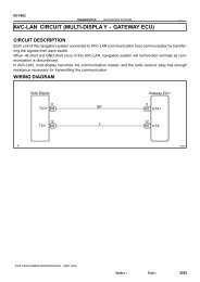
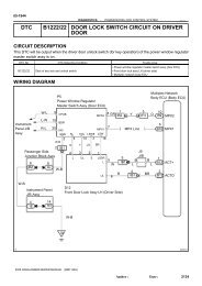
DIAGNOSTICS-<strong>ABS</strong> WITH EBD & BA & TRAC & VSC SYSTEM05-805WIR<strong>IN</strong>G DIAGRAM<strong>ABS</strong> R/BB-OSkid Control ECU with Actuator45S27 R+B-OB<strong>ABS</strong> MTR Relay51 2555 35LGW-L15S272S27MRBM<strong>ABS</strong> CUT Relay53 5551 25B-RG-R14S27MRFFL MA<strong>IN</strong>W1F7FL Block<strong>ABS</strong>29BatteryF46308Author:Date:995
05-806DIAGNOSTICS-<strong>ABS</strong> WITH EBD & BA & TRAC & VSC SYSTEM<strong>IN</strong>SPECTION PROCEDUREH<strong>IN</strong>T:Start the inspection from step 1 when using the hand-held tester and start from step 2 when not using thehand-held tester.(a)(b)(c)(d)1 PERFORM ACTIVE TEST BY HAND-HELD TESTER(<strong>ABS</strong> <strong>MOTOR</strong> RELAYOPERATION)Connect the hand-held tester to the DLC3.Start the engine.Select the ACTIVE TEST mode on the hand-held tester.Check the operation sound of the <strong>ABS</strong> motor individually when operating it with the hand-held tester.Item Vehicle Condition / Test Details Vehicle Condition / Test Details<strong>ABS</strong> MOT RELAY <strong>ABS</strong> motor relay / ON or OFF ON : Motor relay ONOKOK:The operation sound of the <strong>ABS</strong> motor should be heard.NG Go to step 2REPLACE <strong>ABS</strong> & TRACTION ACTUATOR ASSY (SEE PAGE 32-37 )2 <strong>IN</strong>SPECT FUSE(<strong>ABS</strong>2 FUSE)FL BLOCK(a)(b)Remove <strong>ABS</strong>2 fuse from the FL BLOCK.Check continuity of <strong>ABS</strong>2 fuse.Standard:<strong>ABS</strong> No.1 fuseBelow 1Ω (Continuity)<strong>ABS</strong>2F40458NGCHECK FOR SHORT <strong>IN</strong> ALL HARNESS ANDCONNECTOR CONNECTED TO FUSE ANDREPLACE FUSEOKAuthor:Date:996
DIAGNOSTICS-<strong>ABS</strong> WITH EBD & BA & TRAC & VSC SYSTEM05-8073 CHECK TERM<strong>IN</strong>AL VOLTAGE(VSC <strong>MOTOR</strong> RELAY 5 TERM<strong>IN</strong>AL OF <strong>ABS</strong> R/B)<strong>ABS</strong> R/B:5(a)(b)(c)Remove the VSC MTR relay from the <strong>ABS</strong> R/B.Turn the ignition switch to the ON position.Measure the voltage according to the value(s) in the tablebelow.Standard:Tester ConnectionSpecified ConditionTerminals 5 - Body ground10 to 14 VI37487NG REPAIR OR REPLACE HARNESS ORCONNECTOROK4 <strong>IN</strong>SPECT VSC <strong>MOTOR</strong> RELAY(a)Measure the resistance according to the value(s) in thetable below.Standard:Tester Connection Connection Specified resistance3 - 5 Always3 - 5Apply B+ between terminal1 and 210 kΩ or higher (No continuity)Below 1 ΩB57491NGREPLACE VSC <strong>MOTOR</strong> RELAYOK5 <strong>IN</strong>SPECT VSC CUT RELAY(a)Measure the resistance according to the value(s) in thetable below.Standard:Tester Connection Connection Specified resistance3 - 5 Always3 - 5Apply B+ between terminal1 and 210 kΩ or higher (No continuity)Below 1 ΩB16200NOREPLACE VSC CUT RELAYOKAuthor:Date:997
05-808DIAGNOSTICS-<strong>ABS</strong> WITH EBD & BA & TRAC & VSC SYSTEM6 CHECK HARNESS AND CONNECTOR(VSC <strong>MOTOR</strong> RELAY - SKID CONTROLECU)Skid Control ECU(harness side connector)BMS27(a)(b)Disconnect the skid control ECU connector.Measure the resistance according to the value(s) in thetable below.Standard:Tester ConnectionSpecified ConditionS27-2 (BM) - 3 (<strong>ABS</strong> R/B) Below 1 Ω(c)Measure the resistance according to the value(s) in thetable below.Standard:<strong>ABS</strong> R/B:Tester ConnectionSpecified ConditionS27-2 BM - Body ground 10 kΩ or higher3I37488NG REPAIR OR REPLACE HARNESS ORCONNECTOROK7 CHECK HARNESS AND CONNECTOR(VSC <strong>MOTOR</strong> RELAY - SKID CONTROLRELAY)<strong>ABS</strong> R/B:5(a)(b)Remove the <strong>ABS</strong> motor relay and skid control relay from<strong>ABS</strong> R/B.Measure the resistance according to the value(s) in thetable below.Standard:Tester ConnectionSpecified Condition35 (<strong>ABS</strong> <strong>MOTOR</strong> Relay) -3 (Skid Control Relay)Below 1 ΩI37487NG REPAIR OR REPLACE HARNESS ORCONNECTOROKREPLACE <strong>ABS</strong> & TRACTION ACTUATOR ASSY (SEE PAGE 32-37 )Author:Date:998