POE-D10-00-E-11-X1Y1Y5P Y5U Y5V CH SL
POE-D10-00-E-11-X1Y1Y5P Y5U Y5V CH SL
POE-D10-00-E-11-X1Y1Y5P Y5U Y5V CH SL

You also want an ePaper? Increase the reach of your titles
YUMPU automatically turns print PDFs into web optimized ePapers that Google loves.
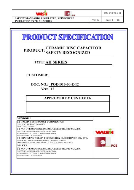
<strong>POE</strong>-<strong>D10</strong>-<strong>00</strong>-E-12SAFETY STANDARDS REGULATED, REINFORCEDINSULATION TYPE, AH SERIESVer: 12 Page: 1 / 18PRODUCT:CERAMIC DISC CAPACITORSAFETY RECOGNIZEDTYPE: AH SERIESCUSTOMER:DOC. NO.: <strong>POE</strong>-<strong>D10</strong>-<strong>00</strong>-E-12Ver.: 12APPROVED BY CUSTOMERVENDOR:□ WALSIN TE<strong>CH</strong>NOLOGY CORPORATION566-1, KAO SHI ROAD,YANG-MEITAO-YUAN, TAIWAN□ PAN OVERSEAS (GUANGZHOU) ELECTRONIC CO.,LTD.NO.277,HONG MING ROAD,EASTERN SECTION,GUANG ZHOU ECONOMIC AND TE<strong>CH</strong>NOLOGYDEVELOPMENT ZONE,<strong>CH</strong>INA□ DONGGUAN WALSIN TE<strong>CH</strong>NOLOGY ELECTRONICS CO., LTD.NO.638, MEI JING WEST ROAD,XINIUPO,ADMINISTRATIVEZONE,DALANGTOWN,DONGGUAN CITY, GUANGDONG PROVINCEMAKER:□ PAN OVERSEAS (GUANGZHOU) ELECTRONIC CO.,LTD.NO.277,HONG MING ROAD,EASTERN SECTION,GUANG ZHOU ECONOMIC AND TE<strong>CH</strong>NOLOGYDEVELOPMENT ZONE,<strong>CH</strong>INA
<strong>POE</strong>-<strong>D10</strong>-<strong>00</strong>-E-12SAFETY STANDARDS REGULATED, REINFORCEDINSULATION TYPE, AH SERIESVer: 12 Page: 2 / 18Record of changeDate Version Description page2<strong>00</strong>8.6.3 1 1.D22-<strong>00</strong>-E-01( before) → <strong>POE</strong>-<strong>D10</strong>-<strong>00</strong>-E-01(1 st edition)2<strong>00</strong>8.8.22 2 1 Complete lead code2. Add last SAP code “ H” for halogen and Pb free , epoxy resin..2<strong>00</strong>8.12.12 3 1. Complete the 13 th to 17 th codes of SAP P/N.2. Page layout adjustment.2<strong>00</strong>9.7.8 4 1 Change PSA & <strong>POE</strong> logo to Walsin & <strong>POE</strong> logo.2.Complete Marking statement.3.Revised standard NO. of SEV, SEMKO, FIMKO, NEMKO, DEMKO andKEMA.Revised recognized NO. of FIMKO, NEMKO, DEMKO and KEMA.2134-510122<strong>00</strong>9.9.14 5 1. H0: 18.0+2.0/-1.5 revised to 18.0+2.0/-02. “Protrusion length”: “+0.5to-1.0” revised to “2.0max (Or the end of leadwire may be inside the tape.)”3. Add “250V~” under the “UL” mark according to the product’s marking.2<strong>00</strong>9.12.24 6 1. Marking2. Correct X1 of recognized No by KTL.3. Revised the Figure of impulse voltage test(Item 7.3.14) according to thestandard IEC 60384-14 ed.34. Add “1AH” code for Y1:4<strong>00</strong>V marking type.20<strong>11</strong>.1.<strong>11</strong> 7 1. Review SAP P/N about diameter code:YU*AH561K1<strong>00</strong>*YU*AH561K080*2. Delete “AT” taping type.3. Add test item “Temperature Cycle ” .4. Add item 10 “Drawing of internal structure and material list”20<strong>11</strong>.5.12 8 1. Review the safety standards approval and recognized no.2. Delete “old P/N”3. Add the special marking for P/N:YP*AH102K1<strong>00</strong>2012.1.30 9 1. Review the approval rated voltage of UL and the marking. 8~9991010<strong>11</strong>14464,5,8,91419105~692012/4/6 10 In order to improve the traceability of the product, change the date code on 8capacitor body, new date code can trace back to production “Lot No.”2013/5/13 <strong>11</strong>1. Review the Lead diameter φ from 0.60 +0.1/-0.05mm to 0.55+/-0.05mm2. Add“3.1Norminal parts&3.2 special for surge parts” for “3. Partnumbering/T.C/Capacitance/ Tolerance/Diameter”3. In order the customer to know the round time of manufacture, change thedate code on capacitor body, new date code can know the month ofmanufacture.4. Delete “No marked with “ _” stand for Pb free”.5. Delete “When the TCC is <strong>Y5V</strong>(YV), there is a “F” between the “AH” andcapacitance code.”6. Review the Solderability time from 2 ±0.5s to 5±0.5s5,6,76888<strong>11</strong>1. Review the “Manufactured Date” to “Products ID” on the marking page2. Delete “The marking can be printed on either one side or two side of82013/10/16 12coating body.‛and add ‚for SAP part number 10-<strong>11</strong> digits ≤‘07’ 8products‛to two sides and ‚for SAP part number <strong>11</strong>-12 digits ⁋‘08 ’products‛to one side.
<strong>POE</strong>-<strong>D10</strong>-<strong>00</strong>-E-12SAFETY STANDARDS REGULATED, REINFORCEDINSULATION TYPE, AH SERIESVer: 12 Page: 3 / 18Table of ContentsNo. Item Page1 Part number for SAP system 4/182 Mechanical 5/183 Part numbering/T.C/Capacitance/ Tolerance/Diameter 6/184 Taping Format 7/185 Marking 8/186 Scope 9/187 Specification and test method 10/18~13/188 Packing specification 14/189 Notices 15/18~1/1810 Drawing of Internal Structure and material list 18/18
<strong>POE</strong>-<strong>D10</strong>-<strong>00</strong>-E-12SAFETY STANDARDS REGULATED, REINFORCEDINSULATION TYPE, AH SERIESVer: 12 Page: 4 / 181. Part number for SAP system:(Ex.) YU 0AH 472 M 13 0 L 20 C 0 B(1) (2) (3) (4) (5) (6) (7) (8) (9) (10) (<strong>11</strong>)(1)Temperature characteristic (identified code)CODE <strong>CH</strong>(NP0) <strong>SL</strong> YP (Y5P) YV(<strong>Y5V</strong>) YU (<strong>Y5U</strong>)Cap. Change0±60PPM/℃-1<strong>00</strong>0~+350PPM/℃(+20 ℃ ~+85 ℃ )(2)TYPE (identified by 3-figure code):0AH = AH Type(X1:4<strong>00</strong>V~/Y1:250V~),1AH=AH Type(X1:4<strong>00</strong>V~/Y1:4<strong>00</strong>V~)(3)Capacitance (identified by 3-figure code):EX.221=220pF±10% -80% ~ +30% -55% to +20%(4)Capacitance tolerance (identified by code): C:±0.25pF,D:±0.5pF,J:±5%,K:±10%,M:±20%(5)Nominal body diameter dimension (identified by 2-figure code):06--Dmax7.0mm, 07--Dmax8.0mm...(6)Internal code: 0--Normal, other code--Special control(7)Lead Style:Refer to “2. Mechanical”.(8)Packing mode and lead length (identified by 2-figure code)Taping CodeAMDescriptionAmmo box and product pitch:25.4 mmBulk CodeDescription3ELead length : 3.5mm04 Lead length : 4.0mm4ELead length : 4.5mm20 Lead length : 20mm(9)Length tolerance(10)PitchCodeABCDDescription±0.5 mm(only for kink lead type)±1.0 mmMin.Taping special purposeCodeDescription0 10±1 mmA10±0.5 mm(<strong>11</strong>)Epoxy Resin CodeCodeBHDescriptionPb free, Epoxy ResinHalogen and Pb free, epoxy resin.
<strong>POE</strong>-<strong>D10</strong>-<strong>00</strong>-E-12SAFETY STANDARDS REGULATED, REINFORCEDINSULATION TYPE, AH SERIES2. Mechanical:Encapsulation:Epoxy resin, flammability UL94 V-0Available lead code (unit: mm):Lead type SAP P/N(13-17)digitsPitch(F)LeadLength (L)PackingVer: 12 Page: 5 / 18Lead ConfigurationLead style:LType LStraight longleadL20C0 10 ± 1.0 20 min. BulkLead style:BType BStraight longleadBAMD0 10 ± 1.0Refer to “4.Tapingformat”Tap.AmmoLead style:LType LStraight shortleadL03B0 10 ± 1.0 3.0 ± 1.0L4EB0 10 ± 1.0 4.5 ± 1.0L05B0 10 ± 1.0 5.0 ± 1.0BulkLead style:DType DVertical kinkleadLead style:XType XOutside kink leadD3EA0 10 ± 1.0 3.5 ± 0.5D04A0 10 ± 1.0 4.0 ± 0.5DAMD0 10 ± 1.0Refer to “4.Tapingformat”X3EA0 10 ± 1.0 3.5 ± 0.5X04A0 10 ± 1.0 4.0 ± 0.5X05B0 10 ± 1.0 5.0 ± 1.0XAMD0 10 ± 1.0Refer to “4.Tapingformat”BulkTap.AmmoBulkTap.Ammo* Lead diameter Φd: 0.55 +/-0.05mm*e (Coating extension on leads): 3.0mmMax for straight lead lead style, not exceed the kink for kink lead.
<strong>POE</strong>-<strong>D10</strong>-<strong>00</strong>-E-12SAFETY STANDARDS REGULATED, REINFORCEDINSULATION TYPE, AH SERIESVer: 12 Page: 6 / 183. Part numbering/T.C/Capacitance/ Tolerance/Diameter:3.1 Normal parts:SAP P/N T.C. Capacitance(pF) ToleranceDimension (unit:mm)D(max.) T(max.) F Φd<strong>CH</strong>*AH***C060* 2, 3,4, 5(pF) ±0.25pF 7.0<strong>CH</strong>*AH***D060* <strong>CH</strong> 6,7,8,9,10(pF) ±0.5pF 7.0<strong>CH</strong>*AH120J060* (NP0) 12 7.0<strong>CH</strong>*AH***J070* 15,18,20,22,24,27(pF) 8.0<strong>SL</strong>*AH***J060*15,18,20,22,24,27,30,33, 36, 39(pF) ±5%7.0<strong>SL</strong>*AH***J070* <strong>SL</strong>* 47,50,51, 56,62(pF) 8.0<strong>SL</strong>*AH***J080* 68,75,82(pF) 9.0<strong>SL</strong>*AH101J090*1<strong>00</strong>pF10.0 5.0 10±1 0.55+/-0.05YP*AH101K060* 1<strong>00</strong> pF 7.0YP*AH151K060* 150 pF 7.0YP*AH221K060* 220 pF 7.0YP*AH331K060*Y5P330 pF±10%7.0YP*AH471K070* 470 pF 8.0YP*AH561K080* 560 pF 9.0YP*AH681K080* 680 pF 9.0YP*AH102K1<strong>00</strong>*1<strong>00</strong>0 pF<strong>11</strong>.0YU*AH102M070* 1<strong>00</strong>0 pF 8.0YU*AH152M080* 15<strong>00</strong> pF 9.0YU*AH222M090* 22<strong>00</strong> pF 10.0<strong>Y5U</strong>YU*AH332M<strong>11</strong>0* 33<strong>00</strong> pF 12.05.0YU*AH392M120* 39<strong>00</strong> pF 14.0YU*AH472M130*47<strong>00</strong> pF ±20% 14.010±1 0.55+/-0.05YV*AH102M060* 1<strong>00</strong>0pF 7.0YV*AH152M070* 15<strong>00</strong>pF 8.0YV*AH222M080* <strong>Y5V</strong> 22<strong>00</strong>pF 9.0 5.5YV*AH332M1<strong>00</strong>* 33<strong>00</strong>pF <strong>11</strong>.0YV*AH472M<strong>11</strong>0*47<strong>00</strong>pF12.0The minimum thickness of coating (reinforced insulation) is 0.4mm.3.2 Special for surge parts:Part NumberTemp.Dimension (mm)Cap.(pF) Tol.Char.D(max.) T (max.) F±1 Wire Dia. (φd)YP *AH101K06S* 1<strong>00</strong> 7.0YP *AH151K06S* 150 7.0YP *AH221K06S* 220 7.0YP *AH331K07S* Y5P 330 ±10% 8.0 6.0 10.0 0.55+/-0.05YP *AH471K08S* 470 9.0YP *AH681K09S* 680 10.0YP *AH102K<strong>11</strong>S*1<strong>00</strong>012.0YU*AH102M07S* 1<strong>00</strong>0 8.0YU*AH152M08S* 15<strong>00</strong> 9.0YU*AH222M09S* 22<strong>00</strong> 10.0<strong>Y5U</strong>±20%YU*AH332M<strong>11</strong>S* 33<strong>00</strong> 12.06.0 10.0 0.55+/-0.05YU*AH392M12S* 39<strong>00</strong> 14.0YU*AH472M13S*47<strong>00</strong>14.0surges.The special parts only improve surge withstanding, but can’t independently be used in protecting application against
<strong>POE</strong>-<strong>D10</strong>-<strong>00</strong>-E-12SAFETY STANDARDS REGULATED, REINFORCEDINSULATION TYPE, AH SERIESVer: 12 Page: 7 / 184. Taping Format:Part number: □□0AH□□□□□□□□□AMD□B<strong>POE</strong> Part Number*BAMD0 / *DAMD0 / *XAMD0Item Symbol Dimensions(mm)Pitch of component P 25.4 ± 2Pitch of sprocket P0 12.7 ± 0.3Lead spacing F 10.0 ± 1.0Length from hole center to componentcenterP2 12.7 ± 1.5Length from hole center to lead P1 7.7 ± 1.5Body diameter D See the “3. Part numbering/T.C/Capacitance/ Tolerance/Diameter”Deviation along tape, life or right △ S0 ± 2.0Carrier tape width W 18.0 +1/ -0.5Position of sprocket hole W1 9.0 ± 0.5Lead distance between the kink and18.0 +2.0/-0H0center of sprocket hole(For: *DAMD0 & *XAMD0)Lead distance between the bottom of20.0+1.5/-1.0Hbody and the center of sprocket hole(For: *BAMD0)Protrusion length2.0max (Or the end of lead wire may be inside the tape.)Diameter of sprocket hole D0 4.0 ± 0.2Lead diameter φd 0.55 ±0.05Total tape thickness t1 0.6 ± 0.3Total thickness, tape and lead wire t2 1.5 max.Deviation across tape△ h12.0 max.△ h22.0 maxPortion to cut in case of defect L <strong>11</strong>.0 max.Hole-down tape width W0 8.0 minHole-down tape distortion W2 1.5 ± 1.5Coating extension on leads e 3.0 max for straight lead style; Not exceed the kink leads for kink lead.Body thickness T See the “3. Part numbering/T.C/Capacitance/ Tolerance/Diameter”
<strong>POE</strong>-<strong>D10</strong>-<strong>00</strong>-E-12SAFETY STANDARDS REGULATED, REINFORCEDINSULATION TYPE, AH SERIESVer: 12 Page: 8 / 185. Marking:1.Type Designation2.Nominal Capacitance3.Capacitance Tolerance4.Company Name Code(Trade mark)AH5. Products ID Abbreviation ex.:3-digit-systemC:±0.25pF,D:±0.5pF,J:±5%,K:±10%,M:±20%6.Approved Monogram:(1) VDE approval markIEC 60384-14 3rd (2<strong>00</strong>5).Class Code:X1:4<strong>00</strong>V~,Y1:250V~ or4<strong>00</strong>V~(2) UL approval mark (6) DEMKO approval mark(3) CSA approval mark (7) FIMKO approval mark(4) SEMKO approval mark(8) SEV approval mark(5) NEMKO approval mark (9) CQC approval markNormal markingTwo sidesOne side(for SAP part number 10-<strong>11</strong> (for SAP part number 10-<strong>11</strong>digits ≤“07”products) digits ⁋‚0808” products)0AHYP*AH102K*****(Special marking)1AH* Marking by the laser.*“C”:Marked with code “ _ ” stand for Halogen and Pb free epoxy resin.
<strong>POE</strong>-<strong>D10</strong>-<strong>00</strong>-E-12SAFETY STANDARDS REGULATED, REINFORCEDINSULATION TYPE, AH SERIESVer: 12 Page: 9 / 186. Scope:THIS SPECIFICATION APPLIES TO CERAMIC INSULATED CAPACITORS DISK TYPE USEDIN ELECTRONIC EQUIPMENT.6.1Applicable safety standardThis specification applies to the VDE, SEV, SEMKO, FIMKO, NEMKO, DEMKO, KEMA, KTL,UL, CSA approved ceramic capacitors disc type for antenna coupling, line-by-pass andacross-the-line. X1, Y1 capacitor based on IEC384-14 3rd edition. "UL, CSA recognized capacitorfor across-the-line, line-by-pass" and antenna-isolation.6.2 Safety standards approval and recognized no.SafetyStandardULCSAVDE(ENEC)SEVSEMKOStandard No. Subclass w.v. Recognized No.ANSI/UL X1 4<strong>00</strong>VAC60384-14:2<strong>00</strong>9 Y1 250VAC/4<strong>00</strong>VACCAN/CSA X1 4<strong>00</strong>VACE60384-14:2<strong>00</strong>9 Y1 250VAC/4<strong>00</strong>VACIEC60384-14 X1 4<strong>00</strong>VAC(ed.3) 2<strong>00</strong>5 Y1 250VAC/4<strong>00</strong>VACIEC 60384-14: X1 4<strong>00</strong>VAC(ed3)2<strong>00</strong>5 Y1 250VAC/4<strong>00</strong>VACIEC 60384-14: X1 4<strong>00</strong>VAC(ed3)2<strong>00</strong>5 Y1 250VAC/4<strong>00</strong>VACE14654423479714<strong>00</strong>01804<strong>11</strong>.0325<strong>11</strong>10795FIMKONEMKODEMKODEKRA(KEMA)IEC 60384-14: X1 4<strong>00</strong>VAC(ed3)2<strong>00</strong>5 Y1 250VAC/4<strong>00</strong>VACIEC 60384-14: X1 4<strong>00</strong>VAC(ed3)2<strong>00</strong>5 Y1 250VAC/4<strong>00</strong>VACIEC 60384-14: X1 4<strong>00</strong>VAC(ed3)2<strong>00</strong>5 Y1 250VAC/4<strong>00</strong>VACIEC 60384-14: X1 4<strong>00</strong>VAC(ed3)2<strong>00</strong>5 Y1 250VAC/4<strong>00</strong>VACNCS/FI 24755No.P<strong>11</strong>214078D-<strong>00</strong>0382150105.02GB/T X1:4<strong>00</strong>VAC /Y1:4<strong>00</strong>VACCQC03<strong>00</strong>1<strong>00</strong>3673CQC14472-1998 X1:4<strong>00</strong>VAC /Y1:250VAC CQC<strong>11</strong><strong>00</strong>1055510X1 4<strong>00</strong>VAC SU03017-4<strong>00</strong>4BKTL K60384-14Y1 250VAC SU03017-4<strong>00</strong>3A
<strong>POE</strong>-<strong>D10</strong>-<strong>00</strong>-E-12SAFETY STANDARDS REGULATED, REINFORCEDINSULATION TYPE, AH SERIESVer: 12 Page: 10 / 187. Specification and test method:7.1 Operating Temperature Range: -25 to +125°C7.2 Test condition:Test and measurement shall be made at the standard condition. (temperature 15~35 ℃ , relative humidity 45~75%and atmospheric pressure 860~1060hpa). Unless otherwise specified herein.If doubt occurred on the value of measurement, and measurement was requested by customer capacitors shall bemeasured at the reference condition. (temperature 20±2℃ or25 ± 2 ℃ , relative humidity 60~70% and atmosphericpressure 860~1060hpa.)7.3 Performance:No Items Performance Testing methodAppearance The appearance and dimension Visual check.7.3.1And dimension shall be as given in section 3.The marking shall be easily Visual check.7.3.2 Markinglegible. (As given section 5)7.3.37.3.4WithstandvoltageInsulationResistanceBetweenterminalsBodyInsulationBetweenterminalsNo failure.No failure.1<strong>00</strong><strong>00</strong>MΩ or more.7.3.5 Capacitance Within specified tolerance.7.3.67.3.7DissipationFactor(tanδ) or QTemperatureCharacteristic7.3.8 Solderability of LeadsY5P、<strong>Y5U</strong>:D.F. ≦ 2.5%<strong>Y5V</strong>:D.F. ≦ 5.0%<strong>CH</strong>&<strong>SL</strong>:30pF&above: ≧ 1<strong>00</strong>0Below 30PF: ≧ 4<strong>00</strong>+20×CChar. Capacitance ChangeY5P Within ± 10%0<strong>Y5U</strong> Within ± 2 55 %<strong>Y5V</strong> Within –80 ~ +30%<strong>CH</strong> 0±60ppm/℃-1<strong>00</strong>0~+350<strong>SL</strong> ppm/℃(+20 ℃ ~+85℃)Lead wire should besoldered with uniformcoating on the axialdirection over 3/4 of thecircumferential direction.The capacitors shall not be damage when AC4<strong>00</strong>0V(rms.) are applied between the lead wires for 60sec.First. The terminals of the capacitor shall be closelywrapped around the body of the capacitor distance ofabout 3 to 4mm from each terminal. Then, thecapacitor shall be inserted into a container filled withmetal balls of about 1mm diameter. Finally, AC4<strong>00</strong>0V(rms.) is applied for 60sec between the capacitor leadwires and metal balls.The insulation resistance shall be measured withDC5<strong>00</strong>±50V within 60±5sec of charging.Y5P&<strong>Y5U</strong>&<strong>Y5V</strong>: The capacitance shall be measuredat 20±2 ℃ with 1kHz±20% and 5V(rms.) or less.<strong>CH</strong>&<strong>SL</strong>: The capacitance shall be measured at 25 ℃with 1MHz±20% and1.0±0.2VrmsThe capacitance measurement shall be made at eachstep specified in Table 1.Table 1Step Temperature (℃)1 +20±22 -25±23 +20±24 +85±25 +20±2Pre-treatment:Capacitor shall be stored at 85±2 ℃ for 1hour, then1placed at※ room condition for 24±2hours beforemeasurements.The lead wire of capacitor should be dipped intomolten solder for 5 ± 0.5 sec.The depth of immersion is up to about 1.5 to 2.0 mmfrom the root of lead wires.Temp. of solder:Lead Free Solder ( Sn-3Ag-0.5Cu)245±5℃
<strong>POE</strong>-<strong>D10</strong>-<strong>00</strong>-E-12SAFETY STANDARDS REGULATED, REINFORCEDINSULATION TYPE, AH SERIESVer: 12 Page: <strong>11</strong> / 18No Items Performance Testing method7.3.9 RobustnessofTerminationsTensileBendingLead wire shall not cut off.Capacitor shall not bebroken.Lead wire shall not cut off.Capacitor shall not bebroken.Appearance No marked defect.I.R.DielectricStrength1<strong>00</strong>0 MΩ min.Per item7.3. 3With the termination in its normal position, the specimen isheld by its body in such a manner that the axis of thetermination is vertical; the tensile force of 10N shall beapplied to the termination in the direction of its axis andacting in a direction away from the body of the specimen.With the termination in its normal position, the specimen isheld by its body in such a manner that the axis of thetermination is vertical; a mass applying a force of 5N is thensuspended from the end of the termination. The body of thespecimen is then inclined, within a period of 2 to 3sec,through an angle of approximately 90 ∘ in the vertical planeand then returned to its initial position over the same periodof time; this operation constitutes one bend. One bendimmediately followed by a second bend in the oppositedirection.As shown in figure, the lead wires should be immersed insolder of 350 ± 10 ℃ or 260 ± 5 ℃ up to 1.5 to 2.0 mm fromthe root of terminal for 3.5 ± 0.5 sec ( 10 ± 1 sec. for 260 ± 5℃ ).7.3.10SolderingEffect(Non-Preheat)CapacitanceY5P,<strong>Y5U</strong>,<strong>Y5V</strong>:Within ±10 %<strong>SL</strong>,<strong>CH</strong>:Within±2.5%or±0.25pF,Whichever is large.Pre-treatment:Capacitor shall be stored at 85±2 ℃ for 1hour.then placed1at※ room condition for 24±2hours before initialmeasurements.Post-treatment:1Capacitor shall be stored for 1 to 2hours at※ roomcondition.Appearance No marked defect.First the capacitor should be stored at 120+0/-5 ℃ for 60+0/-5 sec.Then , as in figure , the lead wires should be immersed solderof 260+0/-5 ℃ up to 1.5 to 2.0 mm from the root of terminalfor 7.5+0/-1 sec.7.3.<strong>11</strong>SolderingEffect(On-Preheat)I.R.DielectricStrengthCapacitance1<strong>00</strong>0 MΩ min.Per item 7.3.3Y5P,<strong>Y5U</strong>,<strong>Y5V</strong>:Within ±10 %<strong>SL</strong>,<strong>CH</strong>:Within±2.5%or±0.25pF,Whichever is large.Pre-treatment:Capacitor shall be stored at 85±2 ℃ for 1hour.then placed1at※ room condition for 24±2hours before initialmeasurements.Post-treatment:1Capacitor shall be stored for 1 to 2hours at※ roomcondition.
<strong>POE</strong>-<strong>D10</strong>-<strong>00</strong>-E-12SAFETY STANDARDS REGULATED, REINFORCEDINSULATION TYPE, AH SERIESVer: 12 Page: 12 / 18No Items Performance Testing methodAppearance No marked defect.7.3.127.3.13Humidity(Under steadyState)HumidityLoadingCapacitanceD.F.QI.R.DielectricStrengthY5P: Within ±10%<strong>Y5U</strong>: Within ±20%<strong>Y5V</strong>: Within ±30%<strong>SL</strong>&<strong>CH</strong>:Within±2.5%or±0.25pF,Whichever is large.Y5P,<strong>Y5U</strong>:5.0% max.<strong>Y5V</strong>:7.5% max.<strong>SL</strong>&<strong>CH</strong>:Less than 30pF=>Q≧ 1<strong>00</strong>+10×C/3More than 30pF=>Q≧ 2<strong>00</strong>Y5P&<strong>Y5U</strong>&<strong>Y5V</strong>:3<strong>00</strong>0MΩ min.<strong>SL</strong>&<strong>CH</strong>: 1<strong>00</strong>0MΩ min.Per Item 7.3.3Appearance No marked defect.CapacitanceY5P&<strong>Y5U</strong>&<strong>Y5V</strong>:Within ±20%<strong>SL</strong>&<strong>CH</strong>:Within±3%or±0.3pF,Whichever is large.Set the capacitor for 5<strong>00</strong>±12hours at 40±2 ℃ in 90 to 95%relative humidity.1Then capacitor shall be stored for 1 to 2 hours at※ roomcondition.Apply the rated voltage for 5<strong>00</strong>±12 hours at 40±2 ℃ in90 to 95% relative humidity and set it for 1 to 2 hours1at※ room condition.Impulse VoltageEach individual capacitor shall be subjected to 8kVimpulses for three times. After the capacitors areapplied to life test.Fig. 2I.R.3<strong>00</strong>0MΩ min.<strong>SL</strong>&<strong>CH</strong>: 1<strong>00</strong>0MΩ min.7.3.14Life7.3.15 Flame TestDielectricStrengthPer Item 7.3 3The capacitor flamediscontinues as follows.Cycle Time1~4 30sec max.5 60sec max.The specimen capacitors are placed in a circulating airoven for a period of 1<strong>00</strong>0 hours. The air in the oven ismaintained at a temperature of125±3 ℃ . Throughout the test, the capacitors aresubjected to an AC425Vrms.(for 0AH type) orAC680Vrms.(for 1AH type) alternating voltage ofmains frequency, except that once each hour thevoltage is increased to AC1<strong>00</strong>0V(rms.) for 0.1 sec.The capacitor shall be subjected to applied for 15 secand then removed for 15 sec until 5 cycles.Fig. 5(unit: mm)
<strong>POE</strong>-<strong>D10</strong>-<strong>00</strong>-E-12SAFETY STANDARDS REGULATED, REINFORCEDINSULATION TYPE, AH SERIESVer: 12 Page: 13 / 18No Items Performance Testing methodThe specimens shall be individually wrapped in at least one butmore than two complete layers of cheesecloth. The specimens shallbe subjected to 20 discharges. The interval between successivedischarges shall be 5 sec. The UAC shall be maintained for 2 minafter the last discharge.Fig. 67.3.16ActiveFlammabilityThe cheesecloth shallnot be on fire.7.3.17 Passive FlammabilityThe burning timeshall not be exceededthe time 30 sec. Thetissue paper shall notignite.The capacitor under test shall be held in the position which bestpromotes burning. Each specimen shall only be exposed once toflame. Time of exposure to flame: 30sec.Length of flame : 12±1mmGas burner : Length 35mm min.Inside Dia. : 0.5±0.1mmOutside Dia. : 0.9mm max.Gas : Butane gas Purity 95% min.Fig. 77.3.18Temperature CycleAppearanceNo marked defectChar. Cap. DF / QChange<strong>SL</strong>, ≦±5% Q≧275+5/2C (C<strong>CH</strong>
<strong>POE</strong>-<strong>D10</strong>-<strong>00</strong>-E-12SAFETY STANDARDS REGULATED, REINFORCEDINSULATION TYPE, AH SERIESVer: 12 Page: 14 / 188.Packing Baggage:8.1 Packing size:BoxCartonBulkAmmotaping8.2 Packing quantity:Type of packing One bag One box One cartonBulk5<strong>00</strong>pcs 1<strong>00</strong>0pcs~2<strong>00</strong>0pcs 8<strong>00</strong>0pcs~16<strong>00</strong>0pcs2<strong>00</strong>pcs 1<strong>00</strong>0pcs 8<strong>00</strong>0pcsAmmo taping (AF-Product pitch:15.0mm) -- 1<strong>00</strong>0pcs 1<strong>00</strong><strong>00</strong>pcsAmmo taping (AM-Product pitch:25.4mm) -- 5<strong>00</strong>pcs 5<strong>00</strong>0pcs
<strong>POE</strong>-<strong>D10</strong>-<strong>00</strong>-E-12SAFETY STANDARDS REGULATED, REINFORCEDINSULATION TYPE, AH SERIESVer: 12 Page: 15 / 189. Notices:9.1 Caution (Rating):(1). Operating VoltageBe sure to maintain the Vp-p value of the applied voltage or the Vo-p which contains DC biaswithin the rated voltage range.When the voltage is started to apply to the circuit or it is stopped applying, the irregularvoltage may be generated for a transit period because of resonance or switching. Be sure touse a capacitor within rated voltage containing this irregular voltage.(2). Operating Temperature and Self-generated HeatKeep the surface temperature of a capacitor below the upper limit of its rated operatingtemperature range. Be sure to take into account the heat generated by the capacitor itself.When the capacitor is used in a high-frequency current, pulse current or the like, it may havethe self-generated heat due to dielectric-loss.Applied voltage should be the load such as self-generated heat is within 20 ℃ on thecondition of atmosphere temperature 25 ℃ . When measuring, use a thermocouple of smallthermal capacity-K of φ0.1mm and be in the condition where capacitor is not affected byradiant heat of other components and wind of surroundings. Excessive heat my lead todeterioration of the capacitor’s characteristics and reliability.(3). Test condition for withstanding VoltageI. Test EquipmentTest equipment for AC withstanding voltage shall be used with the performance of thewave similar to 50/60 Hz sine waves.If the distorted sine wave or over load exceeding the specified voltage value is applied, thedefective may be caused.
<strong>POE</strong>-<strong>D10</strong>-<strong>00</strong>-E-12SAFETY STANDARDS REGULATED, REINFORCEDINSULATION TYPE, AH SERIESVer: 12 Page: 16 / 18II.Voltage Applied MethodWhen the withstanding voltage is applied, capacitor’s lead or terminal shall be firmlyconnected to the output of the withstanding voltage test equipment, and then the voltageshall be raised from near zero to the test voltage.If the test voltage without the raise from near zero voltage would be applied directlyto capacitor, test voltage should be applied with the *zero cross. At the end of the testtime, the test voltage shall be reduced to near zero, and then capacitor's lead or terminalshall be taken off the output of the withstanding voltage test equipment.If the test voltage without the raise from near zero voltage would be applied directlyto capacitor, the surge voltage may arise, and therefore, the defective may be caused.ZERO CROSS is the point where voltage sine wavepass 0V.- See the right figure.(4). Fail-SafeWhen capacitor would be broken, failure may result in a short circuit. Be sure to provide anappropriate fail-safe function like a fuse on your product if failure would follow an electricshock, fire or fume.Failure to follow the above cautions may result, worst case, in a short circuit and cause fumingor partial dispersion when the product is used.9.2 Caution (Storage and operating condition):Operating and storage environmentThe insulating coating of capacitors does not form a perfect seal; therefore, do not use or storecapacitors in a corrosive atmosphere, especially where chloride gas, sulfide gas, acid, alkali, saltor the like are present. And avoid exposure to moisture. Before cleaning, bonding, or moldingthis product, verify that these processes do not affect product quality by testing the performanceof a cleaned, bonded or molded product in the intended equipment. Store the capacitors wherethe temperature and relative humidity do not exceed –10 to 40 degrees centigrade and 15 to 85%. Use capacitors within 6 months."Failure to follow the above cautions may result, worst case, in a short circuit and causefuming or partial dispersion when the product is used."9.3 Caution (Soldering and Mounting):9.3.1 Vibration and impact:Do not expose a capacitor or its leads to excessive shock or vibration during use.
<strong>POE</strong>-<strong>D10</strong>-<strong>00</strong>-E-12SAFETY STANDARDS REGULATED, REINFORCEDINSULATION TYPE, AH SERIESVer: 12 Page: 17 / 189.3.2 Soldering:When soldering this product to a PCB/PWB, do not exceed the solder heat resistancespecification of the capacitor. Subjecting this product to excessive heating could melt theinternal junction solder and may result in thermal shocks that can crack the ceramic element.When soldering capacitor with a soldering iron, it should be performed in followingconditions.Temperature of iron-tip: 4<strong>00</strong> degrees C. max.Soldering iron wattage: 50W max.Soldering time: 3.5 sec. max.9.3.3 Cleaning (ultrasonic cleaning):To perform ultrasonic cleaning, observe the following conditions.Rinse bath capacity: Output of 20 watts per liter or less.Rinsing time:5 min maximum.Do not vibrate the PCB/PWB directly.Excessive ultrasonic cleaning may lead to fatigue destruction of the lead wires."Failure to follow the above cautions may result, worst case, in a short circuit and causefuming or partial dispersion when the product is used."9.4 Caution (Handling):Vibration and impactDo not expose a capacitor or its leads to excessive shock or vibration during use."Failure to follow the above cautions may result, worst case, in a short circuit and causefuming or partial dispersion when the product is used."
<strong>POE</strong>-<strong>D10</strong>-<strong>00</strong>-E-12SAFETY STANDARDS REGULATED, REINFORCEDINSULATION TYPE, AH SERIESVer: 12 Page: 18 / 1810. Drawing of internal structure and material list:12345Remarks:No. Part name Material Model/Type Component1 Insulation Coating Epoxy polymer1.EF-150C2.EF-150(HF)3.PCE-2102.PCE-3<strong>00</strong>(HF)Epoxy resin、Pigment(Blue / UL 94 V-0 /)The minimum thickness of coating(reinforced insulation) is 0.4mm2 Dielectric Element Ceramic <strong>CH</strong>/<strong>SL</strong>/Y5P/<strong>Y5U</strong>/<strong>Y5V</strong> BaTiO 33 Solder Tin-silver Sn96.5-Ag3-Cu0.5 Sn96.5-Ag3-Cu0.54 Electrodes Ag5 Leads wireTinned copper cladsteel wire1.SP-160PL2.SP-260PL0.55±0.05mmSilver、Glass fritSubstrate metal: Fe & CuSurface plating: Sn 1<strong>00</strong>%(3~7µm)