POE-D10-00-E-11-X1Y1Y5P Y5U Y5V CH SL
POE-D10-00-E-11-X1Y1Y5P Y5U Y5V CH SL
POE-D10-00-E-11-X1Y1Y5P Y5U Y5V CH SL

You also want an ePaper? Increase the reach of your titles
YUMPU automatically turns print PDFs into web optimized ePapers that Google loves.
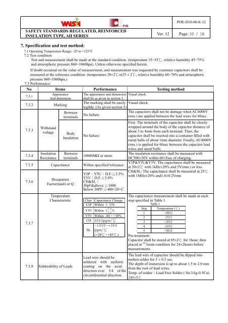
<strong>POE</strong>-<strong>D10</strong>-<strong>00</strong>-E-12SAFETY STANDARDS REGULATED, REINFORCEDINSULATION TYPE, AH SERIESVer: 12 Page: 10 / 187. Specification and test method:7.1 Operating Temperature Range: -25 to +125°C7.2 Test condition:Test and measurement shall be made at the standard condition. (temperature 15~35 ℃ , relative humidity 45~75%and atmospheric pressure 860~1060hpa). Unless otherwise specified herein.If doubt occurred on the value of measurement, and measurement was requested by customer capacitors shall bemeasured at the reference condition. (temperature 20±2℃ or25 ± 2 ℃ , relative humidity 60~70% and atmosphericpressure 860~1060hpa.)7.3 Performance:No Items Performance Testing methodAppearance The appearance and dimension Visual check.7.3.1And dimension shall be as given in section 3.The marking shall be easily Visual check.7.3.2 Markinglegible. (As given section 5)7.3.37.3.4WithstandvoltageInsulationResistanceBetweenterminalsBodyInsulationBetweenterminalsNo failure.No failure.1<strong>00</strong><strong>00</strong>MΩ or more.7.3.5 Capacitance Within specified tolerance.7.3.67.3.7DissipationFactor(tanδ) or QTemperatureCharacteristic7.3.8 Solderability of LeadsY5P、<strong>Y5U</strong>:D.F. ≦ 2.5%<strong>Y5V</strong>:D.F. ≦ 5.0%<strong>CH</strong>&<strong>SL</strong>:30pF&above: ≧ 1<strong>00</strong>0Below 30PF: ≧ 4<strong>00</strong>+20×CChar. Capacitance ChangeY5P Within ± 10%0<strong>Y5U</strong> Within ± 2 55 %<strong>Y5V</strong> Within –80 ~ +30%<strong>CH</strong> 0±60ppm/℃-1<strong>00</strong>0~+350<strong>SL</strong> ppm/℃(+20 ℃ ~+85℃)Lead wire should besoldered with uniformcoating on the axialdirection over 3/4 of thecircumferential direction.The capacitors shall not be damage when AC4<strong>00</strong>0V(rms.) are applied between the lead wires for 60sec.First. The terminals of the capacitor shall be closelywrapped around the body of the capacitor distance ofabout 3 to 4mm from each terminal. Then, thecapacitor shall be inserted into a container filled withmetal balls of about 1mm diameter. Finally, AC4<strong>00</strong>0V(rms.) is applied for 60sec between the capacitor leadwires and metal balls.The insulation resistance shall be measured withDC5<strong>00</strong>±50V within 60±5sec of charging.Y5P&<strong>Y5U</strong>&<strong>Y5V</strong>: The capacitance shall be measuredat 20±2 ℃ with 1kHz±20% and 5V(rms.) or less.<strong>CH</strong>&<strong>SL</strong>: The capacitance shall be measured at 25 ℃with 1MHz±20% and1.0±0.2VrmsThe capacitance measurement shall be made at eachstep specified in Table 1.Table 1Step Temperature (℃)1 +20±22 -25±23 +20±24 +85±25 +20±2Pre-treatment:Capacitor shall be stored at 85±2 ℃ for 1hour, then1placed at※ room condition for 24±2hours beforemeasurements.The lead wire of capacitor should be dipped intomolten solder for 5 ± 0.5 sec.The depth of immersion is up to about 1.5 to 2.0 mmfrom the root of lead wires.Temp. of solder:Lead Free Solder ( Sn-3Ag-0.5Cu)245±5℃