<strong>POE</strong>-<strong>D10</strong>-<strong>00</strong>-E-12SAFETY STANDARDS REGULATED, REINFORCEDINSULATION TYPE, AH SERIESVer: 12 Page: 6 / 183. Part numbering/T.C/Capacitance/ Tolerance/Diameter:3.1 Normal parts:SAP P/N T.C. Capacitance(pF) ToleranceDimension (unit:mm)D(max.) T(max.) F Φd<strong>CH</strong>*AH***C060* 2, 3,4, 5(pF) ±0.25pF 7.0<strong>CH</strong>*AH***D060* <strong>CH</strong> 6,7,8,9,10(pF) ±0.5pF 7.0<strong>CH</strong>*AH120J060* (NP0) 12 7.0<strong>CH</strong>*AH***J070* 15,18,20,22,24,27(pF) 8.0<strong>SL</strong>*AH***J060*15,18,20,22,24,27,30,33, 36, 39(pF) ±5%7.0<strong>SL</strong>*AH***J070* <strong>SL</strong>* 47,50,51, 56,62(pF) 8.0<strong>SL</strong>*AH***J080* 68,75,82(pF) 9.0<strong>SL</strong>*AH101J090*1<strong>00</strong>pF10.0 5.0 10±1 0.55+/-0.05YP*AH101K060* 1<strong>00</strong> pF 7.0YP*AH151K060* 150 pF 7.0YP*AH221K060* 220 pF 7.0YP*AH331K060*Y5P330 pF±10%7.0YP*AH471K070* 470 pF 8.0YP*AH561K080* 560 pF 9.0YP*AH681K080* 680 pF 9.0YP*AH102K1<strong>00</strong>*1<strong>00</strong>0 pF<strong>11</strong>.0YU*AH102M070* 1<strong>00</strong>0 pF 8.0YU*AH152M080* 15<strong>00</strong> pF 9.0YU*AH222M090* 22<strong>00</strong> pF 10.0<strong>Y5U</strong>YU*AH332M<strong>11</strong>0* 33<strong>00</strong> pF 12.05.0YU*AH392M120* 39<strong>00</strong> pF 14.0YU*AH472M130*47<strong>00</strong> pF ±20% 14.010±1 0.55+/-0.05YV*AH102M060* 1<strong>00</strong>0pF 7.0YV*AH152M070* 15<strong>00</strong>pF 8.0YV*AH222M080* <strong>Y5V</strong> 22<strong>00</strong>pF 9.0 5.5YV*AH332M1<strong>00</strong>* 33<strong>00</strong>pF <strong>11</strong>.0YV*AH472M<strong>11</strong>0*47<strong>00</strong>pF12.0The minimum thickness of coating (reinforced insulation) is 0.4mm.3.2 Special for surge parts:Part NumberTemp.Dimension (mm)Cap.(pF) Tol.Char.D(max.) T (max.) F±1 Wire Dia. (φd)YP *AH101K06S* 1<strong>00</strong> 7.0YP *AH151K06S* 150 7.0YP *AH221K06S* 220 7.0YP *AH331K07S* Y5P 330 ±10% 8.0 6.0 10.0 0.55+/-0.05YP *AH471K08S* 470 9.0YP *AH681K09S* 680 10.0YP *AH102K<strong>11</strong>S*1<strong>00</strong>012.0YU*AH102M07S* 1<strong>00</strong>0 8.0YU*AH152M08S* 15<strong>00</strong> 9.0YU*AH222M09S* 22<strong>00</strong> 10.0<strong>Y5U</strong>±20%YU*AH332M<strong>11</strong>S* 33<strong>00</strong> 12.06.0 10.0 0.55+/-0.05YU*AH392M12S* 39<strong>00</strong> 14.0YU*AH472M13S*47<strong>00</strong>14.0surges.The special parts only improve surge withstanding, but can’t independently be used in protecting application against
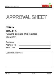
<strong>POE</strong>-<strong>D10</strong>-<strong>00</strong>-E-12SAFETY STANDARDS REGULATED, REINFORCEDINSULATION TYPE, AH SERIESVer: 12 Page: 7 / 184. Taping Format:Part number: □□0AH□□□□□□□□□AMD□B<strong>POE</strong> Part Number*BAMD0 / *DAMD0 / *XAMD0Item Symbol Dimensions(mm)Pitch of component P 25.4 ± 2Pitch of sprocket P0 12.7 ± 0.3Lead spacing F 10.0 ± 1.0Length from hole center to componentcenterP2 12.7 ± 1.5Length from hole center to lead P1 7.7 ± 1.5Body diameter D See the “3. Part numbering/T.C/Capacitance/ Tolerance/Diameter”Deviation along tape, life or right △ S0 ± 2.0Carrier tape width W 18.0 +1/ -0.5Position of sprocket hole W1 9.0 ± 0.5Lead distance between the kink and18.0 +2.0/-0H0center of sprocket hole(For: *DAMD0 & *XAMD0)Lead distance between the bottom of20.0+1.5/-1.0Hbody and the center of sprocket hole(For: *BAMD0)Protrusion length2.0max (Or the end of lead wire may be inside the tape.)Diameter of sprocket hole D0 4.0 ± 0.2Lead diameter φd 0.55 ±0.05Total tape thickness t1 0.6 ± 0.3Total thickness, tape and lead wire t2 1.5 max.Deviation across tape△ h12.0 max.△ h22.0 maxPortion to cut in case of defect L <strong>11</strong>.0 max.Hole-down tape width W0 8.0 minHole-down tape distortion W2 1.5 ± 1.5Coating extension on leads e 3.0 max for straight lead style; Not exceed the kink leads for kink lead.Body thickness T See the “3. Part numbering/T.C/Capacitance/ Tolerance/Diameter”