Chiller Units And air-water Heat pumps - Euroconfort
Chiller Units And air-water Heat pumps - Euroconfort
Chiller Units And air-water Heat pumps - Euroconfort

You also want an ePaper? Increase the reach of your titles
YUMPU automatically turns print PDFs into web optimized ePapers that Google loves.
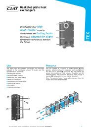
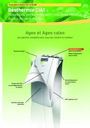
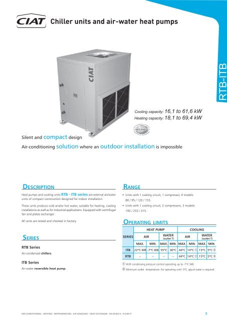
RTB-ITB<strong>Chiller</strong> units and <strong>air</strong>-<strong>water</strong> heat <strong>pumps</strong>Cooling capacity:<strong>Heat</strong>ing capacity:16,1 to 61,6 kW18,1 to 69,4 kWENVIRONMENTALLY FRIENDLYHFC R407CPROTECTION DE L'ENVIRONNEMENTSilent and compact designAir-conditioning solution where an outdoor installation is impossibleDESCRIPTION<strong>Heat</strong> <strong>pumps</strong> and cooling units RTB - ITB series are external <strong>air</strong>/<strong>water</strong>units of compact construction designed for indoor installation.These units produce cold and/or hot <strong>water</strong>, suitable for heating, coolinginstallations as well as for industrial applications. Equipped with centrifugalfan and plates exchanger.All units are tested and checked in factory.SERIESRTB SeriesAir-condensed chillers.ITB SeriesAir-<strong>water</strong> reversible heat pump.RANGE• <strong>Units</strong> with 1 cooling circuit, 1 compressor, 4 models:80 / 95 / 120 / 155.• <strong>Units</strong> with 1 cooling circuit, 2 compressors, 3 models:195 / 255 / 315.OPERATING LIMITSSERIESITBHEATAIRPUMPWATER(outlet T)AIRCOOLINGWATER( o utletT)M AX. M IN.M AX.M IN.M AX.M IN.M AX.MIN.22ºC WB-7ºCWB55ºC 0º C3 44ºC 14ºC➀ 15ºC 5ºC➁RTB--------44ºC 14ºC➀ 15ºC 5ºC➁➀ With condensing pressure control operating up to -7ºC WB.➁ Minimum outlet temperature. For operating until -5ºC, glycol <strong>water</strong> is required.AIR CONDITIONING - HEATING - REFRIGERATION - AIR HANDLING - HEAT EXCHANGE - NA 08.652 A - N 6405 P3
<strong>Chiller</strong> units and <strong>air</strong>-<strong>water</strong> heat <strong>pumps</strong>RTB-ITBDESIGNATIONseriesmodelexampleITB-95I = heat pumpR = coolingonly unitTB - <strong>air</strong>-<strong>water</strong> unitscentrifugal fanplates exchangerreversible heat pump<strong>air</strong> wate r-unitwith centrifugal fanmodelUNITS COMPOSITIONStandard equipment- Anticorrosion casing in galvanized metal plate covered with a polyesterand varnish lacquer. Chassis support.External circuit- Centrifugal fan(s) driven by motor or by belts and pulleys.- Coil with crimped aluminium fins and copper tubes.- Condensates drain pan.Internal circuit- Exchanger with stainless steel welded plates thermically isolated.Cooling circuit- Piston hermetic compressor with internal protection, mounted on antivibratorysupports, with gas discharge silencer.- Crankcase heater (ITB serie).- Thermostatic expansion valve, with external equalization.- Antiacid dryer filter.- Liquid vessel (ITB series).- Four ways reverse valve (ITB series).Protections- HP and LP pressostats.- Water flow control by differential pressostat in RTB - ITB model 80, andwith flow switch in RTB - ITB models 95 to 315.- Anti-frost protection, integrated in the control.- Main door switch.- Automatic circuit switch.- Motor fans and compressors circuits protection devices by circuit breakerfuse(s).- Fan thermal protection(s).Electrical panel- Complete electrical panel, totally wired.- General ground plug.- Compressor(s) and motor fan(s) contactor(s).Models 80 to 155:S55E1 electronic control (consult manual)Control system by microprocessor equipped with:Control board• Control of operating parameters and safeties management.• Failures diagnosis.• Anti-short-cycle timing.• Defrosting in reversible units.Electronic thermostat: AQUAGES 11N• Operating modes: cooling or heating.• Display on LCD screen of the functions and configuration of unitoperation in each moment.• Introduction of the set point and operation mode.• Memorization of operation parameters before lack of voltage.• Alarm display.Models 195 to 315:GESCLIMA+ electronic control (consult manual)Control system by microprocessor equipped with:Control board• Control of operating parameters and safeties management.• Temperature probe for defrosting operation.• Anti-short-cyle timing.• Self-adapting control of compressor operating time, reducing thenumber of start-ups of the compressor and therefore reducing thepower consumption and increasing the life span of components. Italso allows to reduce the buffer tank size.• Set point offset depending on external temperature.• Possibility of communication with a building management systemBMS with Modbus protocol.Electronic thermostat: DOMO• Operating modes: cooling or heating.• Operating parameters modification (set points, differential andtimings).• Time and daily scheduling. Night reduction mode.• Alarm display by codes.Options- Coil of copper tubes and aluminium fins with polyurethane coating.- Options for control and controls.- Compressor acoustic isolation.- Condensing pressure control.- Air filter.- Flexible hydraulic connections.- Rubber anti-vibratory supports.4AIR CONDITIONING - HEATING - REFRIGERATION - AIR HANDLING - HEAT EXCHANGE - NA 08.652 A - N 6405 P
MAXIMUM CURRENTS (A)<strong>Chiller</strong> units and <strong>air</strong>-<strong>water</strong> heat <strong>pumps</strong>RTB-ITBRTB- ITB SERIES8095120155195255315COMPRESSOREXTERNAL FANTOTAL230V / III ph / 50 Hz293543512x352x432x51400V / III ph / 50 Hz232227362x222x272x36230V / III ph / 50 Hz4,7 6,1 8,7 11,9 2x6,1 2x8,7 2x11,9400V / III ph / 50 Hz2,7 3,65 6,9 2x3,6 2x5 2x 6, 9230V / III ph / 50 Hz33,7 41,1 51,7 62,9 82,2 103,4 125, 8400V / III ph / 50 Hz25,7 25,6 3242,9 51,2 6485, 8ELECTRICAL WIRING1 2THE CONNECTIONS TO EXECUTE ARE THE FOLLOWING ONES:NºDESCRIPTION80951201551952553151 POWER SUPPLY230V / III ph / 50 Hz (±5%)400V / III ph / 50 Hz (±5%)3 + GND3 + N + GND2 THERMOSTATCONNECTION22 x 1 mmNOTE: If the unit is going to be installed in an industrial ambient with high level of EMC interferences, it is recommended to shield the wires of the controlthermostat.NOTE: In 195 / 255 / 315 models the cooling/heating control is of two stages.NOTE: The installer should plan two wires of 0,75 mm 2 in order to install an ON/OFF switch external to the unit. In ITB units, it is also necessary to providethree wires of 0,75 mm 2 in order to install a cooling/heating switcher.CONTROLRTB- ITB SERIES80 95120155195255315COOLING CONTROL (ITB / RTB)HEATING CONTROL(ITB)ANTIFROSTSAFETY (ITB / RTB)12º C12 - 13 º C45º C45 - 44 º C3 º C3 º CNOTE: Manufactured control: it is necessary to verify the <strong>water</strong> flow checking that the inlet and <strong>water</strong> outlet temperatures are between the operating limits.Other control values are allowed once verified that the flow and the temperatures are within the operating limits.6AIR CONDITIONING - HEATING - REFRIGERATION - AIR HANDLING - HEAT EXCHANGE - NA 08.652 A - N 6405 P
<strong>Chiller</strong> units and <strong>air</strong>-<strong>water</strong> heat <strong>pumps</strong>SOUND LEVEL GIVEN FOR 10 MMWG AVAILABLE PRESSUREGlobal sound pressure level at 5 meters from the unit, at 1.5 meters from the ground, in free field, directivity 2, with inlet and outlet connectedto the duct:RTB- ITB8095120155195255315dB(A)50505454565757Global sound power level at the inlet (values to be taken into account for the calculatións of the silencers):RTB- ITB8095120155195255315dB(A)74,476,381,383,1 79,384,386, 1RTB-ITBGlobal sound power level at the outlet (values to be taken into account for the calculatións of the silencers):RTB- ITB8095120155195255315dB(A)82828484848490When planning the installation,take into consideration the location (residential area, housings, industrial area...) and if the radiated noise from theunit is higher than the noise estimated for the installation:• An acoustic study.• An appropriate acoustic treatment if necessary.• Implementation precautions.COOLING CAPACITY (kW)<strong>Units</strong> 1 compressor / 1 stage / 1 circuitRTBITBChilled <strong>water</strong> outlettemperature in ºCPfEXTERNAL AIRTEMPERATURE29 ºC 32 º C 35 º C 38 º C 40 º C 44 º CPaPfPaPfPaPfPaPfPaPfPa-411,005,5010,605,6010,205,759,805,959,606,059,106,20Glycol <strong>water</strong>-212,105,7011,705,8011,305,9010,806,1010,606,2510,106,400 13,105,9012,706,0012,306,1011,906,2011,606,4511,106,602 14,206,1013,806,2013,406,3012,906,3512,606,6012,106,80805 15,806,4015,406,5015,006,6014,506,8014,207,0013,607,206 16,406,5015,906,6015,506,7015,006,9014,707,1014,107,30Pure <strong>water</strong>7 16,906,6016,506,7016,106,8015,607,0015,207,2014,607,408 17,506,7017,006,8016,606,9016,107,1015,807,3015,107,501018,706,8018,206,9017,807,0017,207,2516,807,5016,107,701219,906,9019,407,0018,907,2018,107,4517,907,7017,107,80Pf: Cooling capacity in KWPa: Power input by the compressor.These values can be interpolated, but never extrapolatedAIR CONDITIONING - HEATING - REFRIGERATION - AIR HANDLING - HEAT EXCHANGE - NA 08.652 A - N 6405 P7
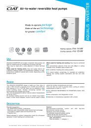
<strong>Chiller</strong> units and <strong>air</strong>-<strong>water</strong> heat <strong>pumps</strong>DIMENSIONS SCHEMESRTB / ITB / 80 / 95 HORIZONTAL DISCHARGERTB-ITBH I JBPOC1NR2MQFKLG500mmSCondensatesdrainingGas thread M 3/4"E500mm500mmKeep this space freefor installation andmaintenanceDA1500mmMODELA B C D E F G H I J K L M N O P Q R S80/ 951.1748281.22747,5 710291.11644415,5 475161,5 850139476152408244520102, 5LEGEND:AIR FLOWPOWER SUPPLY AND ELECTRICAL PANEL1WATER INLET2WATER OUTLETNote: All models have 4 drills (18 mm diameter)for antivibratory - supports12AIR CONDITIONING - HEATING - REFRIGERATION - AIR HANDLING - HEAT EXCHANGE - NA 08.652 A - N 6405 P
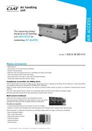
<strong>Chiller</strong> units and <strong>air</strong>-<strong>water</strong> heat <strong>pumps</strong>RTB / ITB - 120 / 155 HORIZONTAL DISCHARGEH I JBPONCR12RTB-ITBMQ500mmKLF500mmGSCondensatesdrainingGas thr ead M3/4"E500mmKeep this space free forinstallation and maintenanceDA1500mmMODELA B C D E F G H I J K L M N O P Q R S120/ 1551.4408771.31247,5 7591.3822944117,5 1.117161,5 1.11713879062294200520102, 5LEGEND:AIR FLOWPOWER SUPPLY AND ELECTRICAL PANEL1WATER INLET2WATER OUTLETNote: All models have 4 drills (18 mm diameter)for antivibratory - supportsAIR CONDITIONING - HEATING - REFRIGERATION - AIR HANDLING - HEAT EXCHANGE - NA 08.652 A - N 6405 P13
<strong>Chiller</strong> units and <strong>air</strong>-<strong>water</strong> heat <strong>pumps</strong>RTB / ITB - 195 HORIZONTAL DISCHARGERTB-ITBH I J KBQPOCS12NRLMTCondensatesdrainingGas thread M3/4"FG750mm1000mmE1000mmDA1500mmKeep this space free for installation and maintenanceMODELA B C D E F G H I J K L M N O P Q R S T1952.161837,5 1.22747,5 710292.10344415,5 475292161,5 1.838139506122408244526102, 5LEGEND:AIR FLOWPOWER SUPPLY AND ELECTRICAL PANEL1WATER INLET2WATER OUTLETNote: All models have 4 drills (18 mm diameter)for antivibratory - supports14AIR CONDITIONING - HEATING - REFRIGERATION - AIR HANDLING - HEAT EXCHANGE - NA 08.652 A - N 6405 P
<strong>Chiller</strong> units and <strong>air</strong>-<strong>water</strong> heat <strong>pumps</strong>RTB / ITB - 255 / 315 HORIZONTAL DISCHARGEH I J KBLMQPONCSRT12CondensatesdrainingGas thread M3/4"RTB-ITBFG750mm1000mmE1000mmDA1500mmKeep this space free for installation and maintenanceMODELA B C D E F G H I J K L M N O P Q R S T255/ 3152.7048801.31247,5 759292.64644117,5 1.117147161,5 2.38113879062294200520102, 5LEGEND:AIR FLOWPOWER SUPPLY AND ELECTRICAL PANEL1WATER INLET2WATER OUTLETNote: All models have 4 drills (18 mm diameter)for antivibratory - supportsAIR CONDITIONING - HEATING - REFRIGERATION - AIR HANDLING - HEAT EXCHANGE - NA 08.652 A - N 6405 P15
<strong>Chiller</strong> units and <strong>air</strong>-<strong>water</strong> heat <strong>pumps</strong>RTB / ITB - 80 / 95 / 120 / 155 VERTICAL DISCHARGE (OPTIONAL)RTB-ITBH I JOPNCR12MQ500mmKLF500mmGSBCondensatesdrainingGas thread M 3/4"E500mmKeep this space free forinstallation and maintenanceDA500mmMODELA B C D E F G H I J K L M N O P Q R S80/ 951.1748281.22747,5 7101.1162944415,5 475161,5 850139476259,5 408244520102, 5120/ 1551.4408771.31247,5 7591.3822944437,5 477161,5 1.11713879091408200520102, 5LEGEND:AIR FLOWPOWER SUPPLY AND ELECTRICAL PANEL1WATER INLET2WATER OUTLETNote: All models have 4 drills (18 mm diameter)for antivibratory - supports16AIR CONDITIONING - HEATING - REFRIGERATION - AIR HANDLING - HEAT EXCHANGE - NA 08.652 A - N 6405 P
<strong>Chiller</strong> units and <strong>air</strong>-<strong>water</strong> heat <strong>pumps</strong>RTB / ITB - 195 / 255 / 315 VERTICAL DISCHARGE (OPTIONAL)H I J KPQOCS12RTB-ITBNRLMTBFG750mmCondensatesdrainingGas thread M3/4"1000mmE1000mmDA500mmKeep this space free for installation and maintenanceMODELA B C D E F G H I J K L M N O P Q R S T1952.161837,5 1.22747,5 710292.10344415,5 475292161,5 1838139506135408246526102, 5255/ 3152.7048801.31247,5 759292.64644434,5 475796161,5 2.38113879091408200520102, 5LEGEND:AIR FLOWPOWER SUPPLY AND ELECTRICAL PANEL1WATER INLET2WATER OUTLETNote: All models have 4 drills (18 mm diameter)for antivibratory - supportsAIR CONDITIONING - HEATING - REFRIGERATION - AIR HANDLING - HEAT EXCHANGE - NA 08.652 A - N 6405 P17
<strong>Chiller</strong> units and <strong>air</strong>-<strong>water</strong> heat <strong>pumps</strong>MAXIMUM SERVICE PRESSURE (Bar)RTB-ITBRTB- ITBSERIESCOOLING CIRCUITHYDRAULIC CIRCUITWATER EXCHANGER2910AIR COIL29--OPERATION WITH GLYCOL WATERCORRECTION COEFFICIENTSPOSITIVE RATENEGATIVE RATECooling capacityE10,98According to capacities tableEVAPORATORChilled<strong>water</strong> flowE21,051, 1Waterpressure dropE31,151, 3Medium rateº C12/ 7See graphic<strong>Heat</strong>ing capacityE10,97--CONDENSERHot<strong>water</strong> flowE21,05--Waterpressure dropE31,10--Medium rateº C35/ 40--Anti-frost protection with glycol <strong>water</strong>: Freezing pointC oncentration % 0 10203040Etylen-glicolPropylen-glicolº C0 -3,8-8,3-14,5-23, 3º C0 -2,7-6,5-11,4-20, 0OPERATING LIMITS∆T. (allowance difference <strong>water</strong> I/O in ºC)987654321-5 -2 0 2 4 6 8 10 12 14Water outlet T. in ºCMax. ∆TMin. ∆TFor a <strong>water</strong> outlet T of +5ºC:∆T minimum: 3,1ºC Water T rate: 8,1ºC / 5ºC∆T maximum: 6,2ºC Water T rate: 11,2ºC / 5ºCFor T differences not included between the curves: consult.18AIR CONDITIONING - HEATING - REFRIGERATION - AIR HANDLING - HEAT EXCHANGE - NA 08.652 A - N 6405 P