Air-to-water reversible heat pumps - Euroconfort
Air-to-water reversible heat pumps - Euroconfort
Air-to-water reversible heat pumps - Euroconfort
- No tags were found...

You also want an ePaper? Increase the reach of your titles
YUMPU automatically turns print PDFs into web optimized ePapers that Google loves.
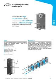
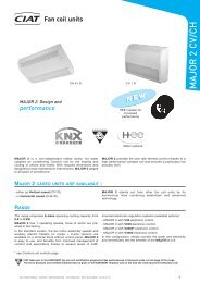
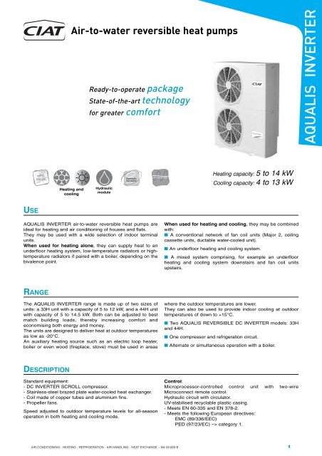
<strong>Air</strong>-<strong>to</strong>-<strong>water</strong> <strong>reversible</strong> <strong>heat</strong> <strong>pumps</strong>Ready-<strong>to</strong>-operate packageState-of-the-art technologyfor greater comfortAQUALIS INVERTERHFCR410AHeating andcoolingHydraulicmoduleHeating capacity: 5 <strong>to</strong> 14 kWCooling capacity: 4 <strong>to</strong> 13 kWUSEAQUALIS INVERTER air-<strong>to</strong>-<strong>water</strong> <strong>reversible</strong> <strong>heat</strong> <strong>pumps</strong> areideal for <strong>heat</strong>ing and air conditioning of houses and flats.They may be used with a wide selection of indoor terminalunits.When used for <strong>heat</strong>ing alone, they can supply <strong>heat</strong> <strong>to</strong> anunderfloor <strong>heat</strong>ing system, low-temperature radia<strong>to</strong>rs or hightemperatureradia<strong>to</strong>rs if paired with a boiler, depending on thebivalence point.When used for <strong>heat</strong>ing and cooling, they may be combinedwith:■ A conventional network of fan coil units (Major 2, ceilingcassette units, ductable <strong>water</strong>-cooled unit).■ An underfloor <strong>heat</strong>ing and cooling system.■ A mixed system comprising, for example an underfloor<strong>heat</strong>ing and cooling system downstairs and fan coil unitsupstairs.RANGEThe AQUALIS INVERTER range is made up of two sizes ofunits: a 33H unit with a capacity of 5 <strong>to</strong> 12 kW, and a 44H unitwith capacity of 5 <strong>to</strong> 14.5 kW. Both can be adjusted <strong>to</strong> bestmatch building loads, thereby increasing comfort andeconomising both energy and money.The units are designed <strong>to</strong> deliver <strong>heat</strong> at outdoor temperaturesas low as -20°C.An auxiliary <strong>heat</strong>ing source such as an electric loop <strong>heat</strong>er,boiler or even wood (fireplace, s<strong>to</strong>ve) must be used in areaswhere the outdoor temperatures are lower.They can also be used <strong>to</strong> provide indoor cooling at outdoortemperatures of down <strong>to</strong> +15°C.■ Two AQUALIS REVERSIBLE DC INVERTER models: 33Hand 44H.■ One compressor and refrigeration circuit.■ Alternate or simultaneous operation with a boiler.DESCRIPTIONStandard equipment:- DC INVERTER SCROLL compressor.- Stainless-steel brazed plate <strong>water</strong>-cooled <strong>heat</strong> exchanger.- Coil made of copper tubes and aluminium fins.- Propeller fans.Speed adjusted <strong>to</strong> outdoor temperature levels for all-seasonoperation in both <strong>heat</strong>ing and cooling mode.Control:Microprocessor-controlled control unit with two-wireMicroconnect remote control.Hydraulic circuit with circula<strong>to</strong>r.UV-stabilised recyclable plastic casing.- Meets EN 60-335 and EN 378-2.- Meets the following European directives:EMC (89/336/EEC)PED (97/23/EC) –> category 1.AIR CONDITIONING - HEATING - REFRIGERATION - AIR HANDLING - HEAT EXCHANGE – NA 09.669 B1
QUICK SELECTION<strong>Air</strong>-<strong>to</strong>-<strong>water</strong> <strong>reversible</strong> <strong>heat</strong> <strong>pumps</strong>AQUALIS INVERTERAQUALIS INVERTER33H44HMinimum Nominal Maximum Minimum Nominal MaximumHeating capacity +7°C 5.3 10.2 11.9 5.3 12.2 14.535°CCOP 3.79 4 3.72 3.53 3.81 3.92Heating capacity -7°C 3.5 6.6 10.5 3.3 7.3 11.4COP 2.7 2.68 2.28 2.36 2.32 2.11Heating capacity +7°C 4.9 9.9 10.2 5.1 11.4 12.445°CCOP 3.07 3.14 2.68 3 3.04 2.76Heating capacity -7°C 3.3 6.3 10.3 3.1 7.2 10.6COP 2.1 2.1 1.87 1.83 2.03 1.63Heating capacity +7°C 4.7 9.3 10.54 4.8 10.7 12.655°CCOP 2.47 2.48 2.33 2.4 2.35 2.38Heating capacity -7°C 3.1 6.4 9 2.9 6.5 9.3COP 1.72 1.94 1.3 1.53 1.76 1.13Energy rating A BSupply voltage230 V - 1 - 50 HzSound level dB(A) (1) 37 46 47 37 48 49(1) 5 m from unit, 1.5 m from floor, directivity 2 ± 3 dBA at 10°CCOMPOSITIONHermetic compressor- DC INVERTER rotary scroll compressor. Two scrolls (onefixed and one orbiting).- Built-in electric mo<strong>to</strong>r cooled by suction gas.- Mo<strong>to</strong>r protected by internal winding sensor.- Noise insulation.Water-<strong>to</strong>-refrigerant <strong>heat</strong> exchangers- Brazed plates.- AISI 316 stainless steel intermediate and end plates.- High-performance, optimised plate patterns.- Thermal insulation.<strong>Air</strong>-cooled <strong>heat</strong> exchanger- Bent coil, copper tubes and aluminium fins.Standard components- Reversing valve.- Suction accumula<strong>to</strong>r.- Liquid tank.- Electronic expansion valve.- Dryer.- Crankcase <strong>heat</strong>er.Electrical panel- Box conforms <strong>to</strong> EN 60335 standard.- Main earth connection.- Electronic control unit with microprocessor:· Uses a <strong>water</strong> law <strong>to</strong> adjust the hot <strong>water</strong> or chilled <strong>water</strong>temperature based on the outdoor temperature.· Boiler backup mode: au<strong>to</strong>matically runs the <strong>heat</strong> pump andboiler, either alternately or simultaneously, using a setting thatcan be adjusted based on the outdoor temperature.· Moni<strong>to</strong>rs the operating and safety settings.· Displays the temperatures on the terminal.· <strong>Air</strong> setpoints in comfort unit and RFHC mode.· Controls the unit.· Two-wire remote-control terminal. ON/OFF input control (twoinputs, au<strong>to</strong>matic/load shedding, <strong>heat</strong>ing - cooling/absence).- 5-minute short-cycle protection.- Optimised defrosting.Control and safety unit- High-pressure safety switch.- Pressure sensors (HP/LP).- Two frost sensors (exchanger <strong>water</strong> outlet and exchangerrefrigerant outlet).- Water sensors on exchanger <strong>water</strong> inlet and outlet.- Coil sensor.- Outdoor sensor.- Suction sensor.Built-in hydraulic module- Safety valve set at 4 bar.- Manual air bleed valve.- Multispeed circula<strong>to</strong>r.- Differential <strong>water</strong> pressure switch.Accessories (option) (for installation on site)- Insulated hose assemblies.- Anti-vibration mounts.- Screen filter with ball valve kit.- Filling kit.- Loop <strong>heat</strong>er.2AIR CONDITIONING - HEATING - REFRIGERATION - AIR HANDLING - HEAT EXCHANGE – NA 09.669 B
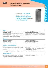
<strong>Air</strong>-<strong>to</strong>-<strong>water</strong> <strong>reversible</strong> <strong>heat</strong> <strong>pumps</strong>HYDRAULIC MODULE PRINCIPLE DIAGRAM-+46OUTINAQUALIS INVERTER1 Brazed-plate <strong>heat</strong> exchanger2 Au<strong>to</strong>matic air bleed valve3 Circula<strong>to</strong>r4 Differential pressure switch5 Temperature sensors6 Screen filter (accessories)OPERATING LIMITSChilled <strong>water</strong> productionMaximum <strong>water</strong> return temperature during operation: +40°CHot <strong>water</strong> productionMinimum <strong>water</strong> return temperature for warm-up:Frost protection fluid: +5°C / Pure <strong>water</strong>: +10°CMaximum <strong>water</strong> inlet temperature: +70°C60Water outlet temperature (°C)PURE WATERMix ofPURE WATER + FROSTPROTECTION FLUID(Example: 40% MPG)Initial <strong>water</strong> temperature (°C)54Mix ofPUREWATER +FROSTPROTECTIONFLUID(Example:40% MPG)PURE WATER-105Outdoor air temperature in °C (DB)Outdoor air temperature in °C (DB)Required <strong>water</strong> flow rateAQUALIS INVERTER 33H 44HMinimum flow rate (m 3 /h) 1.4 1.4Nominal flow rate, cooling mode (m 3 /h) 2.1 2.4Nominal flow rate, <strong>heat</strong>ing mode (m 3 /h) 1.8 2.1AIR CONDITIONING - HEATING - REFRIGERATION - AIR HANDLING - HEAT EXCHANGE – NA 09.669 B3
HEATING CAPACITIES<strong>Air</strong>-<strong>to</strong>-<strong>water</strong> <strong>reversible</strong> <strong>heat</strong> <strong>pumps</strong>AQUALIS INVERTERAqualisInverterOutdoor airtemp.°CPinomHcnomunderfloor <strong>heat</strong>ing system fan coil unit radia<strong>to</strong>r cast iron radia<strong>to</strong>r25°C 35°C 45 °C 55 °C 60 °CPimaxHcmaxPinomHcnomPimaxHcmaxPinomHcnomkW kW kW kW kW kW kW kW kW kW kW kW kW kW kW kW kW kW kW kW-20 2.0 4.6 2.0 4.6 2.3 4.5 2.3 4.5 2.9 4.4 2.9 4.4 - - - - - - - --15 2.0 5.3 3.1 8.0 2.3 5.3 3.8 7.8 3.0 5.2 4.6 7.6 3.0 5.0 4.1 7.6 - - - --10 2.0 6.3 3.6 10.1 2.4 6.1 4.5 10.0 3.0 5.9 5.4 9.8 3.2 5.3 4.2 8.3 3.3 6.2 4.5 7.8-5 2.1 7.2 3.7 11.1 2.5 6.9 4.7 11.3 3.0 6.7 5.6 10.8 3.2 6.0 4.3 8.6 3.7 6.8 4.7 9.1PimaxHcmaxPinomHcnomPimaxHcmaxPinomHcnomPimaxHcmax33H0 2.1 8.0 3.7 11.5 2.5 7.8 4.8 11.8 3.0 7.6 5.7 11.2 3.6 7.4 4.4 9.3 3.9 7.3 4.7 9.35 2.1 9.4 2.7 11.9 2.5 9.2 3.1 11.4 3.1 9.0 3.7 10.5 3.7 8.3 4.4 10.1 4.1 8.3 4.7 9.910 2.1 11.1 2.7 13.5 2.6 10.9 3.2 13.2 3.2 10.6 3.8 12.2 3.8 9.8 4.5 11.5 4.1 9.5 4.9 11.315 2.1 12.5 2.7 15.5 2.6 12.2 3.2 15.0 3.2 11.8 3.9 14.0 3.9 11.0 4.6 13.0 4.2 10.5 4.9 12.520 2.1 14.4 2.8 17.5 2.7 13.5 3.3 16.5 3.3 12.9 4.0 15.9 3.9 12.1 4.6 14.4 4.3 11.6 5.0 13.8-20 2.4 5.1 2.4 5.1 2.9 5.1 2.9 5.1 3.0 5.0 3.0 5.0 - - - - - - - --15 2.4 5.9 3.9 9.7 2.9 5.9 4.6 8.8 3.5 5.8 5.4 9.3 3.5 6.0 4.9 9.0 - - - --10 2.5 7.2 4.1 10.5 3.1 6.8 5.3 10.4 3.5 6.7 6.1 10.3 3.7 6.3 5.0 9.6 3.4 6.6 5.5 9.1-5 2.6 8.1 4.4 12.1 3.2 7.9 5.4 12.0 3.6 7.6 6.5 11.6 3.7 6.8 5.1 10.0 3.8 7.6 5.5 9.944H0 2.6 9.4 4.4 13.2 3.2 8.7 5.5 12.8 3.7 8.5 6.6 11.8 3.8 8.0 5.2 10.6 4.1 8.5 5.6 10.55 2.6 11.0 4.4 14.0 3.2 11.0 3.6 13.0 3.7 10.2 4.4 11.9 4.5 9.5 5.2 11.4 4.9 9.8 5.7 11.110 2.6 13.0 4.4 16.9 3.2 12.8 3.7 15.0 3.8 12.2 4.5 14.0 4.6 11.4 5.4 13.0 4.9 10.8 5.9 12.615 2.6 15.1 4.5 19.0 3.2 14.7 3.7 17.1 3.8 13.6 4.6 16.1 4.7 12.8 5.5 15.1 5.0 12.2 6.0 14.720 2.7 17.3 4.5 21.1 3.3 16.6 3.8 19.1 4.0 15.5 4.7 18.5 4.8 14.4 5.5 17.0 5.2 13.6 6.1 16.1COOLING CAPACITIES<strong>water</strong>AqualisoutletInvertertemp.33H44HCcnom20°C 25°C 30°C 35°C 40°C 43°CPinomCcmaxPimaxCcnomPinomCcmaxPimaxCcnomPinomCcmaxPimaxkW kW kW kW kW kW kW kW kW kW kW kW kW kW kW kW kW kW kW kW kW kW kW kW5 9.6 2.3 11.1 2.7 9.3 2.5 10.8 3.0 9.0 2.7 10.2 3.3 8.4 3.0 9.6 3.5 7.9 3.2 8.9 3.9 7.5 3.4 8.5 4.07 10.3 2.3 11.8 2.8 10.0 2.5 11.4 3.0 9.5 2.8 10.9 3.3 9.0 3.0 10.3 3.6 8.5 3.3 9.5 3.9 8.0 3.4 9.0 4.110 11.1 2.3 12.9 2.8 10.9 2.6 12.4 3.1 10.4 2.8 11.9 3.4 9.8 3.1 11.2 3.7 9.1 3.3 10.4 4.0 8.7 3.5 9.9 4.215 13.0 2.4 14.9 2.9 12.5 2.6 14.5 3.2 12.0 2.9 13.7 3.5 11.3 3.1 12.9 3.8 10.6 3.4 12.0 4.1 10.1 3.6 11.4 4.318 14.1 2.4 16.2 2.9 13.7 2.7 15.6 3.2 13.1 2.9 14.8 3.6 12.3 3.2 13.9 3.9 11.5 3.5 12.9 4.2 10.9 3.6 12.3 4.420 14.9 2.4 17.2 3.0 14.5 2.7 16.5 3.3 13.9 3.0 15.6 3.6 13.1 3.2 14.6 3.9 12.1 3.5 13.6 4.3 11.5 3.7 13.0 4.45 10.7 2.9 12.2 3.3 10.6 3.1 11.9 3.7 10.1 3.4 11.3 4.0 9.4 3.7 10.6 4.4 8.8 4.0 9.8 4.7 8.4 4.2 9.3 4.97 11.5 2.9 12.9 3.4 11.1 3.2 12.5 3.7 10.6 3.5 11.9 4.1 10.1 3.8 11.3 4.4 9.4 4.1 10.5 4.8 9.0 4.3 10.0 5.010 12.5 2.9 14.2 3.4 12.3 3.2 13.7 3.8 11.7 3.5 13.1 4.1 11.0 3.8 12.3 4.5 10.3 4.2 11.5 4.9 9.8 4.4 10.9 5.115 14.6 3.0 16.5 3.5 14.2 3.3 15.8 3.9 13.5 3.6 15.0 4.3 12.7 4.0 14.2 4.7 11.9 4.3 13.2 5.0 11.4 4.5 12.5 5.318 16.0 3.0 17.9 3.6 15.5 3.3 17.2 4.0 14.8 3.7 16.4 4.4 13.9 4.0 15.3 4.7 13.0 4.4 14.3 5.1 12.3 4.6 13.6 5.420 16.9 3.1 18.9 3.6 16.3 3.4 18.2 4.0 15.5 3.7 17.3 4.4 14.6 4.0 16.2 4.8 13.6 4.4 15.0 5.2 13.0 4.6 14.4 5.5CcnomPinomCcmaxPimaxCcnomPinomCcmaxPimaxCcnomPinomCcmaxPimaxPi = Power input for compressor + control + fan(s)Hc = Heating capacityCc = Cooling capacityPower consumption level calculations include defrosting cycles4AIR CONDITIONING - HEATING - REFRIGERATION - AIR HANDLING - HEAT EXCHANGE – NA 09.669 B
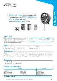
PUMP SPECIFICATIONSAvailable pressure in systemAQUALIS INVERTER 33H - 44HAvailable static pressure (kPa)70,060,050,040,030,0<strong>Air</strong>-<strong>to</strong>-<strong>water</strong> <strong>reversible</strong> <strong>heat</strong> <strong>pumps</strong>V3V2V3V2V1AQUALIS INVERTER20,010,00,0V11 1,5 2 2,5 3 3,5 4Qv m 3 /hThe available pressure curves are given for pure <strong>water</strong>.Subtract 5 kPa from the available pressures in the case of systems using 40% monopropylene glycol (<strong>heat</strong>ing mode).DIMENSIONSREAR VIEWOverallDETAIL AElectrical channelabOPTIONALAnti-vibration mountsOverall1 1 ¼4” G male <strong>water</strong> connectionsa = outletb = inlet25 mm condensatetube4 mounting points (M8 screws)AIR CONDITIONING - HEATING - REFRIGERATION - AIR HANDLING - HEAT EXCHANGE – NA 09.669 B5
<strong>Air</strong>-<strong>to</strong>-<strong>water</strong> <strong>reversible</strong> <strong>heat</strong> <strong>pumps</strong>TECHNICAL CHARACTERISTICSAQUALIS INVERTERAQUALIS INVERTER 33H 44HQuantity 1TypeDC INVERTER SCROLLCompressor1.7Oil capacityLPOE oil (MEL 56)Crankcase <strong>heat</strong>er W 45RefrigerantR410ARefrigerant weight kg 2.99Coil typeGrooved copper tubes with aluminium finsWater-cooled HEX Water capacity L 1.6TypePropellerFanQuantity 2Speed rpm 640/400 700/450Circula<strong>to</strong>r3 speedsMaximum service pressure bar 4Maximum system capacity: pure <strong>water</strong> /Hydraulic module40% glycol solutionL 330/190with 5 l expansion vessel (not supplied)*Minimum pure <strong>water</strong> capacity of system forsmooth running of your unitL 80WeightEmpty kg 144In operation kg 147* A higher capacity expansion vessel is needed for larger volumesSOUND LEVELS*AQUALIS INVERTER 33H 44HSound pressure levels dB (A) 37 <strong>to</strong> 47 37 <strong>to</strong> 49* 5 metres from unit, 1.5 metres from ground, in a free field, directivity 2ELECTRICAL CHARACTERISTICSAQUALIS INVERTER 33H 44HRated voltage of unit230 V - 1-ph+N+Earth - 50 HzCompressor maximum operating current A 30.5 31Fans maximum operating current A 0.47 x 2 0.74 x 2Circula<strong>to</strong>runit power min115Wunit power max 210rated currentmin0.6Arated current max 1Max. current of entire unit A 33 34Starting current A < 5Electrical wiring not supplied (1) mm² 3G10C or D curve circuit breaker (not supplied) Am 40Thermostat, pool sensor, On/Off input connections mm² 0.2 - 1Control circuit connection kit mm² 1(1) PVC cable for temperatures below 45°C and a maximum length of 30 m.Note: for other conditions, refer <strong>to</strong> French standard NF C 15-100 or the relevant prevailing standard in the country of installation.6AIR CONDITIONING - HEATING - REFRIGERATION - AIR HANDLING - HEAT EXCHANGE – NA 09.669 B
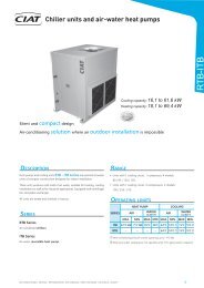
<strong>Air</strong>-<strong>to</strong>-<strong>water</strong> <strong>reversible</strong> <strong>heat</strong> <strong>pumps</strong>SCHEMATIC INSTALLATION DIAGRAMResidential comfort units and/or underfloor <strong>heat</strong>ing and cooling systemOutdoor sensorMAJOR 2 MAJOR 2CONTROLLERRoom sensorUnderfloor systemAQUALIS INVERTERDUO hydraulic module(option)Circuitbreaker+gaugePool <strong>heat</strong>ing(option)FillingkitSafetyvalveIntermediate<strong>heat</strong> exchangerPWAPool filter unitHeater(option)Buffer tankScreen filterInsulated flexibleconnectionsCu<strong>to</strong>ff valvesThermometer portsControl valvesNote: The schematic diagrams herein are provided for information only. Under no circumstances do they constitute actualinstallation diagrams.AIR CONDITIONING - HEATING - REFRIGERATION - AIR HANDLING - HEAT EXCHANGE – NA 09.669 B7
INSTALLATION ADVICELocation<strong>Air</strong>-<strong>to</strong>-<strong>water</strong> <strong>reversible</strong> <strong>heat</strong> <strong>pumps</strong>AQUALIS INVERTER units are designed <strong>to</strong> be installedoutdoors on a home deck/patio or in a garden.■ Nothing should obstruct the air flow over the coil or the fandischarge.■ Carefully consider where <strong>to</strong> install the unit and choose alocation appropriate for the surrounding environment (soundlevels, integration on site, etc.).■ Sufficient clearance should be left around the unit <strong>to</strong> allowfor connections, servicing and maintenance.Electrical connectionsAll the information needed <strong>to</strong> wire the system is provided onthe wiring diagram supplied with the unit. The diagram shouldbe followed <strong>to</strong> the letter.Wiring must be carried out in accordance with acceptedengineering practice and conform <strong>to</strong> the regulations in force.A cut-off switch and circuit breaker must be installed on theconsumer unit by the fitter.NOTE: To protect the unit from freezing temperatures, leave i<strong>to</strong>n <strong>to</strong> allow the <strong>water</strong> <strong>to</strong> continue flowing through the <strong>water</strong>circuit. Add glycol if the outdoor temperature falls below 0°C.Hydraulic connectionsHydraulic connections are <strong>to</strong> be made in accordance with goodengineering practice.To prevent transmitting noise through the ground or pipes, werecommend using flexible hydraulic connections and placinganti-vibration mounts under the unit.■ Install a screen filter with a maximum particle size of nomore than 600 µm on the <strong>water</strong> circuit <strong>to</strong> protect the plateexchanger from fouling.Commissioning■ Follow the instructions given in our installation andmaintenance manuals.Maintenance■ Follow the owner’s manual.■ Take out a maintenance contract.AQUALIS INVERTERClearance <strong>to</strong> be left around the unit (MM)300300This document is non-contractual.As part of its policy of continual product improvement, CIAT reserves the right <strong>to</strong> make any technical modification it feels appropriate without prior notification.Head officeAvenue Jean Falconnier - B.P. 1401350 - Culoz - FranceTel.: +33 (0)4 79 42 42 42Fax: +33 (0)4 79 42 42 10info@ciat.fr - www.ciat.comCIAT ServiceTel.: +33 (0)4 79 42 42 90Fax: +33 (0)4 79 42 42 13Compagnie Industrielle d’Applications Thermiques - S.A. with a registered capital of 26 728 480 € - R.C.S. Bourg-en-Bresse B 545 620 114