AIR COMP ACT AIR COMP ACT - Euroconfort
AIR COMP ACT AIR COMP ACT - Euroconfort
AIR COMP ACT AIR COMP ACT - Euroconfort

Create successful ePaper yourself
Turn your PDF publications into a flip-book with our unique Google optimized e-Paper software.
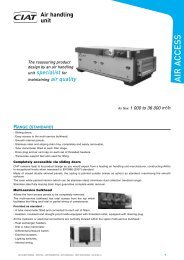
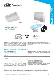
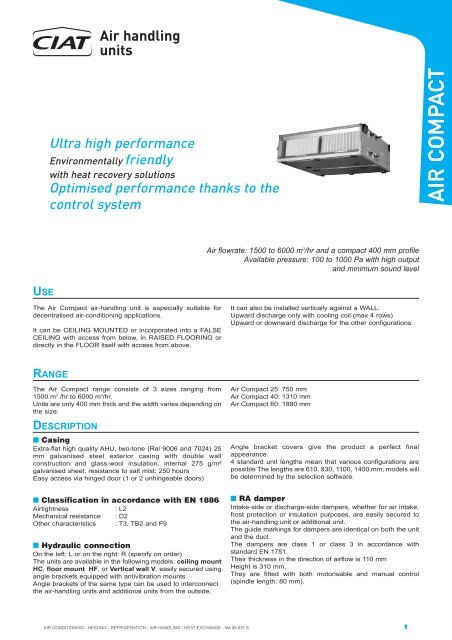
Air handling<br />
units<br />
Ultra high performance<br />
Environmentally friendly<br />
with heat recovery solutions<br />
Optimised performance thanks to the<br />
control system<br />
<strong>AIR</strong> <strong>COMP</strong><strong>ACT</strong><br />
Air flowrate: 1500 to 6000 m 3 /hr and a compact 400 mm profile<br />
Available pressure: 100 to 1000 Pa with high output<br />
and minimum sound level<br />
USE<br />
The Air Compact air-handling unit is especially suitable for<br />
decentralised air-conditioning applications.<br />
It can be CEILING MOUNTED or incorporated into a FALSE<br />
CEILING with access from below, in RAISED FLOORING or<br />
directly in the FLOOR itself with access from above.<br />
It can also be installed vertically against a WALL:<br />
Upward discharge only with cooling coil (max 4 rows)<br />
Upward or downward discharge for the other configurations.<br />
RANGE<br />
The Air Compact range consists of 3 sizes ranging from<br />
1500 m 3 /hr to 6000 m 3 /hr.<br />
Units are only 400 mm thick and the width varies depending on<br />
the size:<br />
DESCRIPTION<br />
■ Casing<br />
Extra-flat high quality AHU, two-tone (Ral 9006 and 7024) 25<br />
mm galvanised steel exterior casing with double wall<br />
construction and glass-wool insulation, internal 275 g/m²<br />
galvanised sheet, resistance to salt mist: 250 hours<br />
Easy access via hinged door (1 or 2 unhingeable doors)<br />
■ Classification in accordance with EN 1886<br />
Airtightness<br />
: L2<br />
Mechanical resistance : D2<br />
Other characteristics : T3, TB2 and F9<br />
■ Hydraulic connection<br />
On the left: L or on the right: R (specify on order)<br />
The units are available in the following models: ceiling mount<br />
HC, floor mount HF, or Vertical wall V, easily secured using<br />
angle brackets equipped with antivibration mounts<br />
Angle brackets of the same type can be used to interconnect<br />
the air-handling units and additional units from the outside.<br />
Air Compact 25: 750 mm<br />
Air Compact 40: 1310 mm<br />
Air Compact 60: 1880 mm<br />
Angle bracket covers give the product a perfect final<br />
appearance.<br />
4 standard unit lengths mean that various configurations are<br />
possible The lengths are 610, 830, 1100, 1400 mm; models will<br />
be determined by the selection software.<br />
■ RA damper<br />
Intake-side or discharge-side dampers, whether for air intake,<br />
frost protection or insulation purposes, are easily secured to<br />
the air-handling unit or additional unit.<br />
The guide markings for dampers are identical on both the unit<br />
and the duct.<br />
The dampers are class 1 or class 3 in accordance with<br />
standard EN 1751.<br />
Their thickness in the direction of airflow is 110 mm<br />
Height is 310 mm.<br />
They are fitted with both motorisable and manual control<br />
(spindle length: 80 mm).<br />
<strong>AIR</strong> CONDITIONING - HEATING - REFRIGERATION - <strong>AIR</strong> HANDLING - HEAT EXCHANGE - NA 08.637 A<br />
1
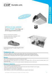
■ 2-way mixing box: CM2<br />
Air handling<br />
units<br />
<strong>AIR</strong> <strong>COMP</strong><strong>ACT</strong><br />
Box enabling fresh air and return air to be mixed by a moving vane ensuring flow metering and distribution.<br />
Manual and motorisable control.<br />
■ 3-way mixing box: CM3<br />
Box enabling removal of extracted air, introduction of fresh air and<br />
air recycling via the intermediary of two moving vanes ensuring<br />
flow metering and distribution.<br />
Manual and motorisation control possible.<br />
HI HS SI<br />
■ Straight or Curved Plenums: PLD PRS<br />
Can be mounted on either intake or discharge.<br />
2 plenum types:<br />
- intake or direct discharge: frame with double deflection<br />
grille, length 25 mm.<br />
- intake or discharge at RIGHT ANGLE: fitted with a double<br />
deflection grille, length 330 mm.<br />
PLD<br />
PRS<br />
■ Filtration<br />
In addition to a full section G4 filter base assembly,<br />
the following solutions are available: G4, F5 pleated, F6-F7-<br />
F8-F9 rigid pockets in universal sizes, with a compression<br />
system starting at filtration efficiency class F6.<br />
- Pressure taps mounted as standard on each stage.<br />
- Optional liquid filled pressure gauge.<br />
■ Hydraulic or evaporator coil in the AHU or<br />
vertical unit. CFV<br />
The coils are totally DRAINABLE. Piping is fitted with threaded<br />
ends with purge and drain plugs (Ø 1/8’’).<br />
- In heating mode:<br />
Size 25: 1, 2, and 3-row coils are available,<br />
Size 40 and 60: 1, 2, and 4-row coils are available,<br />
A frost protection thermostat with automatic reset can<br />
be installed on the coil.<br />
- In refrigeration mode:<br />
For each size there are 3, 4, and 6-row chilled water coils and<br />
3, 6 rows of direct expansion coils.<br />
The section is fitted with an eliminator, maximum face velocity:<br />
3.1 m/s and a stainless steel condensate container.<br />
Container isolation option using closed-cell foam.<br />
For vertical applications, max 4 rows in the CFV unit.<br />
2<br />
<strong>AIR</strong> CONDITIONING - HEATING - REFRIGERATION - <strong>AIR</strong> HANDLING - HEAT EXCHANGE - NA 08.637 A
Air handling<br />
units<br />
■ Electric heater<br />
The electric heater can be installed in the AHU (Power module<br />
1) or in an additional BEC unit (Power module 1 or module 2).<br />
It is fitted with 2 safety devices: 1 thermostat with automatic<br />
reset and 1 Klixon with manual reset.<br />
Depending on the nature of elements adjacent to the electric<br />
heater, (filter or motor, for example), a radiation shield may be<br />
installed upstream or downstream.<br />
■ Sound attenuator<br />
Fitted with a horizontal sound attenuator, height 200 mm, length 600 mm.<br />
■ Plate recuperator<br />
Three-phase 400-Volt configurations are available<br />
<strong>AIR</strong> <strong>COMP</strong><strong>ACT</strong><br />
Plate recuperator, aligned arrangement 25, 40, 60 size or offset arrangement 25 and 40 size: available in 2008.<br />
Fresh Air<br />
Extracted Air<br />
Return<br />
air<br />
Fresh Air<br />
Return air<br />
Discharged<br />
Air<br />
ALIGNED<br />
ALIGNED<br />
OFFSET<br />
(view from above)<br />
VENTILATION<br />
Single size fan (wheel size: 280mm) for the entire range. Selected for its excellent performance and sound level, as shown below:<br />
(See CURVES below)<br />
Air Compact 25<br />
Air Compact 40/1<br />
Air Compact 60<br />
Air Compact 40/2<br />
Total pressure (Pa)<br />
Air flowrate (m 3 /hr)<br />
Air Compact 25: fitted with 1 fan<br />
Air Compact 40: fitted with a choice of<br />
1 or 2 fans depending on flowrate<br />
Air Compact 60: fitted with 2 fans<br />
Fan without scroll (FREEWHEEL), with motor at shaft end,<br />
pressure range 100Pa min to 1000Pa max.<br />
<strong>AIR</strong> CONDITIONING - HEATING - REFRIGERATION - <strong>AIR</strong> HANDLING - HEAT EXCHANGE - NA 08.637 A<br />
3
Air handling<br />
units<br />
4 motor capacities are defined and cover the entire operating<br />
range:<br />
0.25 kW 4-pole; 0.55 kW 4-pole; 0.75 kW 2-pole; 1.50 kW 2-pole<br />
The frequency inverter is needed to reach the desired operating<br />
point.<br />
If there are 2 fan motor units, 1 single frequency inverter controls<br />
both motors.<br />
The frequency inverters are connected to a SINGLE PHASE<br />
230 V power supply and supply the motors with three-phase<br />
current. Optional frequency inverters with THREE PHASE 400 V<br />
supply<br />
<strong>AIR</strong> <strong>COMP</strong><strong>ACT</strong><br />
■ AHU arrangement designations<br />
CV1<br />
Motor in kW<br />
Frequency inverter type<br />
SK Single-phase 230V<br />
F2<br />
0.25 0.5M<br />
0.55 or 2X0.25 1.2M<br />
0.75 1.5M<br />
F2E<br />
2 X 0.55 2 M/TL<br />
1.5 or 2 X 0.75 2.5 M/TL<br />
2 X 1.5 4.5 M/TL<br />
F4<br />
F4E<br />
F5<br />
F5E<br />
F6<br />
Left: L<br />
Rights: R<br />
4<br />
<strong>AIR</strong> CONDITIONING - HEATING - REFRIGERATION - <strong>AIR</strong> HANDLING - HEAT EXCHANGE - NA 08.637 A
Air handling<br />
units<br />
■ Designations and lengths of additional units<br />
RA<br />
110 mm<br />
CM2<br />
400 mm<br />
PLD<br />
25 mm<br />
PRS<br />
330 mm<br />
CFA<br />
610 mm<br />
BEC<br />
610 mm<br />
CFV<br />
610 mm<br />
PLA<br />
1110 mm<br />
<strong>AIR</strong> <strong>COMP</strong><strong>ACT</strong><br />
CM3<br />
800 mm<br />
PAS<br />
610 mm<br />
CFR<br />
610 mm<br />
PLJ<br />
25 : 830 mm<br />
40 : 1400 mm<br />
SELECTION BY <strong>AIR</strong> <strong>COMP</strong><strong>ACT</strong> SOFTWARE<br />
Designations and lengths of air-handling units<br />
The software will<br />
determine the three<br />
types of air handling<br />
available based on<br />
the number of<br />
exchanger rows and<br />
the arrangement<br />
chosen.<br />
Example for F4:<br />
F4, F4p for two-stage<br />
filtration and F4b for a<br />
large number of coil<br />
rows.<br />
See table opposite.<br />
Pre-filtering<br />
Heating coil < 2 rows<br />
Cooling coil < 4 rows<br />
Ventilation<br />
only<br />
Ventilation<br />
Heating<br />
coil<br />
Ventilation<br />
Electric<br />
heater<br />
CV1<br />
F2<br />
F2E<br />
Pre-filtering<br />
Pocket filter<br />
Heating coil < 2 rows<br />
Cooling coil < 4 rows<br />
p<br />
CV1p<br />
610 mm 1100 mm<br />
830 mm<br />
*<br />
1100 mm<br />
F2p<br />
F2Ep<br />
1400 mm<br />
1400 mm<br />
Pre-filtering<br />
Heating coil < 2 rows < 4<br />
Cooling coil < 4 rows < 6<br />
F2b<br />
b<br />
1100 mm<br />
Ventilation<br />
Hot coil<br />
Cold coil<br />
F4<br />
1100 mm<br />
F4p<br />
1400 mm<br />
F4b<br />
1100 mm<br />
Ventilation<br />
Elec heater<br />
Cooling coil<br />
F4E<br />
1100 mm<br />
F4Ep<br />
1400 mm<br />
**<br />
F4Eb<br />
1100 mm<br />
Ventilation<br />
Cooling coil<br />
Heating coil<br />
F5<br />
1100 mm<br />
F5p<br />
1400 mm<br />
F5b<br />
1100 mm<br />
*CV1 610 mm with<br />
full-flow filters<br />
*CV1 830 mm<br />
universal sizes<br />
**RIGID opacimetric<br />
filters only<br />
Ventilation<br />
Cooling coil<br />
Elec heater<br />
Ventilation<br />
Cooling coil<br />
F5E<br />
F6<br />
1100 mm<br />
830 mm<br />
F5Eb<br />
F6p<br />
1400 mm<br />
1400 mm<br />
**<br />
F5Eb<br />
F6b<br />
1100 mm<br />
1100 mm<br />
<strong>AIR</strong> CONDITIONING - HEATING - REFRIGERATION - <strong>AIR</strong> HANDLING - HEAT EXCHANGE - NA 08.637 A<br />
5