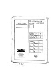
4 - Toma
4 - Toma
4 - Toma

Create successful ePaper yourself
Turn your PDF publications into a flip-book with our unique Google optimized e-Paper software.
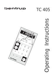
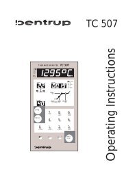
Further DisplaysThe indicators (8) and (9) show the actual status ON /OFF of the 1st (F0) resp. the 2nd (F1) relay output.By pressing the key (7) the controllers shows theactual power output (in %) on the display (4).Notes on theInstallation ManualThe controller TC802 is a member of the powerfulTC800 programme controllers. The installation andtherefore also the operating instructions of theinstallation (resp. configuration) are identical;however, some of the parameters and error messagesare not required because of the less complex structure(e.g. unused parameters 2, 4, 1., 2., 3., 5., B., D., E.).Maximum ValuesThe setpoint can be set in the range starting from 20°Cup to the maximum allowed value defined in theConfiguration.For safety reasons this maximum temperature shouldbe set to the limits of your system.bentrup industrial controls operating instructions TC802 version 4.X4
Er 6: Error on data acquisitionThe controller has determined a problem on data acquisition. The secondary code (shown in programdisplay) analyzes the problem:1: temperature values unsteady (problem on connectors of other high sensitive parts)2: internal problem in power supply (contact manufacturer)3: maximum temperature exceeded (see parameter list, could be caused by problems in relaycontactor or other components in the electronic system)Er 7: problem in external unitIf your controller is equipped with an optional expansion board (e.g. 0-20mA I/O) this error message point toa problem in this unit. For further details see manual of the corresponding board.Er 8: bad parameter listAfter power on the controller checks all values of the parameter list. If the adjusted values do no fit to thecurrent configuration or any other problem in the paramter list is found this error message is displayed. Seesecondary error code (on program display) for further details:1: zero calibration offset invalid2: checksum invalid3: jumper setting does not fit to configured thermocouple4: jumper setting does not fit to do0.0 (F0)-output configurationFor further details see parameter list in appendix B. To be able to re-configure software settings, you cansuppress this error message by unlocking the controller like in appendix B described.Er 9 : internal hardware problemThe controller performs a self-test after every start up. If this message will be displayed, please ask youdealer for further assistance.Er 0: firing interrupted because of power breakdownIf the firing process has been interrupted by a power breakdown (see chapter "Reaction on PowerBreakdown"), the controller shows this message. The program segment shows the ramp number where thepower breakdown happened.Note: This message also appears when the controller was turned off by the user before firing was completed(e.g. during last cooling segment). In this case the message doesn´t have any meaning.____________________________________________________________________________________________________________bentrup industrial controls TC800 series V4.x operating instructions 2
Selection 1 causes the kiln to determine the ramp direction (cooling / heating) by comparing the actual kilntemperature with the temperature of the first ramp. Example: Assuming that the 1st ramp temperatur is100°C and the kiln has already 200°C from last firing. On selection 1 the kiln will perform the 1st ramp as acooling starting from 200°C down to 100°C. On selection 0 the kiln will proceed with ramp 2 immediately.2.: condition for entering to next segment:0- segment will be finished when kiln temperature matches segment temperature1- segment will be finished when the programmed time is elapsed2- segment will be finished when both conditions are metSelection 0 is the default. Selection 1 should be taken the firing process has to fit to a fixed timetable. Useselection 2 if the kiln temperature is very unsteady and so a short temperature peak isn´t allowed to causethe controller to enter the next segment.3. Lock hour display for time:0- default: times will be entered starting from 0:00 til 80:00 hours1- times will be entered starting from 0 to 999 minutes4.: Suppress heating check:For security reasons the controllers checks the temperature gradient of the kilns continously and displays anerror message (Err 2) if the kiln temperature increase is too low even in full power heating. For someapplications this checking has to be suppressed (e.g. the kiln door has to be opened during firing; becauseof the heat escaping the kiln the controller will display an error Err 2 after a while; to avoid this use selection1 of this parameter)5.: lock program changes: To protect the programs against unauthorized changes set this parameter toselection 1. Can be used to save the once adjusted program set against unintentional change.6.: the output do0.0 (F0) can be used in different ways. This is to select the required mode:0- normal operation, do0.0 (F0) is output for heating the kiln1- as above, but for solid state relays2- ON during the total firing (can be used on 0-20mA operation)3- OFFImportant Note: Depending on the operation the do0.0 (F0) JUMPER has to be setted to "RELAY" (formechanical relay contactor) or to "SOL.STATE" (for solid state relay). The controller checks the propersetting of this JUMPER and displays an "Err 8" code 4 in case of failure.7.: operation of the do0.1 (F1)-output:0- OFF1- switches according event-bit no.12- switches according event-bit no. 23- ON during whole firing (e.g. for pilot flame on gas kilns)4- ON during firing, OFF during t05- ON when firing has finished6- ON if actual temperature higher than value x (see Parameter 8.)7- ON if actual temperature lower than value x (siehe Parameter 8.)8- ON if actual temperature higher than setpoint + x°C (see Parameter 8.)9- ON if actual temperature lower than setpoint - x °C (see Parameter 8.)10-ON if actual temperature in setpoint range of x°C (deviation alarm) (see Parameter 8.)11- control output cooling (see appendix D)12- beeper signal on temperature drop in fusing applications (TC803 fusing)13- security function: ouput is ON as long as the kiln temperature doesn´t exceed the programsmaximum temperatur plus x°C (see parameter 8.). If the kiln temperature goes too high this output isdeactivated to turn off kiln power and the controller displays "Er 5". Don´t select parameter 8. too small toavoid that the the security circuit reacts too sensitive (default value 30°C).14- ON if a error message occurs15- reserved for future applications____________________________________________________________________________________________________________bentrup industrial controls TC800 series V4.x operating instructions 5
8.: paramet- for do0.1 (F1)-output (see above)9.: operation of the do0.2 (F2)-output (see above)A.: parameter für do0.2 (F2)-output (see above)B.: communication interface mode:0- no data stream1- RS422 standard data stream2- as above, but additional information for multizone operation3- reservedC.: operation of the expansion board: In case of an installed expansion board you have to determine theoperation by setting this parameter:0- no I/O-board installed1- thyristor driver 0-20mA2- output of setpoint 0-20mA3- output of actual temperature 0-20mA4- additional input O 2 -sensor5- reservedD.: In case of multizone operation (with TC802-Z zone controller) the no. of zones has to be adjusted:0- no multizone operation1- multizone operation 1 zone2- multizone operation 2 zone3- ...The controllers needs this information to synchronize heat cycles of all zones. This results in very steadyheating (e.g. 30 seconds cylce time and 3 zones: zone 1 is activated, after 10 seconds zone 2 and thenagain after 10 seconds zone 3. After 10 seconds the 1 zone is activated again and so on)E.: This is to determine the temperature where the controller stops to control the kiln temperature during thelast decrease ramp. Also the "End" signal (see parameter E.) is determined by this value (not required forTC805/6).____________________________________________________________________________________________________________bentrup industrial controls TC800 series V4.x operating instructions 6
Appendix C:Control Parameters and Self-Optimization____________________________________________________________________________________The control algorithm of you TC800 series controller is mainly determined by the 3 parameters P, I and D.Explanation:- P is the proportional band (in % of the maximum temperature). This value determines the range oftemperature over that controller switches the kiln heating from 100% to 0%- I is the integral time (in seconds). This time determines the how fast the controllers minimizes theremaining temperature deviation to zero (note: Too small values cause the kiln temperature to oscillate)- D is the derivative time (in seconds). This value describes the kiln speedYour controller is equipped with a self-optimization-feature. During a special firing process the controller canfind out the best P, I , D values for optimal performance. On delivery there are standard parametersadjusted to ensure proper operation for nearly all kilns and applications. In most cases there is no need toperform the self optimization procedure.To perform the self optimization, proceed as follows:Unlock the controller like described in appendix B and press the [prog] button. The controller then shows thedefault optimization temperature (600°C). The controller will heat up the kiln til this temperature and will findout the best P,I,D values by monitoring the kilns reaction. You can adjust this optimization temperature byusing the buttons (9). The adjusting temperature should be about half the maximum kiln temperature.Pressing the button (7) will start the self-optimization process (segment display indicates ´A´for selfadjust)After the firing is finished (segment display is off) the controllers saves the calculated values automatically.These values can be called up by stepping through the parameter list (see appendix B). Note: If thecontroller is switched to a proportional band of 0.0% the self optimization function is not available.Appendix D:Cooling Output______________________________________________________________________________________On very slow cooling kilns a external cooling can be required. This can be done by flaps or fans. YourTC800 series controller can be programmed to control cooling instruments by configuring one of theadditional function outputs (see appendix B). Further information upon request.____________________________________________________________________________________________________________bentrup industrial controls TC800 series V4.x operating instructions 7
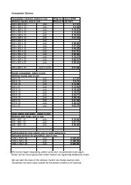
Configuration List TC800 Series Controllers______________________________________________________________________Customer:Date:Order Number:Kiln:Code Usage value range adjusted unit______________________________________________________________________________________0 configuration code 0-100 _________ -1 total operation hours counter 0-9999* _________ h2 reaction on power break down 0-2 _________ -3 %-heating in case of T/C error 0-60 _________ %4 power consumption of kiln 0-160 _________ kWh5 type of thermocouple: S - R - K - J * etc. 0-7 _________ -6 max. adjustable temperature * 20-1800 _________ °C7 max. allowed % of heating 0-100 _________ %8 proportional band 0.0-99.9 _________ %9 integral time** 10-8000 _________ sA minimum time for ON cycles** 0-15 _________ sB minimum time for OFF cycles** 0-15 _________ sC derivative time 0-999 _________ sD cylclus time** 1-100 _________ sE hysteresis** 0.5-25 _________ °CF reserved - _________ -0. unit for temperatures (°C or °F)* 0-1 _________ -1. unit for ramps (rate - time)*** 0-1 _________ -2. condition for entering next segment 0-2 _________ -3. lock hour display for time 0-1 _________ -4. suppress heating check (see Err 2) 0-1 _________ -5. lock program changes 0-1 _________ -6. output type do0.0 (F0) 0-3 _________ -7. output function do0.1 (F1) 0-15 _________ s8. optional parameter for do0.1 (F1) 0-4000 _________ -9. output function do0.2 (F2) 0-15 _________ sA. optional parameter for do0.2 (F2) 0-4000 _________ -B. communication interface mode 0-255 _________ -C. operation of I/O-expansion board 0-255 _________ -D. no. of zones on master operation 0-16 _________ -E. final temp. on program end (not for TC805/6) 0-1800 _________ °CRemarks:____________________________________________________________________________________________________________bentrup industrial controls TC800 series V4.x operating instructions 8
Appendix E:Assignment of the Receptables_______________________________________________The electrical connections are made by using receptables (6.3mm and 2.8mm). There are located on theback side of the controller. See below for assignement:LINENPE (Protection Earth)COM:common contact of relaysN/O:N/C:do0.0 (F0), do0.1 (F1), do0.2 (F2):power Supply 220V/50/60Hz (live)power Supply 200V/50/60Hz (live back)used by internal filters (supression EARTH)normal open contact (short to COM when relay energised)normal closed contact (short to COM when relay de-energised)connections of the corresponding relay, „do“ stands for „digital output“AI0.0 (T/C)+ : thermocouple +AI0.0 (T/C)- : thermocouple -RXTX+:RXTX-:EXP-X:EXP-Y:COM:communication interface + (optional)communication interface - (optional)input/Output of expansion board (optional, e.g. for 0-20mA thyristor)input/Output of expansion board (optional)common-conection of expansion board (optional)Important note for VLCD (very low currency devices): The relay outputs are bridged with an RCcombinationof 0.033uF+150R to supress sparks on switching. By using very low currency devices, this cancause problems because of the remaining currency that can flow over this RC-bridge even when the relay isde-energies (i.e. in OFF-position). If this is the case, adjust the JUMPER for do0.0 (F0) inside the controller(and re-configure parameter list) or use load resistors. Further informations can be required directly from us.Important note by using relay contactors: Relay contactors generate electromagnetical noise whenswitching. These can interfere with electronic devices. To supress these noise please use an RC-bridge anthe relay contactor coil (also required by the FCC restrictions).____________________________________________________________________________________________________________bentrup industrial controls TC800 series V4.x operating instructions 9