TC804 V4 Englisch - Toma
TC804 V4 Englisch - Toma
TC804 V4 Englisch - Toma
- No tags were found...

You also want an ePaper? Increase the reach of your titles
YUMPU automatically turns print PDFs into web optimized ePapers that Google loves.
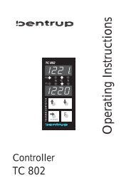
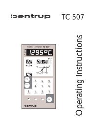
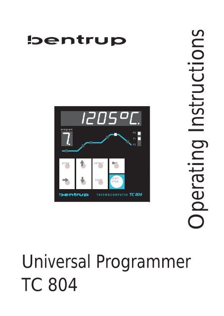
programprogkooselectkw/hstartstopF0F1F2THERMOCOMPUTERTC 804Operating InstructionsUniversal ProgrammerTC 804
Controllers Panel <strong>TC804</strong> / Brief Description(1) main display: reads actualtemperature and programme values(2) unit of the displayed value12(3) programme number: Thiswindows continuously shows thenumber (#1 to #9) of the currentlyselected programme.36programprogoselectF0F1F2458(4) sketch of the firing curve. The LEDpoints either to the actual segment orto the programme value actuallyentered (LED blinking)7kokw/hstartstopTHERMOCOMPUTERTC 80412(5) output indicators: ON/OFF statusof the control outputs F0 / F1 / F2.91011(6) key programme select: Press this key to select programmes number #1 to #9. Eachpressing of the key increments the programme number by one.(7) To enter a new programme or to change the values of the actually selected programme,select the segment number by these keys (segment display (4) is blinking).(8) Key to lock / unlock the keyboard (press and hold for 3 seconds). A locked display isindicated by the decimal point in display 3 (as shown)(9) key to change programme values: If a programme value is shown in the main window,you can change it using these keys. For larger value changes, hold the key pressed.(10) key to change the value of the EVENT bit(11) key kw/h: To display power consumption since the last start of the firing. If the key ispressed 3 seconds, the <strong>TC804</strong> enters the installation (For details see appendix B).(12) start / stop key: Press this key to start the actual programme. The controller shows aflashing decimal point on the main display to indicate a running programme. To stop theprogramme, press start / stop again (Decimal point stops blinking).
Kiln Controller <strong>TC804</strong>_______________________________________________________________________________________1.) General InformationBy using the controller <strong>TC804</strong> you can determine the exact course of your kiln firing. You can program up to9 firing curves according to your application.The electrical connections to the <strong>TC804</strong> are made by using receptables (6.3mm/2.8mm). The controllermust not be exposed to high temperature, extreme humidity or mechanical demage and must be connectedto a stable power supply.To avoid use by unauthorized persons the keyboard can be locked by pressing the "key-button" for 3seconds (only during a running program). The decimal point appearing on the program display (3) indicatesthat the keyboard is locked. To unlock press the "key-button" again for 3 seconds.2.) Getting StartedUpon switch ´on´ the <strong>TC804</strong> shows the internal software version (e.g. "V 4.7": version 4.7) and thenindicates the kiln temperature in the upper display. If this is not the case, you should check whethera) the kiln control circuit fuse is switched onb) your kiln is connected with the power supplyc) the controller's fuse has a defect (the fuse is located inside the controller)3.) Explanations of the TermsOn the front of your controller are the following keys:select next segment of the curve(key) key-button for locking the controlleradjust displayed valueevent adjust the event output per segmenttotal kwH display the power consumption of the previous firingprog select program for firing or changingstart/stop start/stop the firing processOn the controllers frontside the firing course is shown as a firing curve consisting of six segments. A typicalfiring curve includes the following segments (hrs:min = hours:minutes reading):a. program delay (hrs:min)b. heat up ramp (°C per hour or hrs:min)c. 1 st dwell (°C and hrs:min)d. heat up ramp (°C per hour or hrs:min)e. 2 nd dwell (°C and hrs:min)f. cool down ramp (°C per hour or hrs:min)Program delay:The <strong>TC804</strong> controller has a program delay function (segment a., see above) which can be used for delayedstart. This can be used to take advantage of "off peak" electricity.The <strong>TC804</strong> provides the feature to have the 1st dwell (c.) at a higher temperature than 2nd dwell (e.). Thiscan be helpful for glass applications: heat up to 1st dwell at e.g. 820°C, then cooling down to 560°C insegment (d.). After the 2nd dwell a slow cooling can be done by using segment (f.).______________________________________________________________________________________________________________________bentrup industrial controls <strong>TC804</strong> <strong>V4</strong>.x operating instructions 1
The ramp segments (b., d., f.) are equipped with two 2 special features that are activated by counting thevalue in the segment to the upper end (lower end resp.). The value "SKIP" causes the controller to heat up(cool down resp.) with maximum speed (i.e. uncontrolled). The value "END" causes the controller to end thefiring disregarding the following segments. Last function can be useful e.g. for a simple drying program:segment (b.) 30°C/h to 150°C, 20 min dwelling and then program stop. Set ramp segment (d.) to "END" forthis firing curve.4.) Entering a ProgramOn delivery the 9 programs are unassigned. To enter a program curve proceed as follows:- select the desired program no. by using key (6)(the controllers shows the firing temperature of each selected program)- by pressing the key (7) you can select all segments of the curve- by using the arrow keys (9) you can change the program values as requiredAfter pressing the "start stop" key (12) the firing starts (the decimal point is flashing on the very right handside of the display (1) indicating that a firing process is actually running. The display (1) shows the actualkiln´s temperature.5.) ProgramsYou can store up to 9 programs in your <strong>TC804</strong> controller. Therefore you can store your most useful firingcycles. To enter a program you have to call up a program number before entering the curve values. Whenyou have finished entering the curve the controller saves it automatically.To start a saved program proceed as follows: Press the button (6) multiple times until the desired programnumber appears on the program display (3). After pressing the button (12) the controller starts firing.6.) Displaying Values while FiringDuring a firing the controller indicates the kiln temperature on the upper display (during a delay start thecontroller indicates the remaining time in minutes/hours before the firing starts). The actual segment of thefiring curve is also shown in display (4).You can also change the firing curve while the program is running. Press button (7) to display the parameterof the firing curve and change them by using buttons (9). The display returns to kiln temperature 15 secondsafter the last adjustment has been done.Note: If you change the time for dwell of the actual running segment, you only change the value for thisfiring (i.e. the programs time value is not affected).There are 4 values that can be displayed during a firing without interrupting the firing:- program setpoint (by pressing button)- actual kiln heating in % of power,(by pressing button)- time remaining in a segment (by pressing the "event"-button)- power consumption of firing (button (11); will be reset to zero after selection of new program)After 2 seconds the display changes automatically back to the normal indication.______________________________________________________________________________________________________________________bentrup industrial controls <strong>TC804</strong> <strong>V4</strong>.x operating instructions 2
7.) Reaction to a break down of Power SupplyYou can adjust the reaction to a power break down:- stop firing with displaying the error message F0 (0)- continue firing if the break down was shorter than 30 Minutes (1)- continue firing after the power supply is established again (2)The number in brackets is the value you have to adjust in the configuration table of you controller (seeappendix). The controller is preadjusted to mode (1) (continue if break down < 30 min).8.) Direct ControlIn certain applications it may be useful to take direct control of the firing process (e.g. for glass fusing).Therefore you have the following functions (only while program is running):8.1.) Immediate skipping to the next SegmentThe user sees that the time in the actual segment is too long that means that the controller is supposed tocontinue with the next segment. By pressing the button "event" (10) for 3 seconds the controller will skip tothe next segment immediately.8.2.) "Hold" in the actual SegmentThe user sees that the goods need more time than the duration of the segment provides. By pressing thekey "prog" (6) for 3 seconds you can set the controller to hold mode: The holding times can be extended inaddition the given temperature during the ramps stays constant (the setpoint is no longer driven up ordown). This hold mode is indicated by a "h" in the program display (3). The hold mode is released bypressing the "prog" button (6) again for 3 seconds.8.3.) Predefined "Hold"The user can set the kiln to the hold mode (see above) at a predefined segment of the firing. The time valueof the segment where the controller has to enter the "hold" mode will be set to "hold" (this is done byincreasing the time to maximum value + 1). Please note that the controller will stay in hold mode until theuser continues the program by pressing the prog button (6) for 3 seconds.9.) Maximal Range for Valuesa.) times ...........................................................................................0:00 to 80:00 hoursb.) ramps..........................................................................................0 to 700°C, SKIP, ENDc.) temperatures ...............................................................................20°C - (depending on kiln)10.) Additional Event OutputYour controller <strong>TC804</strong> can be configured for up to two additional event outputs. You can program theseevent outputs for every segment "ON" of "OFF". By using this you can control any additional instruments forfiring (flaps, gas control, warning signals etc.).After you have selected a segment by using the buttons (7,8) press the button [event] (10). The displayshows "E1" or "E2" (event 1 or 2) and the actual programmed status, 0=ON or 1=OFF. You can change thestatus by pressing one of the keys (9). This information (ON of OFF) has to be programmed for everysegment of the curve and will also be saved in a program.______________________________________________________________________________________________________________________bentrup industrial controls <strong>TC804</strong> <strong>V4</strong>.x operating instructions 3
Appendix A:Error Messages of the TC800 Series Controllers_______________________________________________During firing TC800 series controllers check all units of the kiln. If a problem occurs the controller displays"Er " followed by a number (Error No.) and an optional secondary code that is shown in the programdisplay.Er 1: no program is selected or program values badIf you try to start firing without having previously selected a valid program the controller shows this errormessage. Select a program by pressing the button (12)Er 2: kiln does not follow the required temperature increaseAlthough the kiln heats with full power the temperature increase during the heat up is too small (at least 1°Cper 16 min). The cause of fault must be recognized exactly to avoid problems with further firing procedures.possible cause of the fault : required temperature increase exceeds kiln powerfuse defectdoor switch openedheating elements too old of heating element failureIn some applications it is required to supress this checking. Refer to parameter 4. (appendix B).Er 3: Thermocouple or electrical link (cable) is defectCheck all connections and wires (connectors, cable damage, thermocouple destroyed ..)Er 4: Thermocouple polarity incorrectpossible cause of fault :temperature sensor itself incorrect polarizedtemperature sensor colder than -15°CEr 5: safety alarm activatedIf one of the additional outputs is confugured as a safety alarm and the alarm conditions occured, thismessage will be shown.Check all units of your kiln (relay contactors, solid stated relay etc.)____________________________________________________________________________________________________________bentrup industrial controls TC800 series <strong>V4</strong>.x operating instructions 1
Er 6: Error on data acquisitionThe controller has determined a problem on data acquisition. The secondary code (shown in programdisplay) analyzes the problem:1: temperature values unsteady (problem on connectors of other high sensitive parts)2: internal problem in power supply (contact manufacturer)3: maximum temperature exceeded (see parameter list, could be caused by problems in relaycontactor or other components in the electronic system)Er 7: problem in external unitIf your controller is equipped with an optional expansion board (e.g. 0-20mA I/O) this error message point toa problem in this unit. For further details see manual of the corresponding board.Er 8: bad parameter listAfter power on the controller checks all values of the parameter list. If the adjusted values do no fit to thecurrent configuration or any other problem in the paramter list is found this error message is displayed. Seesecondary error code (on program display) for further details:1: zero calibration offset invalid2: checksum invalid3: jumper setting does not fit to configured thermocouple4: jumper setting does not fit to do0.0 (F0)-output configurationFor further details see parameter list in appendix B. To be able to re-configure software settings, you cansuppress this error message by unlocking the controller like in appendix B described.Er 9 : internal hardware problemThe controller performs a self-test after every start up. If this message will be displayed, please ask youdealer for further assistance.Er 0: firing interrupted because of power breakdownIf the firing process has been interrupted by a power breakdown (see chapter "Reaction on PowerBreakdown"), the controller shows this message. The program segment shows the ramp number where thepower breakdown happened.Note: This message also appears when the controller was turned off by the user before firing was completed(e.g. during last cooling segment). In this case the message doesn´t have any meaning.____________________________________________________________________________________________________________bentrup industrial controls TC800 series <strong>V4</strong>.x operating instructions 2
Appendix B:How to configure the controller TC800 series______________________________________________________________________________________To get the best performance, you have to adjust some parameters that determine the operation of thecontrollers. The parameters are pre-setted to standard values that ensure proper operation in most cases.But for optimal usage, we recommand to set the parameter list. This has only to be done once.Changing the ParametersTo avoid unauthorized changing, the parameters are locked. For unlocking proceed as follows: Turn off thecontroller, press button [total kwh] and turn on the controller again (hold button pressed). The controllersshows a "C" for "configuration" on the program display. The controller is now in configuration mode with thefollowing consequences:- by pressing the [prog]-button the self-adjust-firing can be started (see below)- a error message "Er 8" is supressed to allow new configuration- the parameter list can be changedTo get in the parameter menu press the button "total KwH" and hold it for about 4 seconds. Now the displayshows the first configurable value. You can change the value by pressing the buttons (9). Next parameterwill be called up by pressing the button (7) and so on.Important: To ensure that all values will be saved correctly you have to leave this menu by pressing thebutton (7) until all parameters are stepped through. Bad operation will cause an "Err 8" error !Code Usage value range unit______________________________________________________________________________________0 configuration code 0-100 -1 total operation hours counter 0-9999* h2 reaction on power break down 0-2 -3 %-heating in case of T/C error 0-60 %4 power consumption of kiln 0-160 kWh5 type of thermocouple: S - R - K - J * etc. 0-7 -6 max. adjustable temperature * 20-1800 °C7 max. allowed % of heating 0-100 %8 proportional band 0.0-99.9 %9 integral time** 10-8000 sA minimum time for ON cycles** 0-15 sB minimum time for OFF cycles** 0-15 sC derivative time 0-999 sD cylclus time** 1-100 sE hysteresis** 0.5-25 °CF reserved - -0. unit for temperatures (°C or °F)* 0-1 -1. unit for ramps (rate - time)*** 0-1 -2. condition for entering next segment 0-2 -3. lock hour display for time 0-1 -4. suppress heating check (see Err 2) 0-1 -5. lock program changes 0-1 -6. output type do0.0 (F0) 0-3 -7. output function do0.1 (F1) 0-15 s8. optional parameter for do0.1 (F1) 0-4000 -9. output function do0.2 (F2) 0-15 sA. optional parameter for do0.2 (F2) 0-4000 -B. communication interface mode 0-255 -C. operation of I/O-expansion board 0-255 -D. no. of zones on master operation 0-16 -E. final temp. on program end (not for TC805/6) 0-1800 °C* parameter locked to prevent from unauthorized change. Please request additonal code from manufacturer** depending on the proportional band (0.0% or >0.0%) some parameters are skipped*** On TC805/6: starting temperature on 1st ramp 20°C or actual kiln temperature____________________________________________________________________________________________________________bentrup industrial controls TC800 series <strong>V4</strong>.x operating instructions 3
Explanation of the Paramters0: This is a free adjustable value to inform further users about the origin/type of configuration. It can be usede.g. to leave a mark in the controller.1: The controller summarizes all operation cycles of the kiln heating elements. This parameter shows youthe total time in hours and is very helpful for checking the kilns lifetime (warranty etc.). For resettingadditional code required2: reaction on power break down:0- stop firing (see Error message Er 0)1- resume firing if power break down less than 20 minutes2- resume firind unconditional3: If a problem during firing occurs and the controller is forced to interrupt in some applications a small(uncontrolled) heating may be useful. This prevents from fast temperature decrease. For security reasonsthis percantage value is limited to 60%.4: The controllers takes this value to calculate the power consumption. The power consumption can becalled up by pressing the [total kwh] - button during firing (see manual).5: type of thermocouple: the controller can be adjusted to on of the following thermocouples:0- Typ S (Pt 10%)1- Typ R (Pt13%)2- Typ K (NiCr)3- Typ J (FeCu)Important note: This adjustment requires also proper setting of one JUMPER on the controller board. Forparameter 0 and 1 the T/C JUMPER has to be setted on S/R position, for parameter 2 and 3 to K/J position.The controller checks the JUMPER position after every restart and displays "Err 8" code 3 in case of failure.6: This value limits the maximum temperature that can be programmed (usually the maximum kilntemperature). For changing of parameters 4 and 5 additional code required.7: This value can be used to limit the maximum heating power (to use on kilns that are not allowed to havethe maximum power of heating). The value is given in percent.8: proportional band - control parameter, self adjust feature see below. A value of 0.0% causes thecontroller to operate as a hysteresis controller with D-function. Might be required for very fast reacting kilns.9: integral time, control parameter, self adjust feature see below (not required if prop.band =0.0%)A: minimum ON cyclus time (on PB=0.0% only): Some applications require to extend the minimum cyclustime (e.g. on some gas kilns very short heat cycles are not allowed on low temperatures)B: minimum OFF cyclus time (on PB=0.0% only): see above, but OFF time is extended if required.C: derivative time, control parameter, self adjust feature see belowD: The cycle time determines frequency of switching. A short time (e.g. 10 sec) causes a very smoothheating but a high loss of the relay contactor. A long time increases the lifetime of the relay but results inunsteady kiln heating. A time of 30 seconds is the best value for most applications.E: Hysterisis: (on PB=0.0% only): A low hysterisis provides faster and accurate control; see aboveF: Reseved for future applications0.: Units °C / °F: Changing this parameter to 1 causes the controller to switch to °F display. All values will beprocessed in °F. (Tmp(°F) = Tmp(°C) * 9 / 5 + 32).1: this is to select the way to determine the ramp values not ( onTC805/6):0- ramps determined by rate (2-700°C/h, SKIP, End)(e.g. ramp 450°C/h to next hold temperatur 600°C)1- ramps determined by time (End, SKIP, 2-999 min)(e.g. ramp takes 100 min to next hold temperature 600°C)on TC805/6: The starting temperature for calculating the 1st ramp can be selected:0- temperature of 20°C1- actual kiln temperature____________________________________________________________________________________________________________bentrup industrial controls TC800 series <strong>V4</strong>.x operating instructions 4
Selection 1 causes the kiln to determine the ramp direction (cooling / heating) by comparing the actual kilntemperature with the temperature of the first ramp. Example: Assuming that the 1st ramp temperatur is100°C and the kiln has already 200°C from last firing. On selection 1 the kiln will perform the 1st ramp as acooling starting from 200°C down to 100°C. On selection 0 the kiln will proceed with ramp 2 immediately.2.: condition for entering to next segment:0- segment will be finished when kiln temperature matches segment temperature1- segment will be finished when the programmed time is elapsed2- segment will be finished when both conditions are metSelection 0 is the default. Selection 1 should be taken the firing process has to fit to a fixed timetable. Useselection 2 if the kiln temperature is very unsteady and so a short temperature peak isn´t allowed to causethe controller to enter the next segment.3. Lock hour display for time:0- default: times will be entered starting from 0:00 til 80:00 hours1- times will be entered starting from 0 to 999 minutes4.: Suppress heating check:For security reasons the controllers checks the temperature gradient of the kilns continously and displays anerror message (Err 2) if the kiln temperature increase is too low even in full power heating. For someapplications this checking has to be suppressed (e.g. the kiln door has to be opened during firing; becauseof the heat escaping the kiln the controller will display an error Err 2 after a while; to avoid this use selection1 of this parameter)5.: lock program changes: To protect the programs against unauthorized changes set this parameter toselection 1. Can be used to save the once adjusted program set against unintentional change.6.: the output do0.0 (F0) can be used in different ways. This is to select the required mode:0- normal operation, do0.0 (F0) is output for heating the kiln1- as above, but for solid state relays2- ON during the total firing (can be used on 0-20mA operation)3- OFFImportant Note: Depending on the operation the do0.0 (F0) JUMPER has to be setted to "RELAY" (formechanical relay contactor) or to "SOL.STATE" (for solid state relay). The controller checks the propersetting of this JUMPER and displays an "Err 8" code 4 in case of failure.7.: operation of the do0.1 (F1)-output:0- OFF1- switches according event-bit no.12- switches according event-bit no. 23- ON during whole firing (e.g. for pilot flame on gas kilns)4- ON during firing, OFF during t05- ON when firing has finished6- ON if actual temperature higher than value x (see Parameter 8.)7- ON if actual temperature lower than value x (siehe Parameter 8.)8- ON if actual temperature higher than setpoint + x°C (see Parameter 8.)9- ON if actual temperature lower than setpoint - x °C (see Parameter 8.)10-ON if actual temperature in setpoint range of x°C (deviation alarm) (see Parameter 8.)11- control output cooling (see appendix D)12- beeper signal on temperature drop in fusing applications (TC803 fusing)13- security function: ouput is ON as long as the kiln temperature doesn´t exceed the programsmaximum temperatur plus x°C (see parameter 8.). If the kiln temperature goes too high this output isdeactivated to turn off kiln power and the controller displays "Er 5". Don´t select parameter 8. too small toavoid that the the security circuit reacts too sensitive (default value 30°C).14- ON if a error message occurs15- reserved for future applications____________________________________________________________________________________________________________bentrup industrial controls TC800 series <strong>V4</strong>.x operating instructions 5
8.: paramet- for do0.1 (F1)-output (see above)9.: operation of the do0.2 (F2)-output (see above)A.: parameter für do0.2 (F2)-output (see above)B.: communication interface mode:0- no data stream1- RS422 standard data stream2- as above, but additional information for multizone operation3- reservedC.: operation of the expansion board: In case of an installed expansion board you have to determine theoperation by setting this parameter:0- no I/O-board installed1- thyristor driver 0-20mA2- output of setpoint 0-20mA3- output of actual temperature 0-20mA4- additional input O 2 -sensor5- reservedD.: In case of multizone operation (with TC802-Z zone controller) the no. of zones has to be adjusted:0- no multizone operation1- multizone operation 1 zone2- multizone operation 2 zone3- ...The controllers needs this information to synchronize heat cycles of all zones. This results in very steadyheating (e.g. 30 seconds cylce time and 3 zones: zone 1 is activated, after 10 seconds zone 2 and thenagain after 10 seconds zone 3. After 10 seconds the 1 zone is activated again and so on)E.: This is to determine the temperature where the controller stops to control the kiln temperature during thelast decrease ramp. Also the "End" signal (see parameter E.) is determined by this value (not required forTC805/6).____________________________________________________________________________________________________________bentrup industrial controls TC800 series <strong>V4</strong>.x operating instructions 6
Appendix C:Control Parameters and Self-Optimization____________________________________________________________________________________The control algorithm of you TC800 series controller is mainly determined by the 3 parameters P, I and D.Explanation:- P is the proportional band (in % of the maximum temperature). This value determines the range oftemperature over that controller switches the kiln heating from 100% to 0%- I is the integral time (in seconds). This time determines the how fast the controllers minimizes theremaining temperature deviation to zero (note: Too small values cause the kiln temperature to oscillate)- D is the derivative time (in seconds). This value describes the kiln speedYour controller is equipped with a self-optimization-feature. During a special firing process the controller canfind out the best P, I , D values for optimal performance. On delivery there are standard parametersadjusted to ensure proper operation for nearly all kilns and applications. In most cases there is no need toperform the self optimization procedure.To perform the self optimization, proceed as follows:Unlock the controller like described in appendix B and press the [prog] button. The controller then shows thedefault optimization temperature (600°C). The controller will heat up the kiln til this temperature and will findout the best P,I,D values by monitoring the kilns reaction. You can adjust this optimization temperature byusing the buttons (9). The adjusting temperature should be about half the maximum kiln temperature.Pressing the button (7) will start the self-optimization process (segment display indicates ´A´for selfadjust)After the firing is finished (segment display is off) the controllers saves the calculated values automatically.These values can be called up by stepping through the parameter list (see appendix B). Note: If thecontroller is switched to a proportional band of 0.0% the self optimization function is not available.Appendix D:Cooling Output______________________________________________________________________________________On very slow cooling kilns a external cooling can be required. This can be done by flaps or fans. YourTC800 series controller can be programmed to control cooling instruments by configuring one of theadditional function outputs (see appendix B). Further information upon request.____________________________________________________________________________________________________________bentrup industrial controls TC800 series <strong>V4</strong>.x operating instructions 7
Configuration List TC800 Series Controllers______________________________________________________________________Customer:Date:Order Number:Kiln:Code Usage value range adjusted unit______________________________________________________________________________________0 configuration code 0-100 _________ -1 total operation hours counter 0-9999* _________ h2 reaction on power break down 0-2 _________ -3 %-heating in case of T/C error 0-60 _________ %4 power consumption of kiln 0-160 _________ kWh5 type of thermocouple: S - R - K - J * etc. 0-7 _________ -6 max. adjustable temperature * 20-1800 _________ °C7 max. allowed % of heating 0-100 _________ %8 proportional band 0.0-99.9 _________ %9 integral time** 10-8000 _________ sA minimum time for ON cycles** 0-15 _________ sB minimum time for OFF cycles** 0-15 _________ sC derivative time 0-999 _________ sD cylclus time** 1-100 _________ sE hysteresis** 0.5-25 _________ °CF reserved - _________ -0. unit for temperatures (°C or °F)* 0-1 _________ -1. unit for ramps (rate - time)*** 0-1 _________ -2. condition for entering next segment 0-2 _________ -3. lock hour display for time 0-1 _________ -4. suppress heating check (see Err 2) 0-1 _________ -5. lock program changes 0-1 _________ -6. output type do0.0 (F0) 0-3 _________ -7. output function do0.1 (F1) 0-15 _________ s8. optional parameter for do0.1 (F1) 0-4000 _________ -9. output function do0.2 (F2) 0-15 _________ sA. optional parameter for do0.2 (F2) 0-4000 _________ -B. communication interface mode 0-255 _________ -C. operation of I/O-expansion board 0-255 _________ -D. no. of zones on master operation 0-16 _________ -E. final temp. on program end (not for TC805/6) 0-1800 _________ °CRemarks:____________________________________________________________________________________________________________bentrup industrial controls TC800 series <strong>V4</strong>.x operating instructions 8
Appendix E:Assignment of the Receptables_______________________________________________The electrical connections are made by using receptables (6.3mm and 2.8mm). There are located on theback side of the controller. See below for assignement:LINENPE (Protection Earth)COM:common contact of relaysN/O:N/C:do0.0 (F0), do0.1 (F1), do0.2 (F2):power Supply 220V/50/60Hz (live)power Supply 200V/50/60Hz (live back)used by internal filters (supression EARTH)normal open contact (short to COM when relay energised)normal closed contact (short to COM when relay de-energised)connections of the corresponding relay, „do“ stands for „digital output“AI0.0 (T/C)+ : thermocouple +AI0.0 (T/C)- : thermocouple -RXTX+:RXTX-:EXP-X:EXP-Y:COM:communication interface + (optional)communication interface - (optional)input/Output of expansion board (optional, e.g. for 0-20mA thyristor)input/Output of expansion board (optional)common-conection of expansion board (optional)Important note for VLCD (very low currency devices): The relay outputs are bridged with an RCcombinationof 0.033uF+150R to supress sparks on switching. By using very low currency devices, this cancause problems because of the remaining currency that can flow over this RC-bridge even when the relay isde-energies (i.e. in OFF-position). If this is the case, adjust the JUMPER for do0.0 (F0) inside the controller(and re-configure parameter list) or use load resistors. Further informations can be required directly from us.Important note by using relay contactors: Relay contactors generate electromagnetical noise whenswitching. These can interfere with electronic devices. To supress these noise please use an RC-bridge anthe relay contactor coil (also required by the FCC restrictions).____________________________________________________________________________________________________________bentrup industrial controls TC800 series <strong>V4</strong>.x operating instructions 9