EMCS: Site Requirements, Applications and Systems Sequences of ...
EMCS: Site Requirements, Applications and Systems Sequences of ...
EMCS: Site Requirements, Applications and Systems Sequences of ...
Create successful ePaper yourself
Turn your PDF publications into a flip-book with our unique Google optimized e-Paper software.
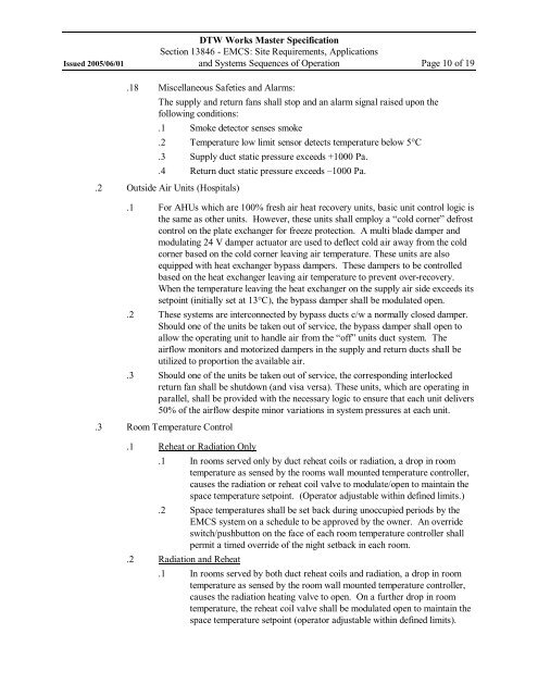
DTW Works Master SpecificationSection 13846 <strong>EMCS</strong>: <strong>Site</strong> <strong>Requirements</strong>, <strong>Applications</strong>Issued 2005/06/01 <strong>and</strong> <strong>Systems</strong> <strong>Sequences</strong> <strong>of</strong> Operation Page 10 <strong>of</strong> 19.18 Miscellaneous Safeties <strong>and</strong> Alarms:The supply <strong>and</strong> return fans shall stop <strong>and</strong> an alarm signal raised upon thefollowing conditions:.1 Smoke detector senses smoke.2 Temperature low limit sensor detects temperature below 5°C.3 Supply duct static pressure exceeds +1000 Pa..4 Return duct static pressure exceeds –1000 Pa..2 Outside Air Units (Hospitals).1 For AHUs which are 100% fresh air heat recovery units, basic unit control logic isthe same as other units. However, these units shall employ a “cold corner”defrostcontrol on the plate exchanger for freeze protection. A multi blade damper <strong>and</strong>modulating 24 V damper actuator are used to deflect cold air away from the coldcorner based on the cold corner leaving air temperature. These units are alsoequipped with heat exchanger bypass dampers. These dampers to be controlledbased on the heat exchanger leaving air temperature to prevent overrecovery.When the temperature leaving the heat exchanger on the supply air side exceeds itssetpoint (initially set at 13°C), the bypass damper shall be modulated open..2 These systems are interconnected by bypass ducts c/w a normally closed damper.Should one <strong>of</strong> the units be taken out <strong>of</strong> service, the bypass damper shall open toallow the operating unit to h<strong>and</strong>le air from the “<strong>of</strong>f”units duct system. Theairflow monitors <strong>and</strong> motorized dampers in the supply <strong>and</strong> return ducts shall beutilized to proportion the available air..3 Should one <strong>of</strong> the units be taken out <strong>of</strong> service, the corresponding interlockedreturn fan shall be shutdown (<strong>and</strong> visa versa). These units, which are operating inparallel, shall be provided with the necessary logic to ensure that each unit delivers50% <strong>of</strong> the airflow despite minor variations in system pressures at each unit..3 Room Temperature Control.1 Reheat or Radiation Only.1 In rooms served only by duct reheat coils or radiation, a drop in roomtemperature as sensed by the rooms wall mounted temperature controller,causes the radiation or reheat coil valve to modulate/open to maintain thespace temperature setpoint. (Operator adjustable within defined limits.).2 Space temperatures shall be set back during unoccupied periods by the<strong>EMCS</strong> system on a schedule to be approved by the owner. An overrideswitch/pushbutton on the face <strong>of</strong> each room temperature controller shallpermit a timed override <strong>of</strong> the night setback in each room..2 Radiation <strong>and</strong> Reheat.1 In rooms served by both duct reheat coils <strong>and</strong> radiation, a drop in roomtemperature as sensed by the room wall mounted temperature controller,causes the radiation heating valve to open. On a further drop in roomtemperature, the reheat coil valve shall be modulated open to maintain thespace temperature setpoint (operator adjustable within defined limits).


