DTW Works Master Specification Section 15131 - Pumps - Hydronic ...
DTW Works Master Specification Section 15131 - Pumps - Hydronic ...
DTW Works Master Specification Section 15131 - Pumps - Hydronic ...
You also want an ePaper? Increase the reach of your titles
YUMPU automatically turns print PDFs into web optimized ePapers that Google loves.
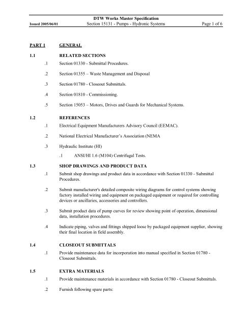
<strong>DTW</strong> <strong>Works</strong> <strong>Master</strong> <strong>Specification</strong>Issued 2005/06/01 <strong>Section</strong> <strong>15131</strong> <strong>Pumps</strong> <strong>Hydronic</strong> Systems Page 1 of 6PART 1GENERAL1.1 RELATED SECTIONS.1 <strong>Section</strong> 01330 Submittal Procedures..2 <strong>Section</strong> 01355 –Waste Management and Disposal.3 <strong>Section</strong> 01780 Closeout Submittals..4 <strong>Section</strong> 01810 Commissioning..5 <strong>Section</strong> 15053 –Motors, Drives and Guards for Mechanical Systems.1.2 REFERENCES.1 Electrical Equipment Manufacturers Advisory Council (EEMAC)..2 National Electrical Manufacturer’s Association (NEMA.3 Hydraulic Institute (HI).1 ANSI/HI 1.6 (M104) Centrifugal Tests.1.3 SHOP DRAWINGS AND PRODUCT DATA.1 Submit shop drawings and product data in accordance with <strong>Section</strong> 01330 SubmittalProcedures..2 Submit manufacturer's detailed composite wiring diagrams for control systems showingfactory installed wiring and equipment on packaged equipment or required for controllingdevices or ancillaries, accessories and controllers..3 Submit product data of pump curves for review showing point of operation, dimensionaldata, installation procedures..4 Indicate piping, valves and fittings shipped loose by packaged equipment supplier, showingtheir final location in field assembly.1.4 CLOSEOUT SUBMITTALS.1 Provide maintenance data for incorporation into manual specified in <strong>Section</strong> 01780 Closeout Submittals.1.5 EXTRA MATERIALS.1 Provide maintenance materials in accordance with <strong>Section</strong> 01780 Closeout Submittals..2 Furnish following spare parts:
<strong>DTW</strong> <strong>Works</strong> <strong>Master</strong> <strong>Specification</strong>Issued 2005/06/01 <strong>Section</strong> <strong>15131</strong> <strong>Pumps</strong> <strong>Hydronic</strong> Systems Page 2 of 6.1 Mechanical seal for each pump..2 Packing for each pump..3 Set of gaskets for each pump.PART 2PRODUCTS2.1 INLINE CIRCULATORS.1 Volute: cast iron radically split, with screwed or flanged design suction and dischargeconnections..2 Impeller: cast iron to suit application..3 Shaft: stainless steel with bronze sleeve bearing, integral thrust collar..4 Seal assembly: mechanical for service to 135 0 C..5 Coupling: flexible selfaligning..6 Motor: as per <strong>Section</strong> 15053 and as per manufacturer’s recommendations. Speed andpower as indicated in the pump schedule..7 Capacity: as indicated in the pump schedule..8 Design pressure: 860 kPa..9 Acceptable manufacturers: Armstrong , Bell & Gossett, Grundfos ,Taco.2.2 INLINE WET ROTOR CIRCULATORS.1 Pump body: Cast iron.2 Impellor: polypropylene (glass filled).3 Shaft: stainless steel.4 Bearings: Graphite.5 Gasket material: EPDM..6 Maximum fluid temperature: 110 o C..7 Maximum working pressure: 1000 kPa..8 Capacity: as indicated in pump schedule..9 Connections: union or flanged..10 Acceptable manufacturers: Armstrong, Bell & Gossett, Taco, Grundfos.
<strong>DTW</strong> <strong>Works</strong> <strong>Master</strong> <strong>Specification</strong>Issued 2005/06/01 <strong>Section</strong> <strong>15131</strong> <strong>Pumps</strong> <strong>Hydronic</strong> Systems Page 3 of 62.3 VERTICAL INLINE CIRCULATORS.1 Volute: cast iron radically split, with tapped openings for venting, draining and gaugeconnections, with screwed or flanged suction and discharge connections..2 Impeller: bronze or cast iron, dynamically balanced..3 Shaft: stainless steel with bronze sleeve bearing, integral thrust collar..4 Seal assembly: outside balanced, mechanical for service to 135 0 C. Flush line fittings toinclude 50 micron filter and sight flow indicator, if pump differential exceeds 200 kPareplace filter with cyclone type separator..5 Coupling: split spacer type coupling, rigid type..6 Motor: NEMA base, drip proof, ball bearing as per <strong>Section</strong> 15053, speed and power asindicated in pump schedule..7 Capacity: as indicated in pump schedule..8 Design pressure: 1200 kPa..9 Acceptable manufacturers: Armstrong, Bell & Gossett, Taco, Grundfos.2.4 SINGLE SUCTION CENTRIFUGAL PUMP.1 General: all iron pump complete with motor..2 Base: common cast iron or fabricated steel with drip rim and tapping for drain connection..3 Volute: cast iron radially split, end suction, screwed or flanged suction and discharge, withdrain plug and vent cock, suction and discharge pressure gauge tappings..4 Impeller: cast iron or stainless steel enclosed type, keyed drive with locking nut or screw,dynamically balanced..5 Shaft: stainless steel with two point support for ball bearing mounting hardened wear ringsat packing gland..6 Seal assembly: mechanical seal, oil or grease lubricated. On open system flush line with 50micron filter and site flow indicator. When differential exceeds 200 kPa use cyclone typeseparator..7 Coupling: flexible selfaligning compete with coupling guard..8 Motor: NEMA Class B, squirrel cage induction, , premium efficiency continuous duty,drip proof, ball bearing, maximum temperature rise 50 0 C, as per <strong>Section</strong> 15053, speedand power as indicated in pump schedule..9 Capacity: as indicated in pump schedule.
<strong>DTW</strong> <strong>Works</strong> <strong>Master</strong> <strong>Specification</strong>Issued 2005/06/01 <strong>Section</strong> <strong>15131</strong> <strong>Pumps</strong> <strong>Hydronic</strong> Systems Page 4 of 6.10 Design pressure: 1200 kPa..11 Acceptable manufacturers: Armstrong, Bell & Gossett, Taco, Gorman Rupp, Goulds.2.5 DOUBLE SUCTION CENTRIFUGAL PUMP.1 General: all iron pump complete with motor..2 Base: common cast iron or fabricated steel base with drip rim and tapping for drainconnection..3 Volute: cast iron vertically or horizontally split, with suction and discharge nozzlesintegrally cast in lower half, flanged suction and discharge, with drain plug and vent cock,suction and discharge pressure tappings..4 Impeller: bronze enclosed open type, keyed drive..5 Shaft: alloy steel stainless steel with two point support for ball bearing mounting hardenedwear rings at packing gland..6 Seal assembly: mechanical seal, oil or grease lubricated. On open system flush line with 50micron filter and site flow indicator, when differential exceeds 200 kPa cyclone typeseparator..7 Coupling: flexible selfaligning complete with coupling guard..8 Motor: NEMA Class B, squirrel cage induction, speed and power as indicated in pumpschedule, continuous duty, drip proof, ball bearing, maximum temperature rise 50 0 C,premium efficiency, as per <strong>Section</strong> 15053..9 Capacity: as indicated in pump schedule..10 Design pressure: 1200 kPa..11 Acceptable manufacturers: Armstrong, Bell & Gossett, Goulds, Taco, Gorman Rupp.PART 3EXECUTION3.1 INSTALLATION.1 In line circulators: install as indicated by flow arrows. Support at inlet and outlet flangesor unions. Install with bearing lubrication points accessible..2 Base mounted type: supply templates for anchor bolt placement. Furnish anchor bolts withsleeves. Place level, shim unit and grout. Align coupling in accordance with manufacturer'srecommended tolerance. Check oil level and lubricate..3 Ensure that pump body does not support piping or equipment. Provide stanchions orhangers for this purpose. Refer to manufacturer's installation instructions for details.
<strong>DTW</strong> <strong>Works</strong> <strong>Master</strong> <strong>Specification</strong>Issued 2005/06/01 <strong>Section</strong> <strong>15131</strong> <strong>Pumps</strong> <strong>Hydronic</strong> Systems Page 5 of 6.4 Pipe drain tapping to floor drain..5 Install volute venting pet cock in accessible location..6 Check rotation prior to startup..7 Install pressure gauge ball valves.3.2 STARTUP.1 General.1 In accordance with <strong>Section</strong> 01810 Commissioning: General Requirements;supplemented as specified herein..2 In accordance with manufacturer's recommendations..2 Procedures:.1 Before starting pump, check that cooling water system, overtemperature andother protective devices are installed and operative..2 After starting pump, check for proper, safe operation..3 Check installation, operation of mechanical seals, packing gland type seals. Adjustas necessary..4 Check base for freefloating, no obstructions under base..5 Runin pumps for 12 continuous hours..6 Verify operation of overtemperature and other protective devices under low andnoflow condition..7 Eliminate air from scroll casing..8 Adjust water flow rate through watercooled bearings..9 Adjust alignment of piping and conduit to ensure true flexibility at all times..10 Eliminate cavitation, flashing and air entrainment..11 Adjust pump shaft seals..12 Measure pressure drop across strainer when clean and with flow rates as finallyset..13 Replace seals if pump used to degrease system or if pump used for temporaryheat..14 Verify lubricating oil levels.3.3 PERFORMANCE VERIFICATION (PV) AND COMMISSIONING.1 General.1 In accordance with <strong>Section</strong> 01810 Commissioning: General Requirements,supplemented as specified herein..2 In accordance with manufacturer's recommendations..2 Assumptions: These PV procedures assume that:
<strong>DTW</strong> <strong>Works</strong> <strong>Master</strong> <strong>Specification</strong>Issued 2005/06/01 <strong>Section</strong> <strong>15131</strong> <strong>Pumps</strong> <strong>Hydronic</strong> Systems Page 6 of 6.1 Manufacturer's performance curves are accurate..2 Valves on pump suction and discharge provide tight shutoff..3 Net Positive Suction Head (NPSH):.1 Application: Measure NPSH for pumps which operate on open systems and withwater at elevated temperatures..2 Measure using procedures prescribed in the ANSI/HI 1.6 (M104)..3 Where procedures do not exist, discontinue PV, report to Engineer/Architect andawait instructions..4 Multiple Pump Installations Series and Parallel:.1 Repeat PV procedures specified above for pump performance and pump BHP forcombinations of pump operations..5 Mark points of design and actual performance at design conditions as finally set uponcompletion of TAB..6 Commissioning Reports: In accordance with <strong>Section</strong> 01810 Commissioning reportssupplemented as specified herein. Reports to include:.1 Record of point(s) of actual performance at maximum and minimum conditionsand for single and parallel operation as finally set at completion of commissioningon pump curves..2 Report forms as specified <strong>Section</strong> 01810 Commissioning..3 Pump performance curves (family of curves).END OF SECTION


