EMCS: Site Requirements, Applications and Systems Sequences of ...
EMCS: Site Requirements, Applications and Systems Sequences of ...
EMCS: Site Requirements, Applications and Systems Sequences of ...

You also want an ePaper? Increase the reach of your titles
YUMPU automatically turns print PDFs into web optimized ePapers that Google loves.
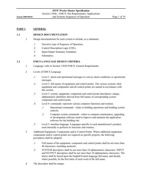
DTW Works Master SpecificationSection 13846 <strong>EMCS</strong>: <strong>Site</strong> <strong>Requirements</strong>, <strong>Applications</strong>Issued 2005/06/01 <strong>and</strong> <strong>Systems</strong> <strong>Sequences</strong> <strong>of</strong> Operation Page 1 <strong>of</strong> 19PART 1GENERAL1.1 DESIGN DOCUMENTATION.1 Design documentation for each system to include, as a minimum:.1 Narrative type <strong>of</strong> Sequence <strong>of</strong> Operation..2 Control Description Logic (CDL)..3 Input/Output Summary Schedules..4 Schematics.1.2 <strong>EMCS</strong> LANGUAGE DESIGN CRITERIA.1 Language: refer to Section 13830 <strong>EMCS</strong>: General <strong>Requirements</strong>..2 Levels <strong>of</strong> <strong>EMCS</strong> Language.1 Level 1: alarm <strong>and</strong> operational messages to convey alarm conditions or operationalmessages..2 Level 2: full names <strong>of</strong> equipment <strong>and</strong> control points. The various systems, theirequipment <strong>and</strong> components <strong>and</strong> all control points are named in accordance withthis section..3 Level 3: system, equipment, component <strong>and</strong> control point descriptors: unique,alphanumeric identifiers derived from full names <strong>of</strong> corresponding systemcomponent <strong>and</strong> control point..4 Level 4: comm<strong>and</strong>s: represent various computer functions <strong>and</strong> routines..1 Operational comm<strong>and</strong>s relate to building operations <strong>and</strong> building systemcontrols..2 Computer system comm<strong>and</strong>s relate to computer maintenance, upgradingor development s<strong>of</strong>tware used to improve <strong>and</strong> maintain the applications<strong>of</strong>tware for the building site..5 Level 5: machine language. Languages specific to each manufacturer's product,used internally to perform its functions <strong>and</strong> routines..3 Additional Equipment, Components <strong>and</strong>/or Control Points. Where additional equipment,components <strong>and</strong>/or control points are required on specific projects, the followingprocedures shall be adopted:.1 Full names <strong>of</strong> the equipment, component <strong>and</strong> control points shall be not more than40 characters, including numerals..2 SYSTEM descriptors shall be not more than 10 alphanumeric characters. INPUT<strong>and</strong> OUTPUT descriptors shall be not more than 10 alphanumeric characters. Theletters shall be based upon the English/French language full name, <strong>and</strong> should,where possible, be the first letter <strong>of</strong> each word <strong>of</strong> the full name..4 The descriptor shall be unique.
DTW Works Master SpecificationSection 13846 <strong>EMCS</strong>: <strong>Site</strong> <strong>Requirements</strong>, <strong>Applications</strong>Issued 2005/06/01 <strong>and</strong> <strong>Systems</strong> <strong>Sequences</strong> <strong>of</strong> Operation Page 2 <strong>of</strong> 19.5 Descriptors <strong>and</strong> expansions: table lists st<strong>and</strong>ardized system identifiers <strong>and</strong> point identifiers..1 Table:Identifiers <strong>and</strong> ExpansionsEnglish IdentifierEnglish Expansion(10 characters max) (40 characters max)OADOutside air damperOATOutside air temperatureOAHOutside air humidityOAVOutside air volumeRADRATRAHRASPReturn air damperReturn air temperatureReturn air humidityReturn air static pressureMAD ** Mixed air dampers **MATMixed air temperatureMAPSPMixed air plenum static pressure** MAD shall be used for applications where outside air <strong>and</strong> return air dampers arecontrolled from one (1) only output signal.EADPFPDPFALMFFPDFFALMHCVLVHCVLVCHCVLVSBPDHCFACCVLVCCVLVCCCVLVSSVLVSVLVCSVLVSExhaust air damperPrefilter pressure dropPrefilter pressure drop alarmFinal filter pressure dropFinal filter pressure drop alarmHeating coil valveHeating coil valve controlHeating coil valve statusHeating coil face <strong>and</strong> bypass damperHeating coil freeze alarmCooling coil valveCooling coil valve controlCooling coil valve statusSteam valveSteam valve controlSteam valve status
DTW Works Master SpecificationSection 13846 <strong>EMCS</strong>: <strong>Site</strong> <strong>Requirements</strong>, <strong>Applications</strong>Issued 2005/06/01 <strong>and</strong> <strong>Systems</strong> <strong>Sequences</strong> <strong>of</strong> Operation Page 3 <strong>of</strong> 19SF#CSupply fan # controlSF#SSupply fan # statusSF#VSDSupply fan # VSD controlSF#VSDF Supply fan # VSD faultSAVSupply air volumeSAVCSupply air volume controlSATSupply air temperatureSAHSupply air humiditySAVP Supply air velocity pressureSASPSupply air static pressureRF#CRF#SRF#VSDRF#VSDFRAVRAVCRATRAHRAVPRASPEF#CEF#SEXATEXAVChiller #1:CH1FCH1LWTCH1LWPCH1EWTCH1EWPCD1EWTCD1EWPCD1LWTCDLWPCHP1FCHP1DPCHP1SReturn fan #controlReturn fan # statusReturn fan # VSD controlReturn fan # VSD faultReturn air volumeReturn air volume controlReturn air temperatureReturn air humidityReturn air velocity pressureReturn air static pressureExhaust fan # controlExhaust fan s# statusexhaust air temperatureexhaust air volumeflow rateleaving chilled water temperatureLeaving chilled water pressureEntering chilled water temperatureEntering chilled water pressureEntering condenser water temperatureEntering condenser water pressureLeaving condenser water temperatureLeaving condenser water pressureChilled water pump #1 flow rateChilled water pump #1 discharge pressureChilled water pump #1 status
DTW Works Master SpecificationSection 13846 <strong>EMCS</strong>: <strong>Site</strong> <strong>Requirements</strong>, <strong>Applications</strong>Issued 2005/06/01 <strong>and</strong> <strong>Systems</strong> <strong>Sequences</strong> <strong>of</strong> Operation Page 4 <strong>of</strong> 19CP3CCP3FCP3DPCP3SHTALTAHTCLTCHLALLAHLCLLCHWFHWSTHWRTSTPSTFRMTRMHRMSPCirculating pump #3 controlCirculating pump #3 flow rateCirculating pump #3 discharge pressureCirculating pump #3 statusHigh temperature alarmLow temperature alarmHigh temperature cutoutLow temperature cutoutHigh level alarmLow level alarmHigh level cutoutLow level cutoutHeating water flow rateHeating water supply temperatureHeating water return temperatureSteam pressureSteam flow rateRoom temperatureRoom humidityRoom static pressure (add reference point)Examples <strong>of</strong> specific space conditions:RMTNPER 2RMSPSPER I9RMHEINT 9AFSAFMFPSTRTFAFTASpace temperature, North Perimeter, 2 nd floorSpace static pressure, South Perimeter, 19th floorSpace humidity, East Interior, 9th floorAir Flow SwitchAir Flow MonitorFlowPressureSupply temperatureReturn temperatureFire alarmFire trouble alarmCWChilled water systemCDCondenser Water SystemHWH Hot water heating systemRADNRadiation system
DTW Works Master SpecificationSection 13846 <strong>EMCS</strong>: <strong>Site</strong> <strong>Requirements</strong>, <strong>Applications</strong>Issued 2005/06/01 <strong>and</strong> <strong>Systems</strong> <strong>Sequences</strong> <strong>of</strong> Operation Page 5 <strong>of</strong> 19CDRHPSLPSDCWDHWDHWRSANPSTMPSPRDSPRWFSTPVBACondensate return systemSteam High pressure systemSteam Low pressure systemDomestic cold water systemDomestic hot water systemDomestic hot water system RecirculationSanitary sewage pumped systemStorm water pumped systemSprinkler Dry pipe systemSprinkler Wet pipe systemFire st<strong>and</strong>pipe & hose systemVolume Box Control Assembly1.3 I/O SUMMARY SCHEDULES.1 General:.1 The <strong>EMCS</strong> contractor shall provide a complete I/O summary schedule similar tothe one listed below, listing <strong>and</strong> describing all I/O’s in detail. Contractor’sst<strong>and</strong>ard schedule may be used provided all relevant information is provided..2 PCU no: identifies the PCU to which all points in the I/O Summary Schedule arewired..3 Building/Area: unique label given to each building forming part <strong>of</strong> a multibuildingfacility..4 Area/System Label: unique label given to each area <strong>of</strong> the building or to eachsystem..1 Column 1: Point no: I/O Summary Schedule reference number..2 Column 2: Point label: unique label for each point in the system. Pointlabels may be repeated for other buildings or systems..3 Column 3: Description: describes the point label in exp<strong>and</strong>ed terms..4 Column 4: Type: (eg. AI, AO, DI, DO)..5 Column 5: Eng. Units: Describes the engineering units used (eg. for AI,AO: C, kPa, Amp Volt. For DI, DO: OFF, ON)..6 Column 6: Access level: Defines the level <strong>of</strong> access for varyingcomplexity <strong>of</strong> functions. Usually associated with password feature.Usually assigned value between 0 (lowest) <strong>and</strong> 4 (highest)..7 Column 7: Sensor type: describes in 2 or 3words..8 Column 8: Assoc. Point: Identifies/ describes points for purposes <strong>of</strong> alarmsuppression, s<strong>of</strong>tware interlocks..9 Column 9: Type: defines the type <strong>of</strong> alarm (eg. CR = CRITICAL, CA =CAUTIONARY, M = MAINTENANCE).
DTW Works Master SpecificationSection 13846 <strong>EMCS</strong>: <strong>Site</strong> <strong>Requirements</strong>, <strong>Applications</strong>Issued 2005/06/01 <strong>and</strong> <strong>Systems</strong> <strong>Sequences</strong> <strong>of</strong> Operation Page 10 <strong>of</strong> 19.18 Miscellaneous Safeties <strong>and</strong> Alarms:The supply <strong>and</strong> return fans shall stop <strong>and</strong> an alarm signal raised upon thefollowing conditions:.1 Smoke detector senses smoke.2 Temperature low limit sensor detects temperature below 5°C.3 Supply duct static pressure exceeds +1000 Pa..4 Return duct static pressure exceeds –1000 Pa..2 Outside Air Units (Hospitals).1 For AHUs which are 100% fresh air heat recovery units, basic unit control logic isthe same as other units. However, these units shall employ a “cold corner”defrostcontrol on the plate exchanger for freeze protection. A multi blade damper <strong>and</strong>modulating 24 V damper actuator are used to deflect cold air away from the coldcorner based on the cold corner leaving air temperature. These units are alsoequipped with heat exchanger bypass dampers. These dampers to be controlledbased on the heat exchanger leaving air temperature to prevent overrecovery.When the temperature leaving the heat exchanger on the supply air side exceeds itssetpoint (initially set at 13°C), the bypass damper shall be modulated open..2 These systems are interconnected by bypass ducts c/w a normally closed damper.Should one <strong>of</strong> the units be taken out <strong>of</strong> service, the bypass damper shall open toallow the operating unit to h<strong>and</strong>le air from the “<strong>of</strong>f”units duct system. Theairflow monitors <strong>and</strong> motorized dampers in the supply <strong>and</strong> return ducts shall beutilized to proportion the available air..3 Should one <strong>of</strong> the units be taken out <strong>of</strong> service, the corresponding interlockedreturn fan shall be shutdown (<strong>and</strong> visa versa). These units, which are operating inparallel, shall be provided with the necessary logic to ensure that each unit delivers50% <strong>of</strong> the airflow despite minor variations in system pressures at each unit..3 Room Temperature Control.1 Reheat or Radiation Only.1 In rooms served only by duct reheat coils or radiation, a drop in roomtemperature as sensed by the rooms wall mounted temperature controller,causes the radiation or reheat coil valve to modulate/open to maintain thespace temperature setpoint. (Operator adjustable within defined limits.).2 Space temperatures shall be set back during unoccupied periods by the<strong>EMCS</strong> system on a schedule to be approved by the owner. An overrideswitch/pushbutton on the face <strong>of</strong> each room temperature controller shallpermit a timed override <strong>of</strong> the night setback in each room..2 Radiation <strong>and</strong> Reheat.1 In rooms served by both duct reheat coils <strong>and</strong> radiation, a drop in roomtemperature as sensed by the room wall mounted temperature controller,causes the radiation heating valve to open. On a further drop in roomtemperature, the reheat coil valve shall be modulated open to maintain thespace temperature setpoint (operator adjustable within defined limits).
DTW Works Master SpecificationSection 13846 <strong>EMCS</strong>: <strong>Site</strong> <strong>Requirements</strong>, <strong>Applications</strong>Issued 2005/06/01 <strong>and</strong> <strong>Systems</strong> <strong>Sequences</strong> <strong>of</strong> Operation Page 11 <strong>of</strong> 19.2 Space temperatures shall be set back during unoccupied periods by the<strong>EMCS</strong> system on a schedule to be approved by the Owner. An overrideswitch/pushbutton on the face <strong>of</strong> each room temperature controller shallpermit a timed override <strong>of</strong> the night setback in each room..3 VAV Box Control with optional radiation/reheat.1 In rooms served by VAV boxes, the box damper shall be closed if theassociated air h<strong>and</strong>ling unit is <strong>of</strong>f <strong>and</strong> reheat/radiation heater valves shallbe open. Prior to start <strong>of</strong> the system, the VAV box damper shall open toits minimum position..2 On a call for cooling, the VAV box controller shall modulate the damperopen to maintain the space temperature setpoint (Operator adjustablewithin defined limits). On a call for heating, the VAV box controller shallmodulate the damper to its minimum position. On a further call for heat,the controller shall open the room’s radiation heating valve (if applicable)to maintain space temperature setpoint. If the temperature still remainsbelow setpoint, the controller shall modulate the reheat coil valve (ifapplicable) to maintain room temperature setpoint..3 For two position only boxes (occupied/unoccupied), the sequence <strong>of</strong>operation is similar to above. The operating position <strong>of</strong> the box shall becontrolled centrally on a schedule by the <strong>EMCS</strong> system or by a local roomoccupancy switch..4 Space temperatures shall be set back during unoccupied periods by the<strong>EMCS</strong> system on a schedule to be approved by the owner. An overrideswitch/pushbutton on the face <strong>of</strong> each room temperature controller shallpermit a timed override <strong>of</strong> the night setback in each room..4 Penthouse/Electrical Room Heating/Ventilation Control.1 When the room space temperature, as sensed by the wall mountedtemperature controller, exceeds its setpoint <strong>of</strong> 24°C, the outside airdamper shall open. On a further rise in room temperature, the exhaust fanshall start. On a drop in room temperature, the reverse sequence shalloccur..2 When the space temperature drops below the heating setpoint <strong>of</strong> 15°C, theunit heater control valve shall open <strong>and</strong> the unit heater fan shall start..5 Unit Heater/Cabinet Heater Control Sequence.1 On a call for heat as sensed by the room temperature controller, the heatercontrol valve shall open <strong>and</strong> the fan shall start..2 Fan speed shall be manually adjustable from within cabinet enclosure(where applicable)..6 Hot Water Heating Heat Exchanger Control.1 One <strong>of</strong> the hot water heating primary pumps shall run continuously tocirculate hot water through the primary heating loop. The pumps shall bealternated on a timed shared basis <strong>and</strong> the lag pump shall start should thelead pump fail.
DTW Works Master SpecificationSection 13846 <strong>EMCS</strong>: <strong>Site</strong> <strong>Requirements</strong>, <strong>Applications</strong>Issued 2005/06/01 <strong>and</strong> <strong>Systems</strong> <strong>Sequences</strong> <strong>of</strong> Operation Page 12 <strong>of</strong> 19.2 The heat exchanger steam valves shall be modulated as required tomaintain the leaving hot water temperature at its setpoint. The leavingwater temperature setpoint shall be reset based on an outside airtemperature schedule..3 The exchangers must be able to operate in parallel or in isolation shouldone <strong>of</strong> the exchanger circuits be down for maintenance. Normal operationis for one heat exchanger to carry the load..7 Main Secondary Heating Loop Temperature/Pressure Control.1 One <strong>of</strong> the hot water heating secondary pumps shall run continuously tocirculate hot water through the secondary heating loop. The three pumpsshall be alternated on a time shared basis <strong>and</strong> the lag pump shall startshould the lead pump fail..2 One, two or three <strong>of</strong> the secondary pumps shall be run at a time asrequired to maintain the set differential pressure in the secondary loop assensed by the differential pressure sensor. Sensor to be located near thefar end <strong>of</strong> the heating loop..3 The hot water mixing valve shall be modulated as required to maintain thehot water supply temperature at its setpoint. The setpoint <strong>of</strong> the hot watersupply temperature shall be reset based on an outside air temperatureschedule..8 Reheat/Perimeter Heating Loop Temperature Control(Typical for Administration/Support Area, Central Area, Patient Area).1 One <strong>of</strong> the two dedicated hot water heating pumps shall run continuouslyto circulate hot water through the heating loop. The pumps shall bealternated on a time shared basis <strong>and</strong> the lag pump shall start should thelead pump fail..2 The hot water mixing valve shall be modulated as required to maintain thehot water supply temperature at its setpoint. The setpoint <strong>of</strong> the hot watersupply temperature shall be reset based on an outside air temperatureschedule..9 High Pressure Steam Boilers.1 Each coil tube steam boiler is provided with its own factory installedcontrol panel <strong>and</strong> each boiler can be operated in a st<strong>and</strong> alone mode..2 However, normal operation is for all three boilers to interface with the<strong>EMCS</strong> system for operating setpoints, firing rates <strong>and</strong> lead/lag controlsequencing. Each boiler shall have four points communicating with the<strong>EMCS</strong>, (for pressure, enable, firing rate <strong>and</strong> common alarm)..3 The operators shall be able to change lead boilers, set point <strong>and</strong> sequencepatterns at the local control panel (located near the boilers) or via theoperator workstation..4 The system shall be controlled full modulation 420 mA for the firing rate<strong>and</strong> the logic shall determine the most efficient rate <strong>of</strong> firing prior toselecting the next boiler in sequence.
DTW Works Master SpecificationSection 13846 <strong>EMCS</strong>: <strong>Site</strong> <strong>Requirements</strong>, <strong>Applications</strong>Issued 2005/06/01 <strong>and</strong> <strong>Systems</strong> <strong>Sequences</strong> <strong>of</strong> Operation Page 13 <strong>of</strong> 19.5 On a boiler trip or alarm condition, the lead/lag system shall automaticallystart the next boiler in the sequence <strong>and</strong> alarm the trip condition..6 Status <strong>and</strong> elapsed time shall be provided for call for heat, low fire <strong>and</strong>maximum firing rate..7 The lead/lag system shall incorporate the ability for each boiler to be rununder local (boiler) control panel only for testing purposes..8 The lead/lag system shall reset to commissioned operating conditions inthe event <strong>of</strong> power interruption <strong>and</strong> automatically restart <strong>and</strong> control theboilers to return to normal operation..10 Domestic Hot Water Heat Exchanger Control.1 One <strong>of</strong> the domestic hot water pumps shall run continuously to circulateDHW from the tanks through the heat exchanger <strong>and</strong> back to tanks. Thepumps shall be alternated on a timed schedule <strong>and</strong> the lag pump shall startshould the lead pump fail..2 The heat exchanger steam valves shall be modulated as required tomaintain the leaving water temperature at its setpoint <strong>of</strong> 70°C..3 The exchangers must be able to operate in parallel (normal) or in isolationshould one <strong>of</strong> the exchanger circuits be down for maintenance. Normaloperation is for one <strong>of</strong> the heat exchangers to operate to carry the load..11 Isolation Room Controls.1 A volumetric air control system shall be used to control airflow <strong>of</strong>fset,airflow tracking between supply <strong>and</strong> exhaust air variable volume boxes,provide stable room pressure <strong>and</strong> room environment, monitor room airpressure <strong>and</strong> environmental conditions <strong>and</strong> be capable <strong>of</strong> communicationslink with the <strong>EMCS</strong>..2 Volumetric control shall be capable <strong>of</strong> direct pressure reset applications..3 Isolation room control system to be complete with a <strong>EMCS</strong> basedvolumetric controller, velocity sensors for both supply <strong>and</strong> exhaust airflow, room pressure sensors to monitor pressure between both isolationroom/anteroom <strong>and</strong> anteroom/hospital space, remote alarm panel, filteralarms for HEPA filters, <strong>and</strong> integration with room temperature controlloop..4 Volumetric control shall receive signal from velocity sensors to regulateflow via control regulation <strong>of</strong> variable volume box dampers. Volumetriccontrol to reset airflow differential setpoint through the direct pressurereset control loop..5 Room pressure sensor to be a through the wall device with one endmonitoring the space <strong>and</strong> the other monitoring either the anteroom or theadjacent building corridor. Wall mounted room monitor controller shallreceive differential pressure readings from each room pressure sensor atfrequent intervals <strong>and</strong> display current value on the LCD display..6 Room monitor controller shall be complete with LCD display, key switchcontrol for change in containment state (positive (+), negative (), or
DTW Works Master SpecificationSection 13846 <strong>EMCS</strong>: <strong>Site</strong> <strong>Requirements</strong>, <strong>Applications</strong>Issued 2005/06/01 <strong>and</strong> <strong>Systems</strong> <strong>Sequences</strong> <strong>of</strong> Operation Page 14 <strong>of</strong> 19neutral (no isolation), check <strong>and</strong> reset control, set point adjustment <strong>and</strong>alarm mute. Unit shall be complete with sensor cable..7 Sequence <strong>of</strong> Operation:.1 When room monitor/controller is in the positive (+) roompressurization mode, (Protective Isolation) volumetric controllerto adjust supply <strong>and</strong> exhaust air volume boxes to maintain a 10%higher supply than exhaust airflow differential..2 When room monitor/controller is in the negative () roompressurization mode Infectious Isolation) volumetric controller toadjust supply <strong>and</strong> exhaust air volume boxes to maintain a 10%higher exhaust than supply airflow differential..3 When room monitor/controller is in the neutral (no isolation)mode, volumetric controller to adjust supply <strong>and</strong> exhaust airflowto maintain a 0% airflow differential..4 Filter alarm signal to sound when static differential pressureacross the supply airflow HEPA filter exceeds setpoint (initiallyset at 300 pa)..5 Reheat coil valve to be modulated as required to maintainisolation room space temperature as sensed by room temperaturesensor. Space temperature to be set back to an unoccupiedsetpoint (initially set at 18°C) when the room is not in use..6 Isolation control to signal building automation system when anyalarm condition exists..12 Physiotherapy Area Infloor Radiation Temperature Control.1 The heating water circulation pump shall be comm<strong>and</strong>ed to run when thespace temperature controller calls for heating. Failure <strong>of</strong> the pump shallraise an alarm..2 The three way mixing valve shall modulate to maintain the supply watertemperature to the infloor heating loop at its setpoint (initially set at35°C) as sensed by the water temperature sensor. Should the supplywater temperature ever reach a high limit <strong>of</strong> 50°C, an alarm shall beraised <strong>and</strong> the three way valve shall revert to its normal position(preventing any hot water from entering the infloor loop)..3 The twoway heating valve shall modulate as required to satisfy the spacetemperature setpoint..13 Library/Work Room Infloor Radiation Temperature Control.1 The heating water circulation pump shall be comm<strong>and</strong>ed to run when any<strong>of</strong> the space temperature controllers call for heating. Failure <strong>of</strong> the pumpshall raise an alarm..2 The three way mixing valve shall modulate to maintain the supply watertemperature to the infloor heating loop at its setpoint (initially set at38°C) as sensed by the water temperature sensor. Should the supplywater temperature reach a high limit <strong>of</strong> 50°C, an alarm shall be raised <strong>and</strong>
DTW Works Master SpecificationSection 13846 <strong>EMCS</strong>: <strong>Site</strong> <strong>Requirements</strong>, <strong>Applications</strong>Issued 2005/06/01 <strong>and</strong> <strong>Systems</strong> <strong>Sequences</strong> <strong>of</strong> Operation Page 15 <strong>of</strong> 19the three way valve return to its normal position (preventing any hot waterfrom entering the infloor loop)..3 The modular heating loop valves shall be modulated as required tomaintain the space temperature setpoint as sensed by the roomtemperature controller..14 Miscellaneous Equipment Alarm/Status Points.1 The following equipment shall be monitored by the <strong>EMCS</strong>: (Refer also toI/O list).1 Deaerator control panel (common alarm).2 Surge tank control panel (common alarm).3 Air compressor control panel (common alarm).4 High pressure steam header (pressure status/alarm).5 Low pressure steam header (pressure status/alarm).6 Data room air conditioning unit (common alarm).7 Domestic cold water pressure status..8 Domestic water filters differential pressure..9 Medical Gas Common Alarms.15 Patient Area Infloor Radiant Heating Loop Temperature Control.1 One <strong>of</strong> the two dedicated hot water heating pumps shall run continuouslyto circulate hot water through the heating loop during the heating system.Above a preset outside air temperature (initially set at 20°C), both pumpsshall be <strong>of</strong>f. During operation, both pumps shall be alternated on a runtime shared basis, <strong>and</strong> the lag pump shall start should the lead pump fail..2 The hot water mixing valve shall be modulated as required to maintain thesupply temperature <strong>of</strong> the infloor radiant heating loop at its setpoint(initially set at 35°C)..16 Patient Area Rooms (with inFloor Radiation) Temperature Control.1 The modular heating loop valve serving the room shall be opened on adrop in room temperature as sensed by the room wall mountedtemperature controller. On a further drop in room temperature, the reheatcoil valve shall be modulated open to maintain the space temperature setpoint (operator adjustable within defined limits)..17 Boiler Room Ventilation/Combustion Air.1 This heating <strong>and</strong> ventilation unit provides combustion <strong>and</strong> ventilation airto the boiler room. The units supply fan shall be comm<strong>and</strong>ed to startwhen any one <strong>of</strong> the three boilers are operating or on a call for spacecooling as sensed by the space temperature sensor. The units heating coilpump shall be interlocked to start when the fan starts..2 Prior to start up, the pressure relief dampers in the boiler room shall open.The <strong>EMCS</strong> system shall incorporate logic to modulate the fresh air <strong>and</strong>return dampers as required to satisfy the combustion air requirements with
DTW Works Master SpecificationSection 13846 <strong>EMCS</strong>: <strong>Site</strong> <strong>Requirements</strong>, <strong>Applications</strong>Issued 2005/06/01 <strong>and</strong> <strong>Systems</strong> <strong>Sequences</strong> <strong>of</strong> Operation Page 16 <strong>of</strong> 191, 2 or 3 boilers running or the ventilation/cooling requirements to satisfyspace temperature..3 For temperature control, the <strong>EMCS</strong> controller shall modulate the heatingcoil valve to maintain the supply air temperature setpoint (initially set at15°C). Should the outside air temperature be below 3°C, the heating coilpump shall run (whether the fan is running or not) <strong>and</strong> the heating coilvalve shall go fully open <strong>and</strong> the units face <strong>and</strong> bypass dampers shallmodulate to maintain the supply air temperature setpoint..4 Should the heating coil pump fail, an alarm shall be raised to notify theoperator to manually change over to the spare pump. Should the supplyair temperature drop below 5°C, the unit shall be shut down <strong>and</strong> an alarmraised. A flow switch shall also be installed in the hot water supply line tothe AHU heating coil to monitor flow <strong>and</strong> signal an alarm should a n<strong>of</strong>low or low flow condition exist when ambient air temperatures are belowfreezing..5 Should the H&V unit fail to run or be down for maintenance, the boilerroom relief damper shall open as required to provide cooling (heat relief)or permit combustion air into the room when one or more <strong>of</strong> the boilersare running..6 The units filter bank shall be monitored by the <strong>EMCS</strong> system via adifferential pressure switch. An alarm signal to change the filters shall beraised at a set differential pressure..18 Critical Care Area Environmental Control Sequence.1 Each critical care area room, including OR’s, LDRP’s, Recovery, CCUrooms, Special Procedure, Endoscopy, Nursery, shall be provided withapproved, flush mounted, polished stainless steel monitoring/alarm panelsmounted within the space at a location approved by theEngineer/Architect. Panel shall have concealed continuous hinges <strong>and</strong>keyed cylinder lock. Panels shall display room temperature, humidity <strong>and</strong>pressurization, contain an occupancy override push button, <strong>and</strong>temperature/humidity setpoint switches, <strong>and</strong> abnormaltemperature/humidity, pressurization indicators..2 Occupied Mode:.1 Supply/Return air flow rates, as sensed by the velocity sensors inthe volume control boxes are maintained constant <strong>and</strong> independent<strong>of</strong> duct status pressure fluctuations by a volume regulatingdamper in the volume control boxes..2 A subtract s<strong>of</strong>tware algorithm maintains a constant differencebetween the supply <strong>and</strong> return airflows equal to the difference inthe design airflows shown on the floor plans..3 An alarm shall be raised should flow rates depart from setpoint bymore than 5%. A flashing pilot light on the room panel shall alertroom users to an abnormal airflow condition.
DTW Works Master SpecificationSection 13846 <strong>EMCS</strong>: <strong>Site</strong> <strong>Requirements</strong>, <strong>Applications</strong>Issued 2005/06/01 <strong>and</strong> <strong>Systems</strong> <strong>Sequences</strong> <strong>of</strong> Operation Page 17 <strong>of</strong> 19.4 On a drop in room temperature, the reheat coil valve shallmodulate to maintain the setpoint space temperature as sensed bythe room temperature sensor..5 OR’s <strong>and</strong> LDRP’s to have a “Full Heat”push button in the panelto permit full open operation <strong>of</strong> the heating control valve..6 A room humidity transmitter shall control the output <strong>of</strong> thebooster humidifier serving the space. A duct mounted humiditytransmitter located downstream <strong>of</strong> the booster humidifier shall actas a humidity high limit shut <strong>of</strong>f to close the steam valve shouldthe duct relative humidity reach 80%..7 (In the CCU suite, only one booster humidifier is provided in thecommon duct serving the suite <strong>and</strong> the humidity transmitter shallbe mounted in the common return duct)..8 For rooms provided with HEPA filters on the supply air, adifferential pressure switch shall be used to signal an alarm whenthe HEPA filter pressure drop reaches the change out pressure..3 Unoccupied Mode:.1 Supply airflow shall be reduced to 25% <strong>of</strong> their design valves.“Full Heat”<strong>and</strong> humidifiers shall be deactivated, <strong>and</strong> reheat coilscontrolled as normal to provide space heating. Return airflowsshall be reduced to the supply airflow rate minus the airflow<strong>of</strong>fset. Unoccupied space temperatures shall be 20°C..4 PreOccupancy Mode:.1 At a predetermined time in advance <strong>of</strong> occupancy, airflows shallincrease to their design airflows, humidifiers shall be reactivated,<strong>and</strong> reheat coils shall be controlled to bring the space temperatureto its normal occupied setpoint. “Full Heat”switches shallremain deactivated..19 Gas Scavenging Air Pressure Alarm.1 Each room provided with a gas scavenging exhaust tube shallincorporate a static pressure switch in the general exhaust duct atthe point where the scavenging tube is connected. The switchshall be field set to signal an alarm should the negative pressure inthe duct drops below the set value. The alarm shall be signaledlocally in the room <strong>and</strong> at the main <strong>EMCS</strong> control console..20 . Cafeteria/Servery Air Volume Control.1 The cafeteria/servery area is provided with a constant volume <strong>of</strong> supplyair during the occupied periods. A volume control box is employed on thereturn air duct from the space to control the return air volume. When thekitchen exhaust hood fan is <strong>of</strong>f, all the air is returned via the return airsystem. When the kitchen exhaust hood fan is on, the volume control boxon the return air duct shall reduce the return air flow by the amount <strong>of</strong> airexhausted. This shall maintain the pressure balance in the
DTW Works Master SpecificationSection 13846 <strong>EMCS</strong>: <strong>Site</strong> <strong>Requirements</strong>, <strong>Applications</strong>Issued 2005/06/01 <strong>and</strong> <strong>Systems</strong> <strong>Sequences</strong> <strong>of</strong> Operation Page 18 <strong>of</strong> 19cafeteria/servery area. The volume control box shall be interlocked withthe exhaust hood fan..21 Lab MultiPurpose Room Pressure Control.1 The Lab multipurpose room contains a biosafety cabinet (BSC) that isused intermittently. The BSC recirculates 70% <strong>of</strong> its air through aninternal HEPA filter, but 30% <strong>of</strong> the air is exhausted via ro<strong>of</strong> fan. Thisfan shall be interlocked to run whenever the BSC fan is running. Avolume control box shall be utilized on the return air duct from the roomto reduce the return airflow rate when exhaust fan is on. The return airshall be reduced by an amount equal to the exhaust air rate. This shallmaintain a proper pressure balance for the room. Supply air to the roomshall be maintained at a constant flow rate by a volume control box..22 Chemo Prep/I.V. Additives Room Environmental Control Sequence.1 Chemo Prep Room <strong>and</strong> I.V. Additives Room in the Pharmacy area aretreated as clean rooms <strong>and</strong> must be maintained under positive pressurewhen in use. Each room must be provided with a pressure monitoringstatus <strong>and</strong> alarm panel in the adjacent anteroom..2 Supply <strong>and</strong> return air flow rates, as sensed by the velocity sensers in thevolume control boxes are maintained constant <strong>and</strong> independent <strong>of</strong> ductstatus pressure fluctuations by a volume regulating damper in the volumecontrol boxes..3 A subtract s<strong>of</strong>tware algorithm maintains a constant difference between thesupply <strong>and</strong> return airflows equal to the difference in the design airflowsshown on the floor plans..4 For the Chemo Prep Room, which contains a Bio Safety Cabinet (BSC)which shall be interlocked with its exhaust fan, the volume control boxeson supply <strong>and</strong> return shall modulate to maintain an adequate makeup airsupply to the room while still keeping the room at a slight positivepressure (initially set at 25 pa), as monitored by the static pressuretransmitters..5 An alarm shall be raised should the room’s positive static pressure be lostfor any extended time. Time delays shall be incorporated to preventnuisance alarms due to opening/closing <strong>of</strong> the door. A flashing pilot lighton the room’s alarm panel shall indicate an abnormal airflow/pressurecondition..6 On a drop in room temperature, the reheat coil valve shall modulate tomaintain the set point space temperature as sensed by the roomtemperature sensor..23 Fuel Oil Tank Monitoring/Fuel Metering.1 The fuel oil tank shall be provided with suitable level probes to measureoil <strong>and</strong> water levels..2 The <strong>EMCS</strong> system shall monitor both oil <strong>and</strong> water levels in the tank <strong>and</strong>signal alarms at set high/low oil levels, high water level.
DTW Works Master SpecificationSection 13846 <strong>EMCS</strong>: <strong>Site</strong> <strong>Requirements</strong>, <strong>Applications</strong>Issued 2005/06/01 <strong>and</strong> <strong>Systems</strong> <strong>Sequences</strong> <strong>of</strong> Operation Page 19 <strong>of</strong> 19.3 The <strong>EMCS</strong> system shall incorporate the necessary s<strong>of</strong>tware to monitorfuel consumption based on fuel tank level changes over time <strong>and</strong> providereports <strong>of</strong> fuel consumption over any given time period. Fuelconsumption to be reconciled with fuel deliveries. The <strong>EMCS</strong> shallprovide automatic fuel delivery reports after every fill up..4 The <strong>EMCS</strong> system shall also provide for a local (outside adjacent the oiltank) audible <strong>and</strong> visual alarm <strong>of</strong> high oil levels to help preventoverfilling. Alarm components outside to be housed in NEMA 4Xenclosure..5 The <strong>EMCS</strong> system shall also monitor the vacuum pressure in theinterstitial space on the tank <strong>and</strong> signal an alarm on low vacuum pressure.1.5 INPUT/OUTPUT POINT SUMMARY TABLE.1 The input/output table summarizes the Input/Output (I/O) points for the various systemsas outlined within the <strong>EMCS</strong> specifications <strong>and</strong> control schematic drawings. However, thetables are not all inclusive as they do not list the typical room temperature sensors, reheatcoil valves, radiator valves, unit heater/force flow valves, terminal unit control assemblies,infloor heating manifold loop valves, etc. The number <strong>and</strong> location <strong>of</strong> these devices can befound on the floor plans <strong>and</strong>/or listed in relevant schedules. All points <strong>and</strong> field devicesrequired to accomplish the specified sequence <strong>of</strong> operation shall be provided. Anydiscrepancies in I/O counts between the points list, specs <strong>and</strong> drawings shall be reported tothe Engineer/Architect.1.6 CHILLER INTERFACE.1 The <strong>EMCS</strong> system shall interface with the common chiller management panel suppliedwith the chillers to track all the basic chiller/condenser functions monitored by that panel.The <strong>EMCS</strong> shall be able to map a minimum <strong>of</strong> 32 I/O points per chiller/condenser.Coordinate with the chiller supplier for details <strong>of</strong> points monitored <strong>and</strong> hook uprequirements.PART 2PRODUCTS (NOT APPLICABLE)PART 3EXECUTION (NOT APPLICABLE)END OF SECTION